The original Tektronix Circuit Computer cursor was probably die-cut from a larger sheet carrying pre-printed hairlines:

Machining a punch-and-die setup lies well beyond my capabilities, particularly given the ahem anticipated volume, so milling seems the only practical way to produce a few cursors.
Attaching a cursor blank to a fixture with sticky tape showed that the general idea worked reasonably well:

However, the tape didn’t have quite enough griptivity to hold the edges completely flat against milling forces (a downcut bit might have worked better) and I found myself chasing the cutter with a screwdriver to hold the cursor in place. Worse, the tape’s powerful attraction to swarf made it a single-use item.
Some tinkering showed a single screw in the (pre-drilled) pivot hole, without adhesive underneath, lacked enough oomph to keep the far end of the cursor in place, which meant I had to think about how to hold it down with real clamps.
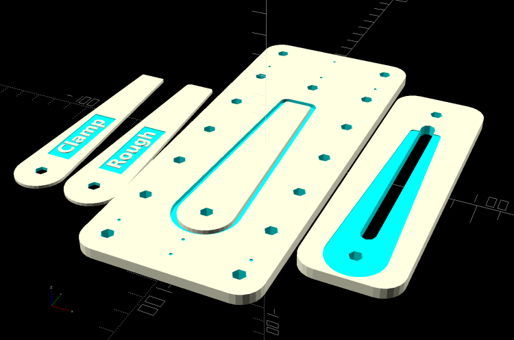
Which, of course, meant conjuring a fixture from the vasty digital deep. The solid model includes the baseplate, two cutting templates, and a clamping fixture for engraving the cursor hairline:

The perimeter of the Clamp template on the far left is 0.5 mm inside the cursor perimeter. Needing only one Clamp, I could trace it on a piece of acrylic, bandsaw it pretty close, introduce it to Mr Belt Sander for final shaping, and finally drill the hole:

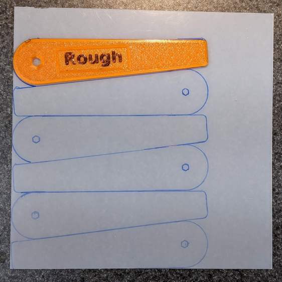
The Rough template is 1.0 mm outside the cursor perimeter, so I can trace those outlines on a PET sheet:

Then cut the patterns with a scissors, stack ’em up, and tape the edges to keep them aligned:

Align the stack by feel, apply the Clamp to hold them in place, and secure the stack with a Sherline clamp:

The alert reader will note it’s no longer possible to machine the entire perimeter in one pass; more on that in a while.
The baseplate pretty much fills the entire Sherline tooling plate. It sports several alignment pips at known offsets from the origin at the center of the pivot hole:

Dropping the laser alignment dot into a convenient pip, then touching off X and Y to the known offset sets the origin without measuring anything. Four screws in the corners align the plate well enough to not worry about angular tweakage.
The OpenSCAD source code as a GitHub Gist:
| // Machining fixtures for Tek Circuit Computer cursor | |
| // Ed Nisley KE4ZNU Jan 2021 | |
| Layout = "Show"; // [Show, Build, Cursor, Clamp, Rough, Engrave] | |
| /* [Hidden] */ | |
| ThreadThick = 0.25; | |
| ThreadWidth = 0.40; | |
| HoleWindage = 0.2; | |
| Protrusion = 0.1; // make holes end cleanly | |
| inch = 25.4; | |
| function IntegerMultiple(Size,Unit) = Unit * ceil(Size / Unit); | |
| module PolyCyl(Dia,Height,ForceSides=0) { // based on nophead's polyholes | |
| Sides = (ForceSides != 0) ? ForceSides : (ceil(Dia) + 2); | |
| FixDia = Dia / cos(180/Sides); | |
| cylinder(d=(FixDia + HoleWindage),h=Height,$fn=Sides); | |
| } | |
| //———————- | |
| // Dimensions | |
| CursorHubOD = 1.0*inch; // original Tek CC was hard inch! | |
| CursorTipWidth = (9.0/16.0)*inch; | |
| CursorTipRadius = (1.0/16.0)*inch; | |
| CursorThick = 0.5; // plastic sheet thickness | |
| CutterOD = 3.175; // milling cutter dia | |
| CutterDepth = 2.0; // … depth of cut | |
| CutterLip = 0.5; // … clearance under edge | |
| ScribeOD = 3.0; // diamond scribe shank | |
| StudOC = [1.16*inch,1.16*inch]; // Sherline tooling plate grid | |
| StudClear = 5.0; // … screw clearance | |
| StudWasher = 11.0; // … washer OD | |
| CursorOffset = [-2*StudOC.x,0,0]; // hub center relative to fixture center | |
| // must have even multiples of stud spacing to put studs along centerlines | |
| BasePlateStuds = [6*StudOC.x,2*StudOC.y]; // fixture screws | |
| echo(str("Stud spacing: ",StudOC)); | |
| CornerRad = 10.0; // corner radius | |
| BasePlate = [2*StudWasher + BasePlateStuds.x,2*StudWasher + BasePlateStuds.y,5.0]; | |
| echo(str("Base Plate: ",BasePlate)); | |
| EngravePlate = [5*StudOC.x,1.5*StudOC.y,BasePlate.z]; | |
| echo(str("Engrave Plate: ",EngravePlate)); | |
| TemplateThick = 6*ThreadThick; | |
| LegendThick = 2*ThreadThick; | |
| Gap = 3.0; | |
| //———————- | |
| // Import SVG of cursor outline | |
| // Requires our hub OD to match reality | |
| // Hub center at origin | |
| module CursorSVG(t=CursorThick,od=0) { | |
| hr = CursorHubOD/2; | |
| translate([-hr,-hr,0]) | |
| linear_extrude(height=t,convexity=3) | |
| offset(r=od/2) | |
| import(file="/mnt/bulkdata/Project Files/Tektronix Circuit Computer/Firmware/TekCC-Cursor-Mark.svg",center=false); | |
| } | |
| //———————- | |
| // Milling fixture for cursor blanks | |
| module Fixture() { | |
| difference() { | |
| hull() // basic plate shape | |
| for (i=[-1,1], j=[-1,1]) | |
| translate([i*(BasePlate.x/2 – CornerRad),j*(BasePlate.y/2 – CornerRad),0]) | |
| cylinder(r=CornerRad,h=BasePlate.z,$fn=24); | |
| translate(CursorOffset + [0,0,BasePlate.z – CutterDepth]) | |
| difference() { | |
| CursorSVG(CutterDepth + Protrusion,1.5*CutterOD); | |
| CursorSVG(CutterDepth + Protrusion,-CutterLip); | |
| } | |
| translate(CursorOffset + [0,0,BasePlate.z – 2*ThreadThick]) { // alignment pips | |
| for (x=[-20.0,130.0], y=[-30.0,0.0,30.0]) | |
| translate([x,y,0]) | |
| cylinder(d=4*ThreadWidth,h=1,$fn=6); | |
| for (x=[-30.0,130.0,150.0]) | |
| translate([x,0,0]) | |
| cylinder(d=4*ThreadWidth,h=1,$fn=6); | |
| } | |
| for (i=[-1,1], j=[-1,1]) // mounting stud holes | |
| translate([i*BasePlateStuds.x/2,j*BasePlateStuds.y/2,-Protrusion]) | |
| rotate(180/6) | |
| PolyCyl(StudClear,BasePlate.z + 2*Protrusion,6); | |
| translate(CursorOffset + [0,0,-Protrusion]) // hub clamp hole | |
| rotate(180/6) | |
| PolyCyl(StudClear,BasePlate.z + 2*Protrusion,6); | |
| translate([2*StudOC.x,0,-Protrusion]) // tip clamp hole | |
| rotate(180/6) | |
| PolyCyl(StudClear,BasePlate.z + 2*Protrusion,6); | |
| for (i=[-2:2], j=[-1,1]) // side clamp holes | |
| translate([i*StudOC.x,j*StudOC.y,-Protrusion]) | |
| rotate(180/6) | |
| PolyCyl(StudClear,BasePlate.z + 2*Protrusion,6); | |
| } | |
| } | |
| //———————- | |
| // Show-n-Tell cursor | |
| module Cursor() { | |
| difference() { | |
| CursorSVG(CursorThick,0.0); | |
| translate([0,0,-Protrusion]) | |
| rotate(180/6) | |
| PolyCyl(StudClear,TemplateThick + 2*Protrusion,6); | |
| } | |
| } | |
| //———————- | |
| // Template for rough-cutting blanks | |
| module Rough() { | |
| bb = [40,12,LegendThick]; | |
| difference() { | |
| CursorSVG(TemplateThick,1.0); | |
| translate([0,0,-Protrusion]) | |
| rotate(180/6) | |
| PolyCyl(StudClear,TemplateThick + 2*Protrusion,6); | |
| difference() { | |
| translate([bb.x/2 + CursorHubOD/2,0,TemplateThick – bb.z/2 + Protrusion]) | |
| cube(bb + [0,0,Protrusion],center=true); | |
| translate([bb.x/2 + CursorHubOD/2,0,TemplateThick – bb.z]) | |
| linear_extrude(height=bb.z,convexity=10) | |
| text(text="Rough",size=7,spacing=1.00,font="DejaVu Sans:style:Bold",halign="center",valign="center"); | |
| } | |
| } | |
| } | |
| //———————- | |
| // Template for aluminium clamping plate | |
| module Clamp() { | |
| bb = [40,12,LegendThick]; | |
| difference() { | |
| CursorSVG(TemplateThick,-1.0); | |
| translate([0,0,-Protrusion]) | |
| rotate(180/6) | |
| PolyCyl(StudClear,TemplateThick + 2*Protrusion,6); | |
| difference() { | |
| translate([bb.x/2 + CursorHubOD/2,0,TemplateThick – bb.z/2 + Protrusion]) | |
| cube(bb + [0,0,Protrusion],center=true); | |
| translate([bb.x/2 + CursorHubOD/2,0,TemplateThick – bb.z]) | |
| linear_extrude(height=bb.z,convexity=10) | |
| text(text="Clamp",size=7,spacing=1.00,font="DejaVu Sans:style:Bold",halign="center",valign="center"); | |
| } | |
| } | |
| } | |
| //———————- | |
| // Engraving clamp | |
| module Engrave() { | |
| difference() { | |
| hull() // clamp outline | |
| for (i=[-1,1], j=[-1,1]) | |
| translate([i*(EngravePlate.x/2 – CornerRad),j*(EngravePlate.y/2 – CornerRad),0]) | |
| cylinder(r=CornerRad,h=EngravePlate.z,$fn=24); | |
| translate(CursorOffset + [0,0,-Protrusion]) | |
| CursorSVG(CursorThick + Protrusion,0.5); // pocket for blank cursor | |
| translate(CursorOffset + [0,0,-Protrusion]) | |
| rotate(180/6) | |
| PolyCyl(StudClear,EngravePlate.z + 2*Protrusion,6); | |
| translate([2*StudOC.x,0,-Protrusion]) | |
| rotate(180/6) | |
| PolyCyl(StudClear,EngravePlate.z + 2*Protrusion,6); | |
| hull() { | |
| for (i=[-1,1]) | |
| translate([i*1.5*StudOC.x,0,-Protrusion]) | |
| PolyCyl(2*ScribeOD,EngravePlate.z + 2*Protrusion,8); | |
| } | |
| } | |
| } | |
| //———————- | |
| // Build it | |
| if (Layout == "Cursor") { | |
| Cursor(); | |
| } | |
| if (Layout == "Clamp") { | |
| Clamp(); | |
| } | |
| if (Layout == "Rough") { | |
| Rough(); | |
| } | |
| if (Layout == "Engrave") { | |
| Engrave(); | |
| } | |
| if (Layout == "Show") { | |
| Fixture(); | |
| color("Green",0.3) | |
| translate(CursorOffset + [0,0,BasePlate.z + Protrusion]) | |
| Cursor(); | |
| color("Orange") | |
| translate(CursorOffset + [0,0,BasePlate.z + 10]) | |
| Rough(); | |
| color("Brown") | |
| translate(CursorOffset + [0,0,BasePlate.z + 20]) | |
| Clamp(); | |
| color("Gold") | |
| translate(0*CursorOffset + [0,0,BasePlate.z + 40]) | |
| Engrave(); | |
| } | |
| if (Layout == "Build"){ | |
| rotate(90) { | |
| Fixture(); | |
| translate([0,-((BasePlate.y + EngravePlate.y)/2 + Gap),EngravePlate.z]) | |
| rotate([180,0,0]) | |
| Engrave(); | |
| translate(CursorOffset + [0,(BasePlate.y + CursorHubOD)/2 + Gap,0]) | |
| Rough(); | |
| translate(CursorOffset + [0,(BasePlate.y + 3*CursorHubOD)/2 + 2*Gap,0]) | |
| Clamp(); | |
| } | |
| } | |
The original doodle with some notions and dimensions that didn’t survive contact with reality:

I have no idea why the Sherline tooling plate has a 10-32 screw grid on 1.16 inch = 29.46 mm centers, but there they are.