Ed Nisley's Blog: Shop notes, electronics, firmware, machinery, 3D printing, laser cuttery, and curiosities. Contents: 100% human thinking, 0% AI slop.
For reasons not relevant here, I walked along IBM Rd to the end of Sand Dock Rd and back, passing the switchyard serving the IBM Poughkeepsie site:
Street View – 1 Sand Dock Rd
The overall capacity is surely in the tens of megawatts and there’s an overwhelming hum coming down that driveway:
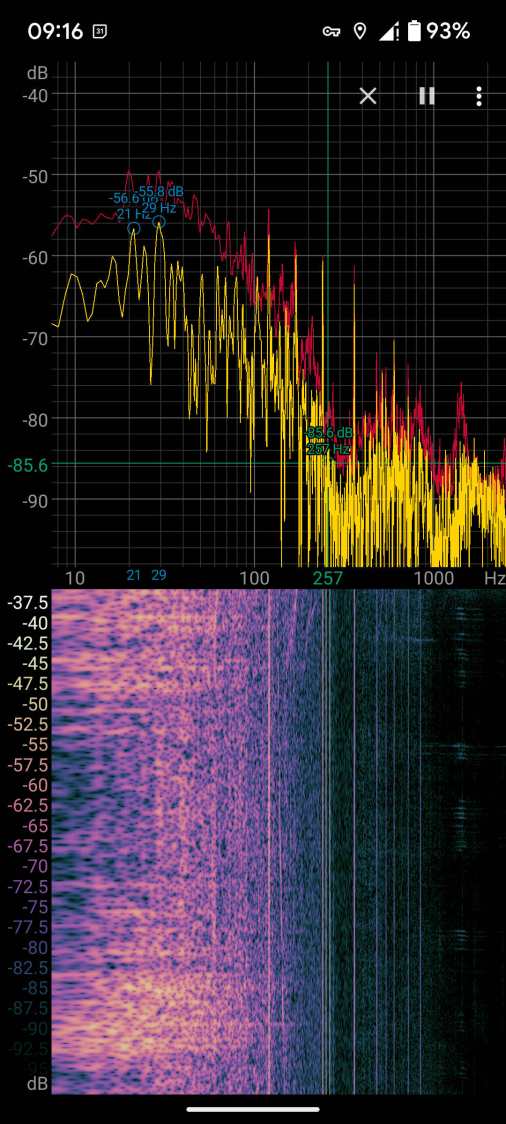
Switchyard hum
Those peaks and the corresponding lines in the waterfall show the equipment emits acoustic energy all the way up to about 480 Hz, call it the eighth harmonic of 60 Hz.
Transformer steel has low magnetostriction, which produces most of the noise at even harmonics of the 60 Hz power line (because each cycle has two current maxima). The spectrogram shows the switchyard handles enough current to emit plenty of odd harmonic energy, with a notable peak at 180 Hz.
For comparison, standing a few feet from the transformer behind a medical office building along IBM Rd:
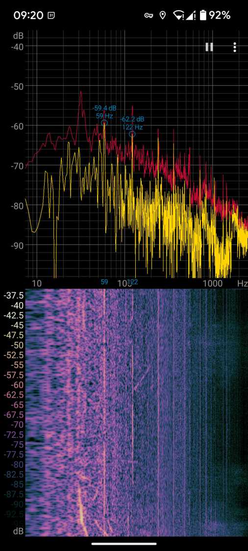
Transformer hum
No 180 Hz energy from that transformer!
Moving a few feet further away dropped those peaks into the background.
Even with my deflicted ears, I think can hear the switchyard hum from a considerable distance along the road, so maybe the background isn’t as quiet as I think.
So these brief notes, compiled before I read the Okendo TOS, should serve the same purpose as an actual review, minus the nonsense of providing even more of my sensitive bits.
Bose discontinued their Hearphones last year. While I’m reasonably happy with how mine work, they seem to last about a year before something fails. Bose replaced the first unit after its covering delaminated, replaced the second unit when a wire failed in the left microphone, and the third unit is now approaching one year of steady use.
The Hearphone necklace curled around the IQbuds charging case:
Bose Hearphones – Nuheara IQbuds2 MAX
Comparing the IQBuds² MAX to the Bose Hearphones:
Heavier in the ears, but without the necklace
Poor battery runtime, both have non-replaceable batteries
Poor ear seal with silicone tips, OK with Nuheara’s foam tips
Immediate access to “World off” mode!
“World off” mode seems noisier, even with ANC on
Better dynamic noise control / filtering
The tradeoff for not having the Bose necklace is, of course, carrying a smaller battery in each ear. Everybody’s claimed run times are optimistic, but after a year the Hearphones still last the better part of a day, while new IQbuds generate range anxiety after a morning and must then spend a while recharging in their case.
The stock IQbud silicone tips exert entirely too much pressure on my ear canals. The foam tips produce a much better seal and were easier to wear for more than a few hours. The Bose “Stayhear” shaped silicone tips fit much better and suppress external sound just as well as the IQbud foam tips.
Replacing the stock IQbuds foam tips (described as “Comply memory foam”) with actual Comply memory foam tips directly from Comply was a definite step up that should not be necessary; they are similar, but visibly different. According to Comply’s online fit selector, you need their Isolation T-167 Sennheiser-specific tips, even though Nuheara hardware appears in Comply’s selector.
The IQbuds tap controls, except for the simplest single tap, barely work. I cannot perform a double-tap, because the bud registers the first tap as a single tap and either discards the second tap or registers it as another single tap. Long taps generally work, except when they don’t, having nothing to do with tap duration or force. Tech support tells me the buds use the audio signal to determine when a finger taps the bud, but AFAICT tap sensitivity is much too high and the discrimination entirely too unfussy.
Amusingly, nibbling dark chocolate can produce exactly the correct audio signal to trigger the “World off” tap in the right bud and, occasionally, the “Play / Pause” tap in the left bud. I rest my case.
For someone requiring far more audio gain than a typical hipster, firmly tapping an ear bud is an … uncomfortable … user interface.
Fortunately, a single correctly executed tap on the right bud mutes the microphones and turns on Active Noise Cancellation; the Hearphones bury that vital function on a tiny icon inside the Bose app, requiring many seconds to start and activate.
The IQbuds app (and, presumably, the bud firmware) does not allow assigning any tap function to any bud + tap pattern. For example, there’s no way to access both “change location” and “change focus” by tapping, because both those functions can be activated only by the right bud’s long tap: you may select one or the other. Weirdly, volume and media controls appear nearly everywhere and, if double taps worked, they’d be useful.
The Hearphones are much better at muting relatively quiet ambient sound, to the extent that I thought the IQbud “World off” function didn’t work. It does, even though it seems tuned to suppress much higher noise levels. Both do a surprisingly good job suppressing loud yard tools, perhaps due to my inability to hear frequencies over a few kHz.
The IQbud noise suppression exhibits horrible gain pumping in noisy environments and windy conditions. It rolls off the overall gain and filters the higher frequencies as the ambient noise increases, then restores them in a rush as the noise subsides: repeating the cycle as the noise level changes. This is very unpleasant and, AFAICT, there is no way to forcibly set a specific gain / bandwidth other than turning the suppression completely off, which misses the point.
Bottom line: I use the IQbuds and they definitely help my hearing, but I don’t particularly like them.
To be fair, I don’t like the Hearphones necklace very much, either, even though, overall, Bose did a better job with the actual earpieces.
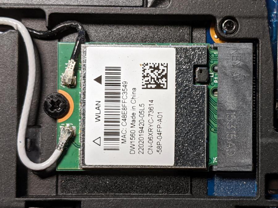
Although the Dell Latitude E7250 allegedly had Bluetooth capability and the Blueman applet tried connecting to my Bluetooth headsets, the connection aways failed and nothing worked. There’s a WLAN module stuck in an M.2 socket inside the laptop providing both WiFi and Bluetooth:
Dell E7250 – DW1560 card in place
A bit of searching suggested the driver wasn’t loading properly, which became obvious after I knew where to look:
dmesg | grep -i blue
… snippage …
[    5.678610] Bluetooth: hci0: BCM20702A1 (001.002.014) build 1572
[    5.678851] bluetooth hci0: Direct firmware load for brcm/BCM20702A1-0a5c-216f.hcd failed with error -2
[    5.678853] Bluetooth: hci0: BCM: Patch brcm/BCM20702A1-0a5c-216f.hcd not found
[   10.854607] Bluetooth: RFCOMM TTY layer initialized
[   10.854613] Bluetooth: RFCOMM socket layer initialized
[   10.854619] Bluetooth: RFCOMM ver 1.11
Without having the proper firmware / patch loaded, the module won’t work, even though the TTY / socket layers know it’s present, which explains why Blueman did everything except actually connect to the headsets.
More searching suggested you must extract the firmware HEX file from the Windows driver. Feeding the Service Tag into the Dell support site, then feeding “Bluetooth” and “Windows 8.1, 64-bit” (preinstalled on the laptop) into the Drivers & Downloads tab gets you the relevant EXE file: Dell Wireless 1550/1560 Wi-Fi and Bluetooth Driver. It turns out to be a self-extracting ZIP file (in Windows, anyway), so unzip it all by yourself:
This produces a blizzard of HEX files in the newly created Drivers/production/Windows8.1-x64 directory. Each firmware HEX file is keyed to the USB Product Code identifying the unique USB gadget, found with lsusb:
lsusb
… snippage …
Bus 002 Device 003: ID 0a5c:216f Broadcom Corp. BCM20702A0 Bluetooth
… snippage …
The DW1560 apparently has a USB RAM interface, with the specific HEX file identified in the CopyList stanza of the INF file corresponding to that USB Product Code:
However, the Linux firmware loader needs a different file format with a different name, mashed together from the HEX file, USB Vendor, and USB Product codes:
The firmware may be in one of the myriad Bluetooth packages not installed by default, so perhaps identifying & installing the proper package would sidestep the hocus-pocus.
Maybe next time?
Now I can wear my Bose Hearphones in Zoom sessions with the E7250, because my Pixel 3a phone heats up almost to the gets-bendy level while thrashing its battery to death.
I got an Alead / Nolan HearLinks (many adjectives) Telecoil receiver to boost my ability to hear music & presentations at Vassar, because they recently slotted telecoil loops into the floors of their public venues. It took a few concerts to get the appropriate volume setting, after which I wondered how sensitive the receiver was:
Alead T-coil receiver – test setup
The small T in the upper right corner marks the receiving coil location, with the coil oriented parallel to the body’s long axis. It’s the secondary winding of an air-core transformer with a single-turn (perhaps using Litz wire) primary embedded in the floor, with the induced voltage obeying the usual transformer equation:
For a given installation and receiver position, pretty much everything is fixed, with the voltage depending only on the H field caused by the primary winding current.
The induced voltage is linearly dependent on the frequency, but the transmitter equalization filters apparently flatten the spectrum to get equal receiver amplitude between about 100 Hz and 5 kHz.
The coil in that picture has nine turns, with four passing through the Tek current probe. Applying 10 mVpp to the winding produces a corresponding current:
JDS6600 10mVpp 1 kHz – 4 turns – 1 mA-div
The scope sees 14 mVpp = 1.4 div at 1 mA/div = 1.4 mA. Dividing by 4 turns means the coil actually carryes 350 µA. The signal generator has a 50 Ω output impedance, so 10 mV should produce about 200 µA, which seems a bit low. On the other paw, the signal generator sees the coil as a dead short at 1 kHz, so I don’t trust the numbers.
Whatever magnetic flux it may be produces a 1 kHz tone at a somewhat higher volume (for the same receiver setting) than the fancy Vassar loops, so the flux is in the right ballpark. With a bit more attention to detail, perhaps I can tinker up a current-mode loop drive amplifier.
The Alead receiver has an internally generated tick audible at the audio volume I need for the Vassar loops, which is 5 to 7 steps down from the maximum volume at 15 steps. It seems related to the internal Bluetooth hardware, although it’s present even when the receiver is not paired with my Pixel phone and, in fact, is unchanged even when 100 feet from the nearest electronic device.
When I reported the problem, they said:
Yes, you can hear very minor tick sound on telecoil mode. It is caused by some electronic and current to make those tick sound. Sorry for this defective on the design.
It had one job that it doesn’t do well, so it’s on the way back for a refund.
Evidently, I must build an audio loop receiver to get what I want …
The volume control wart pod on the cable of my old and longsuffering Lenovo headset had been dropping out the right channel for a while, eventually prompting me to discover it comes apart by simply pulling on the halves:
Lenovo Headset – control pod
There being no way to get closer to the open-frame volume pot’s innards, I eased a drop of DeoxIT Red along its edge (upper in the photo), slipped another drop into what’s presumably the wiper opening in the knob, and ran it through enough cycles to spread the juice evenly.
Reassemble in reverse order and It Just Works™ again.
Our first ride with the Baofeng UV-5 radios subjected us to loud pops around each transmission. Back on the bench, this is the signal applied to the earbud during a no-audio simplex kerchunk:
Baofeng – squelch pops
The small noise burst to the right of the center, just before the downward pulse, happens after the carrier drops and before the squelch closes; it’s familiar to all HT users.
The huge pulses, upward at the start and downward at the end, cause the pops. They’re nearly 3 V tall, compared with the 300-ish mV squelch noise, and absolutely deafening through an earbud jammed in my ear. Mary refused to listen, so we finished the first ride in companionable silence.
I think the radio switches the audio amp power supply on and off to reduce battery drain. It’s obviously a single-supply design, so we’re looking at a hefty DC blocking capacitor charging and discharging through the earbud resistance. I suppose that’s to be expected in a $25 radio.
The obvious solution: clamp the audio signal to something reasonable, perhaps with a pair of nose-to-tail Schottky diodes across the earbud. Rather than using axial diodes, along the lines of the 1N5819 diodes in the WWVB preamp, I used a BAT54S dual SMD diode as a tiny clamp:
BAT54S dual-Shottky diode – SMD package
No pix of the final result, but it’s basically two wires soldered alongside the SMD package, surrounded by a snippet of heatstink tubing to stabilize the wires and protect the SMD leads. It might actually survive for a while, even without the obligatory epoxy blob.
The BAT54S clamps the pops to 200-ish mV, as you’d expect:
Baofeng – squelch pops – clamped – 500mV-div
That’s a kerchunk at twice the vertical scale. The very thin spike at the start of each pop isn’t audible, as nearly as we can tell, and I’ve cranked up the audio gain to make the squelch noise more prominent. Your ears will determine your knob setting.
With the audio amp applying 3 V to the diodes at the start of each pop, you’re looking at an absurdly high pulse current. I’m sure the radio exceeds the BAT54 datasheet’s 600 mA surge current limit by a considerable margin, but I’m hoping the short duration compensates for some serious silicon abuse.
Tamping those pops down made the radios listenable.
I’ve often observed that Baofeng radios are the worst HTs you’d be willing to use.
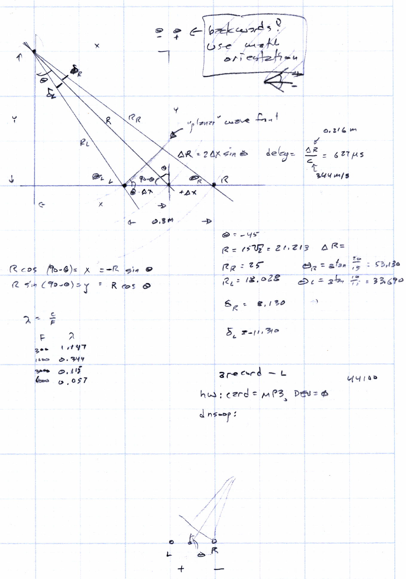
Given a point source of audio (or RF, for that matter) that’s far enough away to produce more-or-less plane wavefronts, the range difference between two microphones (or ears) is:
ΔR = (mic separation) x sin Θ
The angle lies between the perpendicular to the line from the midpoint between the mics counterclockwise to the source source: + for sounds to your left, – for sounds to your right. That’s the trig convention for angular measurement with 0° directly ahead, not the compass convention, but you can argue for either sign if you keep track of what’s going on.
The time delay between the mics, given c = speed of sound:
ΔT = ΔR / c
For microphones 300 mm apart and c = 344 m/s:
ΔT = 872 µs = 0.3 m / 344 m/s
If you delay the sound from the mic closest to the source by that amount, then add the mic signals, you get a monaural result that emphasizes, at least a little bit, sounds from that source in relation to all other sounds.
In principle, you could find the angle by listening for the loudest sound, but that’s a fool’s game.
There’s an obvious symmetry for a source on the same side, at the same angle, toward the rear.
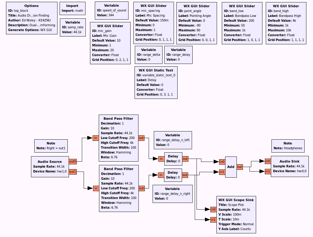
A GNU Radio data flow diagram that lets you set the angle and listen to / watch the results:
Audio Direction Finding.grc
The original doodles show it takes me a while to work around to the answer: