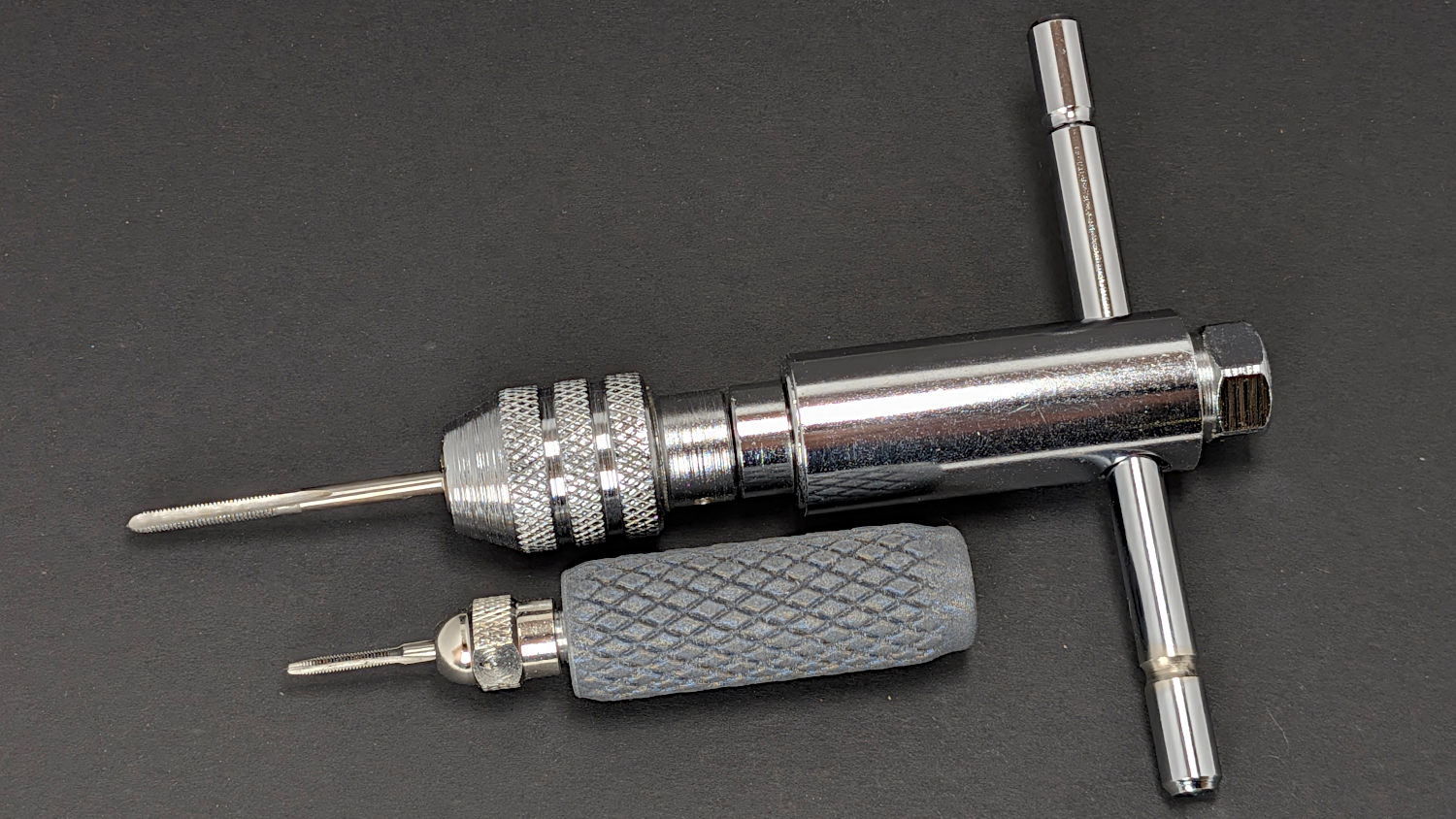
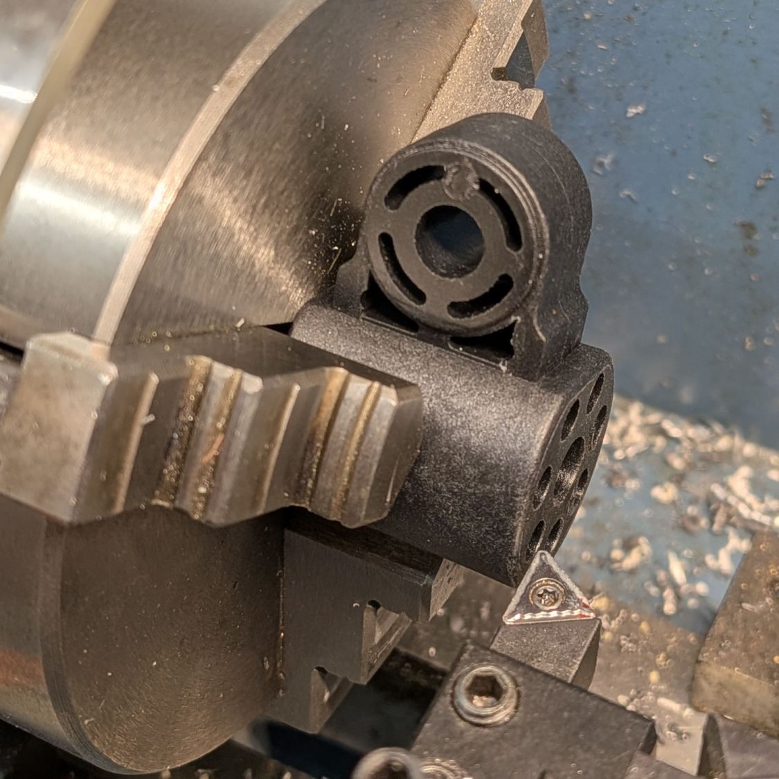
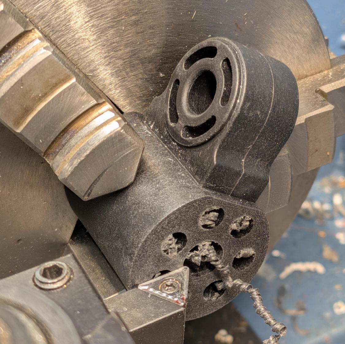
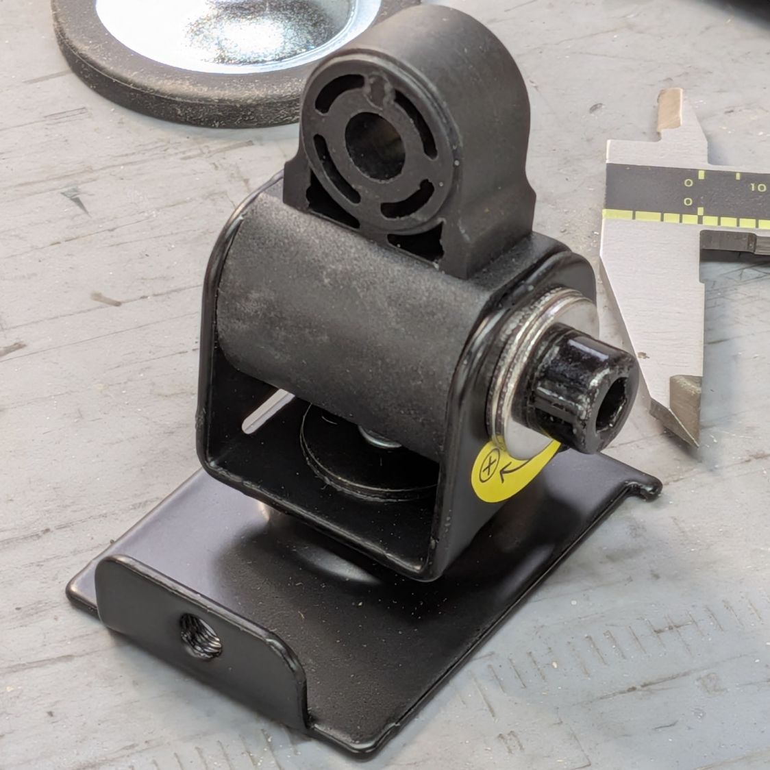
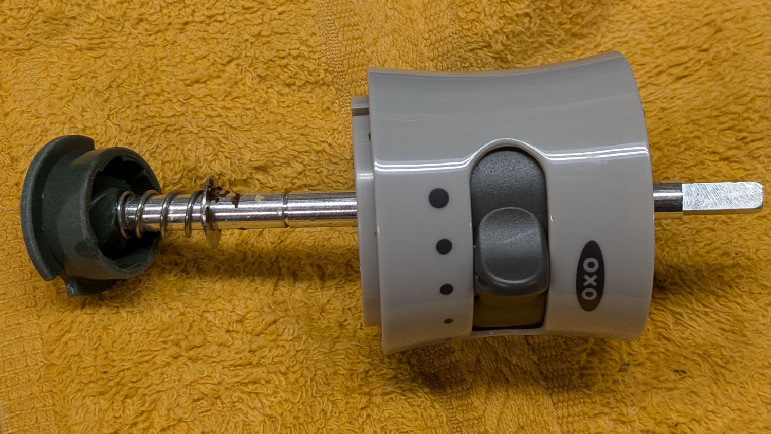
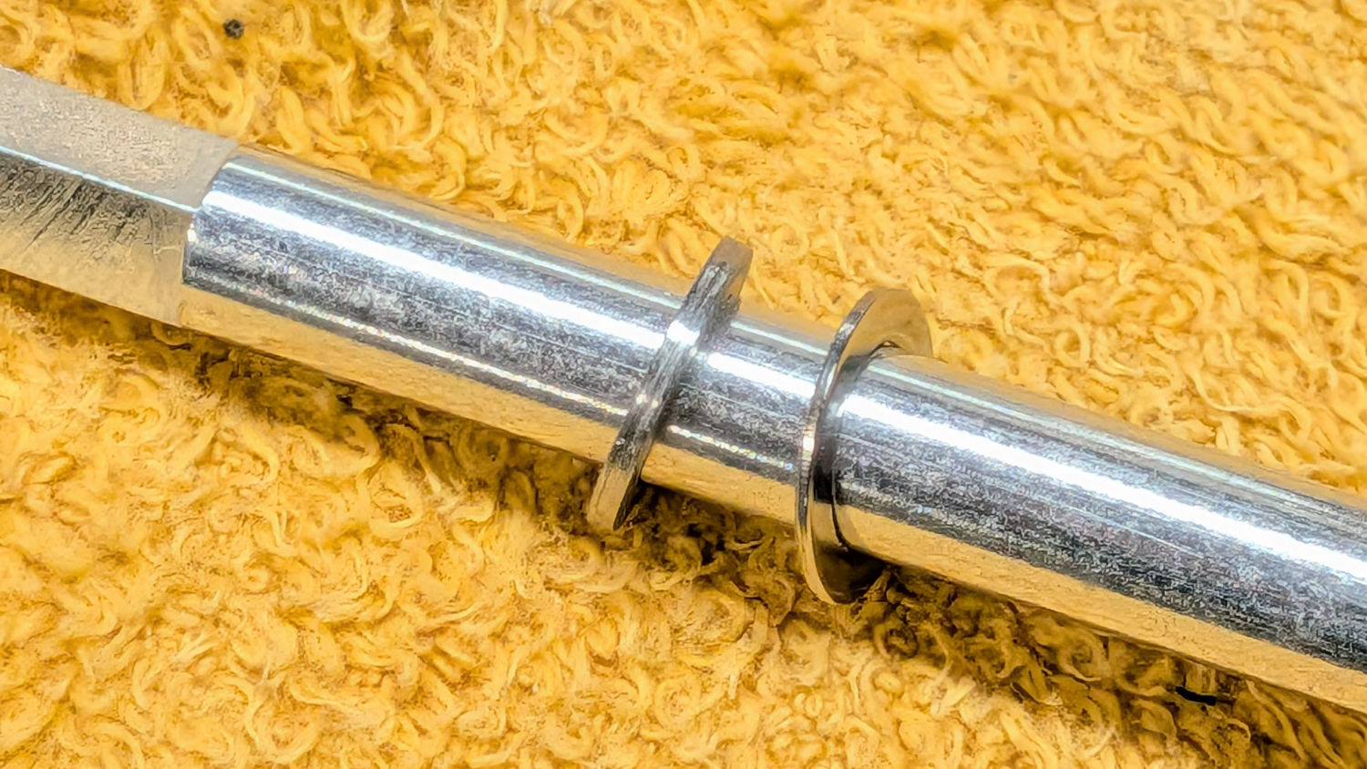
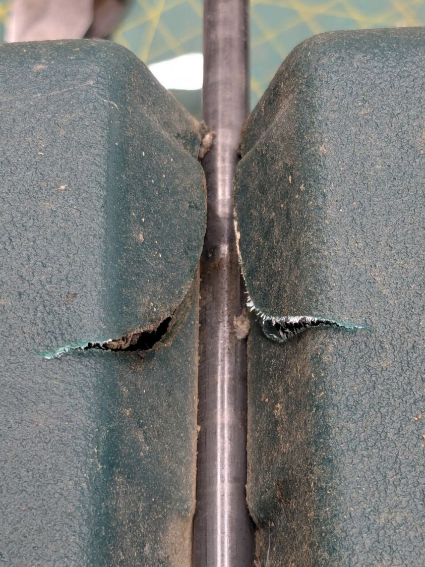
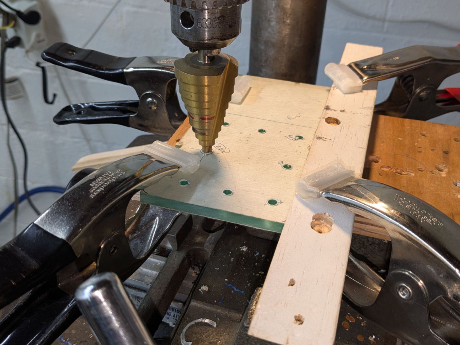
Adapting a previous adapter to put a much longer hose on the Least Shopvac now lurking under the bandsaw / Sherline / lathe workbench:
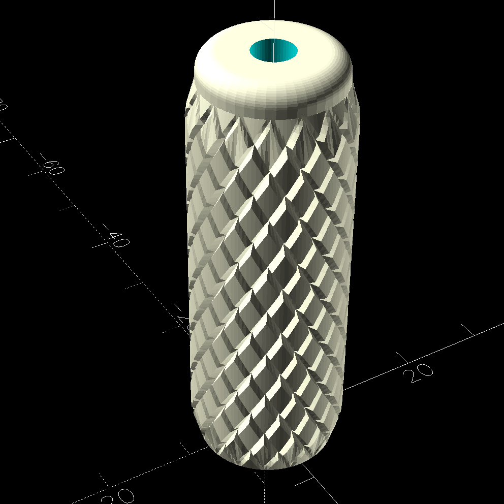
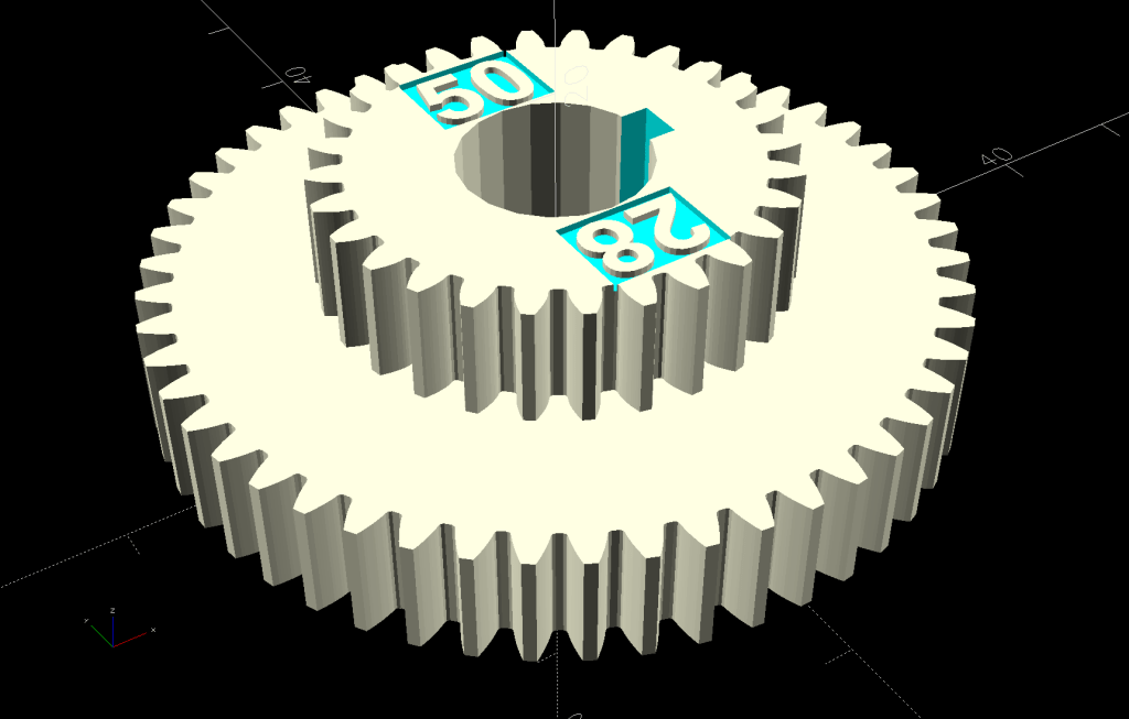
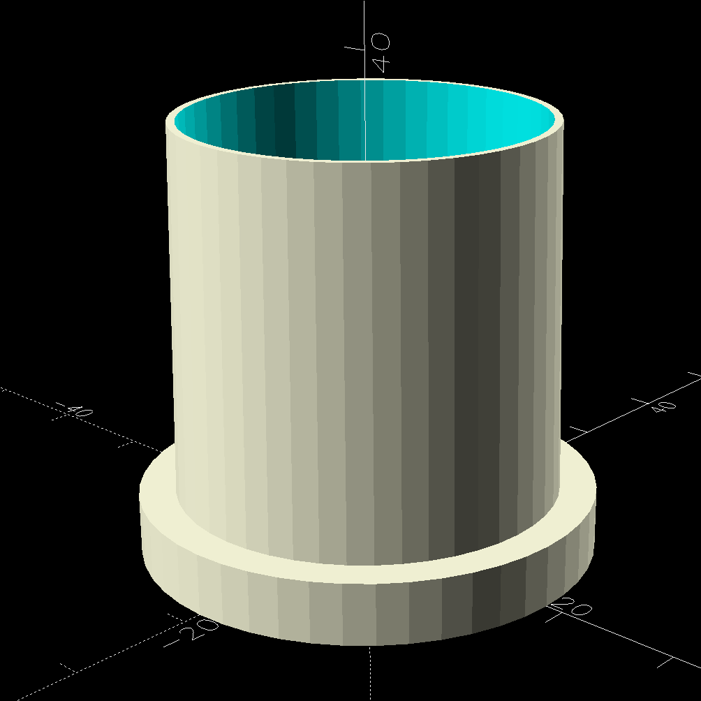
The tapered adapter drags the OpenSCAD code into the BOSL2 era:
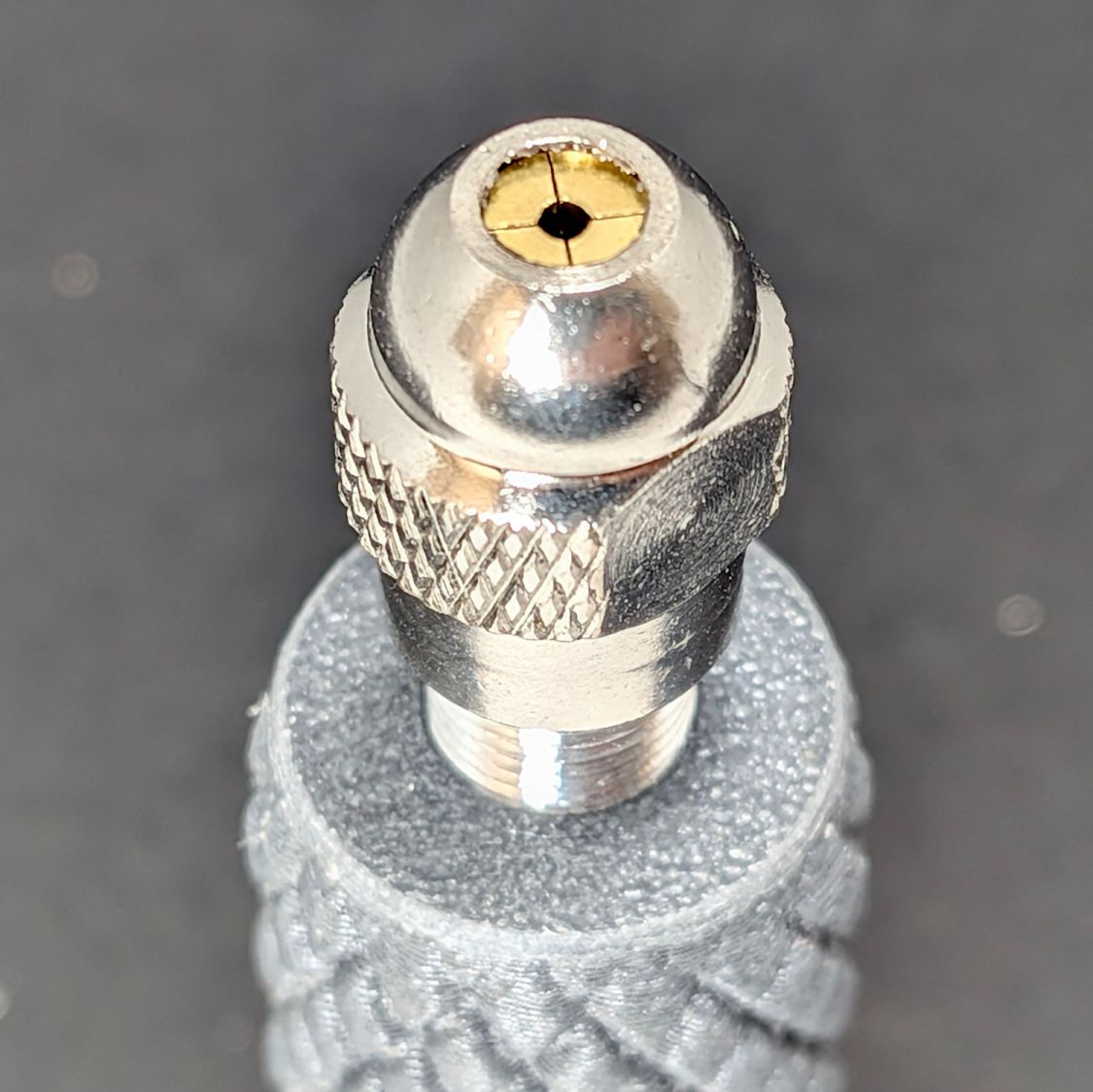
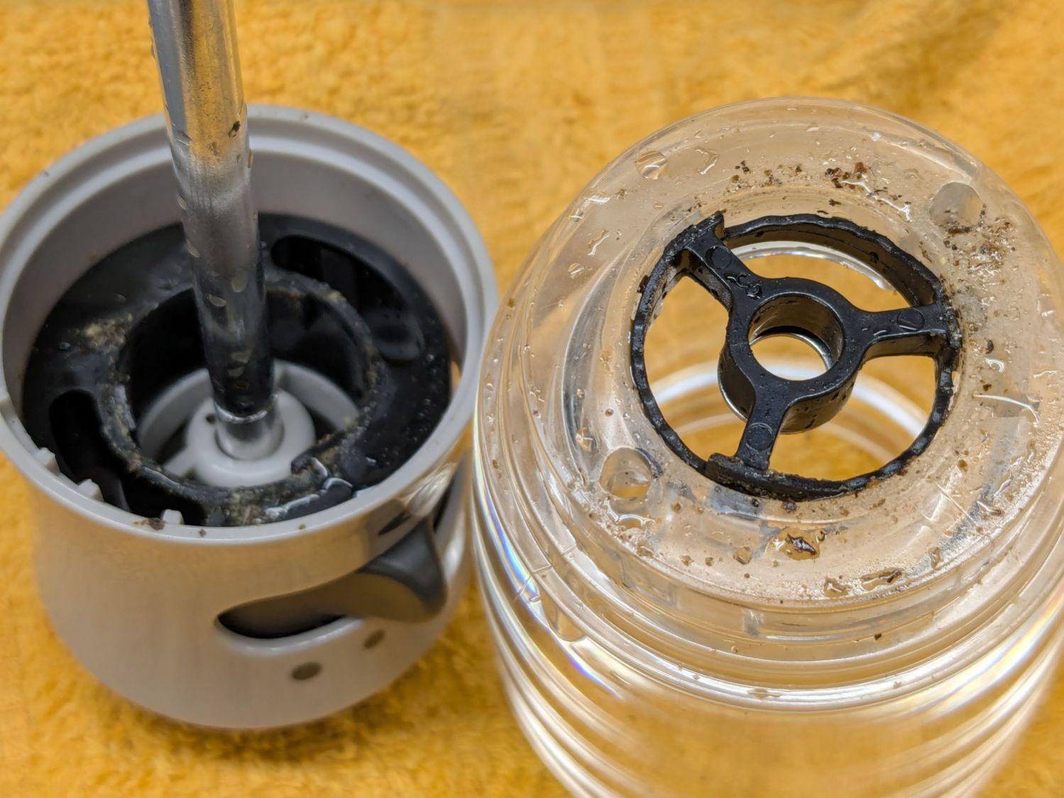
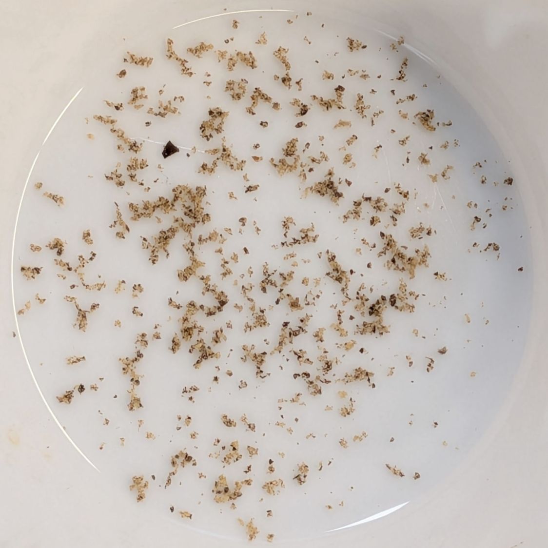
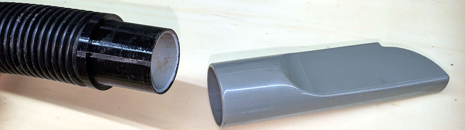
The ID of the hose determined the OD of the lathe-turned PVC tube inside the 3D printed adapter, so a straight pipe would just slide right into both parts.
It would be possible to skip the 3D printing and make the adapter from a single piece of PVC:
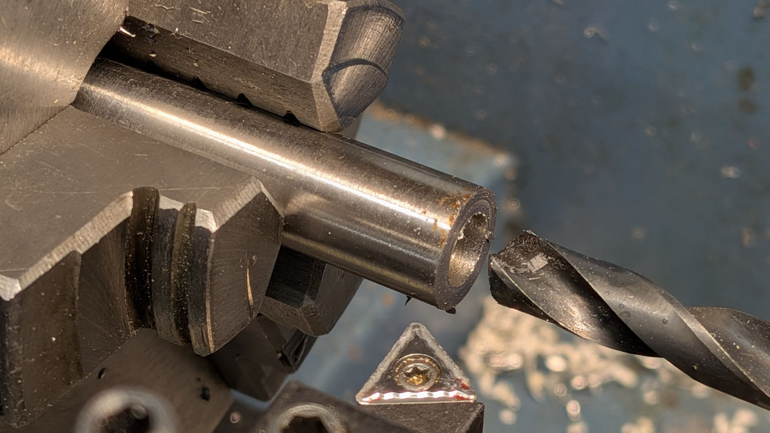
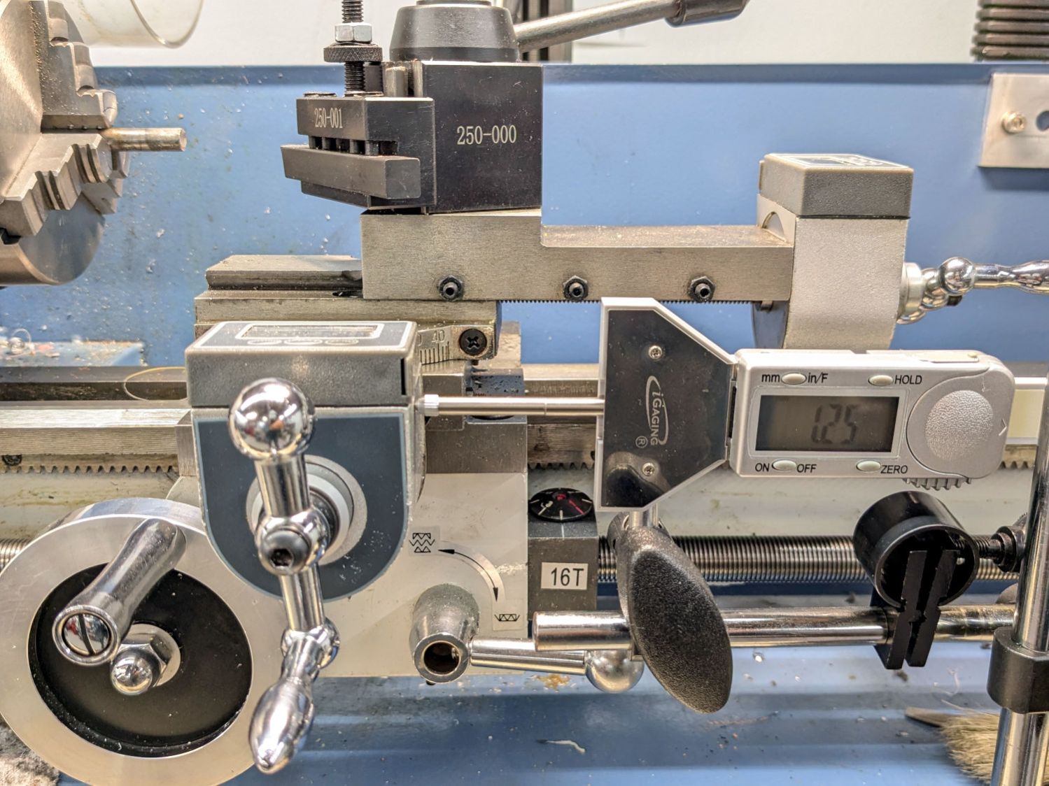
- Turn one end of the conduit to fit the hose ID
- Maneuver the lathe compound to the required 1.05° half-angle
- Turn the taper to fit the crevice tool
- Clean up the original OD between the two sections
Just turning the whole pipe to a smaller OD and sliding the taper on was definitely easier, particularly given the mini-lathe’s cramped quarters with the compound nearly parallel to the bed.
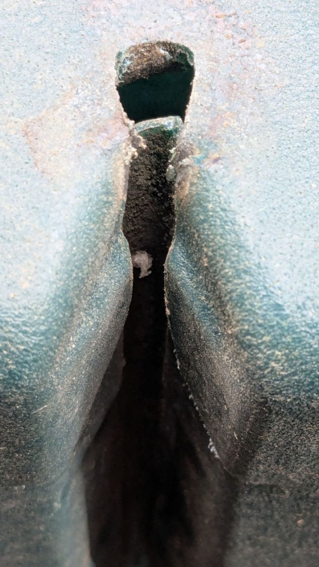
A generous helping of JB PlasticBonder urethane adhesive bonds the PVC pipe inside the vacuum hose and the tapered adapter.
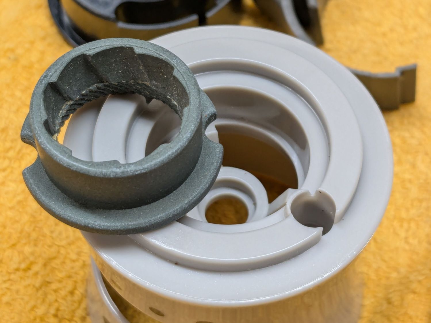
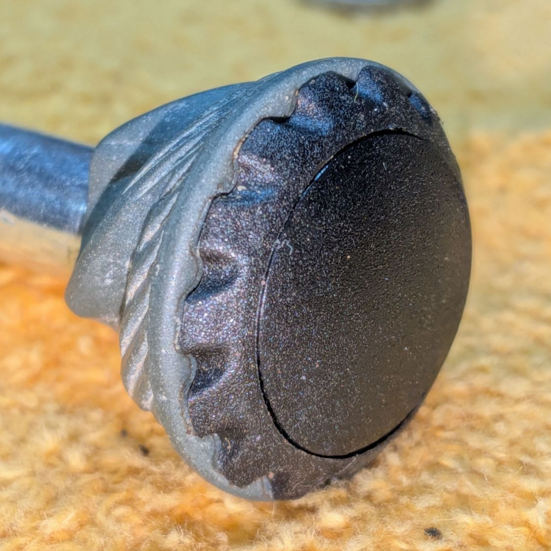
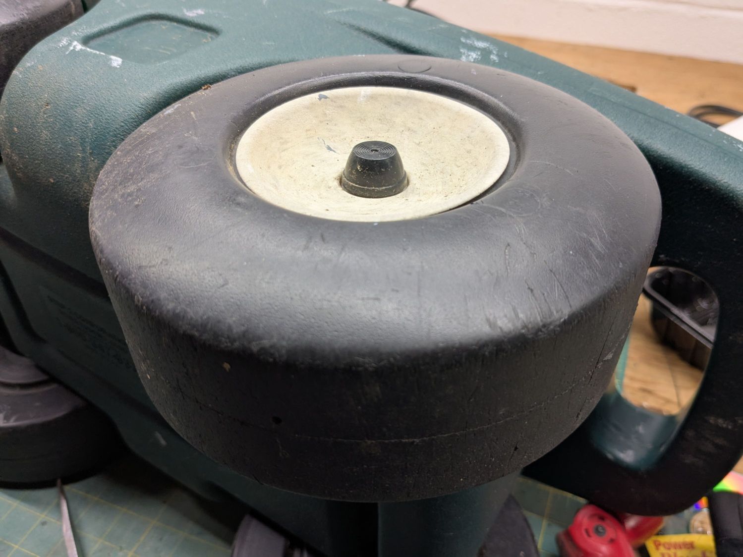
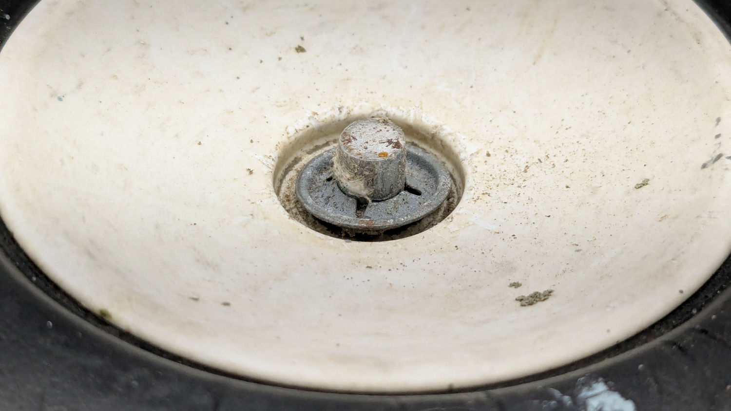
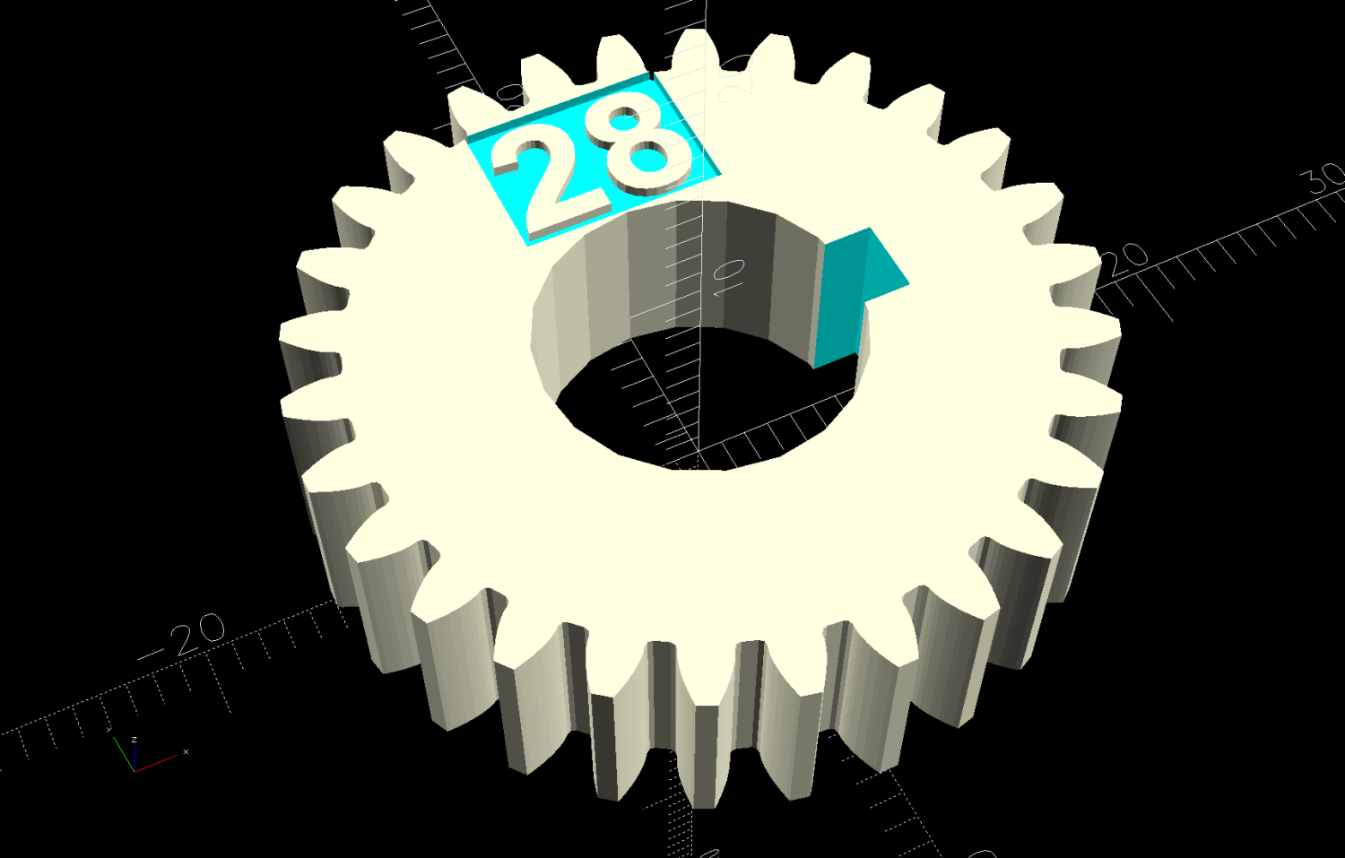
The as-printed taper perfectly fits the crevice tool shown in the picture and is one wrap of electrical tape smaller than another crevice tool of “the same size”. The Finesse variable handles that situation, should it matter to you.
The OpenSCAD source code:
// Shopvac spiral hose to 1.25 in nozzle
// Ed Nisley - KE4ZNU
// 2026-07-25

include <BOSL2/std.scad>

Finesse = 0.2;             // [-0.5:0.1:0.5]

// PVC pipe liner final OD
PipeOD = 28.5;

/* [Hidden] */

NumSides = 4*3*4;
$fn=NumSides;

Protrusion = 0.1;           // make holes end cleanly
HoleWindage = 0.2;          // make holes large enough to fit

//----------------------
// Dimensions

TAPER_MIN = 0;
TAPER_MAX = 1;
TAPER_LENGTH = 2;

Tool = [30.0,31.1,30.0] + [Finesse,Finesse,0];

FlangeOD = 37.0;
FlangeLength = 5.0;

//render()
difference() {

    union() {
        cyl(FlangeLength,d=FlangeOD,anchor=BOTTOM) position(TOP)
          cyl(Tool[TAPER_LENGTH],d1=Tool[TAPER_MAX],d2=Tool[TAPER_MIN],anchor=BOTTOM);
      }

    down(Protrusion)
      cyl(2*Tool[TAPER_LENGTH] + FlangeLength,d=PipeOD + HoleWindage,anchor=BOTTOM);

}