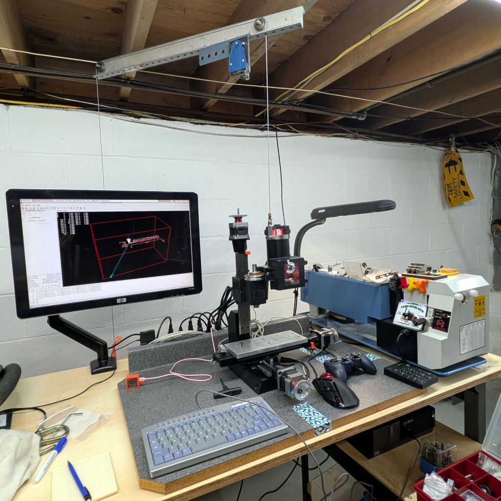
Notes on finally getting the Sherline CNC mill operating in its new home, with a suitable Axis startup image:

The gray countertop from its former home sits on foam strips soaking up a slight warp with enough isolation to keep things quiet.
The gantry required the usual fiddling to make the cable hoist the Z axis directly upward, with the orange flag on the counterweight barely visible below the monitor.
I recently touched the box of precision XYZ positioners and there might be something useful, albeit grossly overqualified, in there to simplify dropping the laser pointer beam directly through the spindle bore.
A clean installation of LinuxCNC 2.9.8 on an ancient Dell Optiplex 9020 proceeded smoothly. Installing x11vnc let the rest of the proceedings happen from upstairs in the Comfy Chair. For unknown reasons, vinagre works better than Reminna as a VNC client, after recalling F11 enters / exits fullscreen mode.
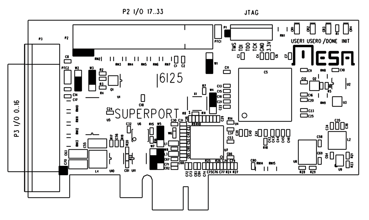
The mesaflash utility accompanying LinuxCNC 2.9.8 did not recognize the Mesa 6i25 card. Fetching & compiling the most recent version (3.5.17) cleared that hump and flashed the bitmap:
sudo mesaflash --verbose --device 5i25 --write 5i25/configs/hostmot2/5i25_prob_rfx2.bit
The 6i25 wants to be known as a 5i25, with its jumpers in their default positions:
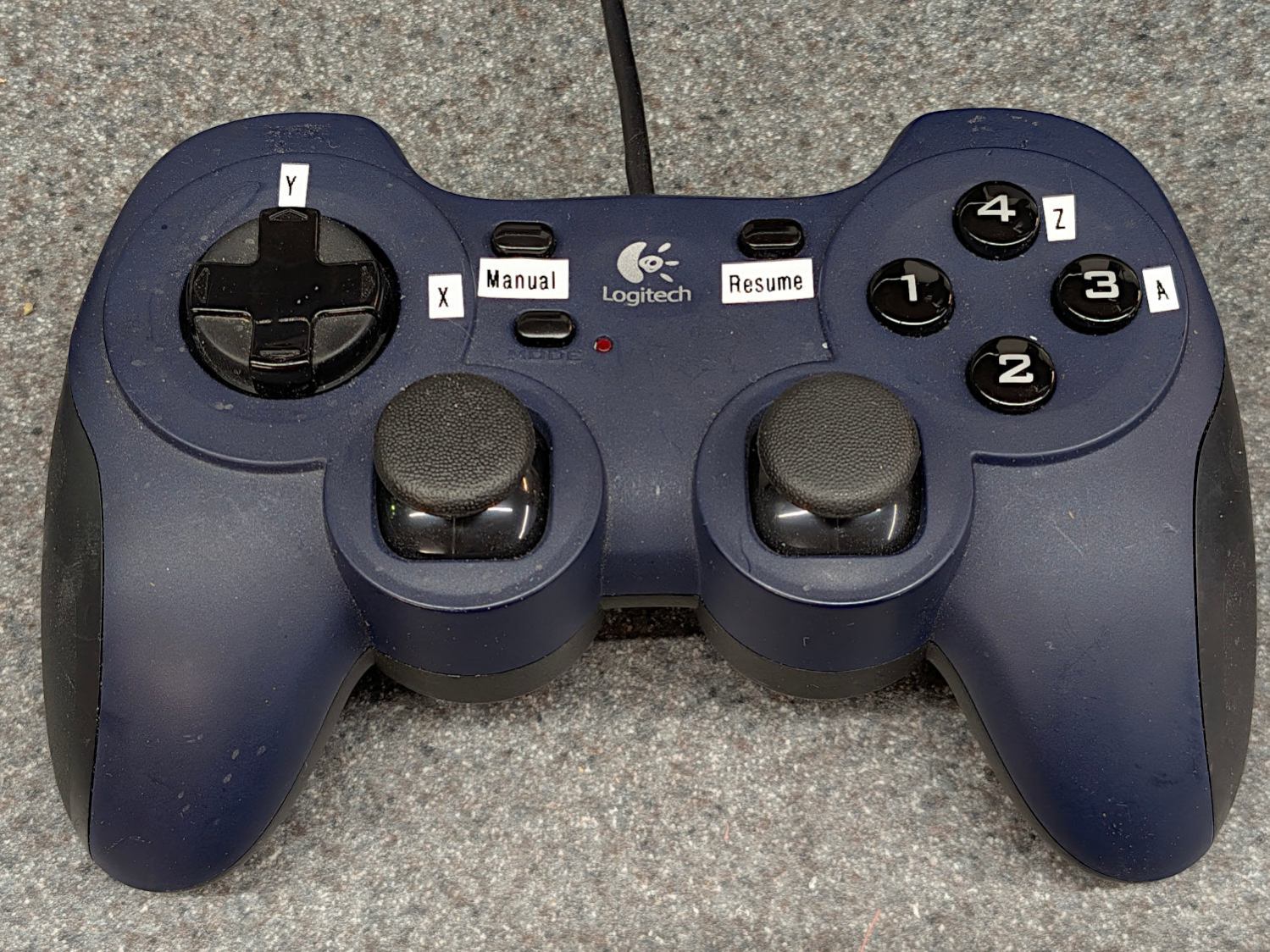
For unknown reasons, the button originally known as btn-trigger became btn-joystick for a while and has now reverted to btn-trigger. It’s labeled 1 in the four-button cluster:
Which required changing the pin name in the Kicad library component:

Which required converting the old Kicad library format into the new Kicad library format, a completely automatic process without, AFAICT, any unpleasant side effects.
The new name fed into the schematic as expected, after minor fumbling while re-adding the modified component and setting its annotation number:

The X axis home microswitch has (apparently) become more bouncy while it was idle, so I increased the number of samples before HAL sees a change in that GPIO input:
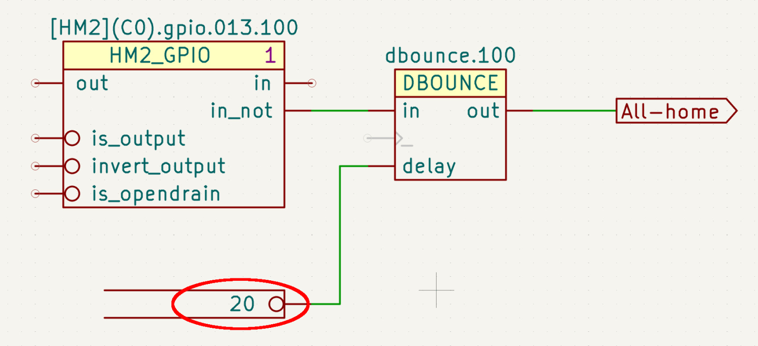
The dbounce block runs in the servo thread at 1 m per tick, so those 20 samples take all of 20 ms while the X axis moves 0.15 mm. At some point I should apply a scope to that switch, but for now It Just Works™.
Considerably to my surprise, compiling the modified Kicad schematic into a HAL file proceeded without incident, despite various Python updates in the last five years.
Kicad produces an “intermediate XML file” containing the netlist data intended for a conversion / export program, which is basically what my Kicad-to-HAL lashup does. I told Kicad to use Bash’s true command as a converter:
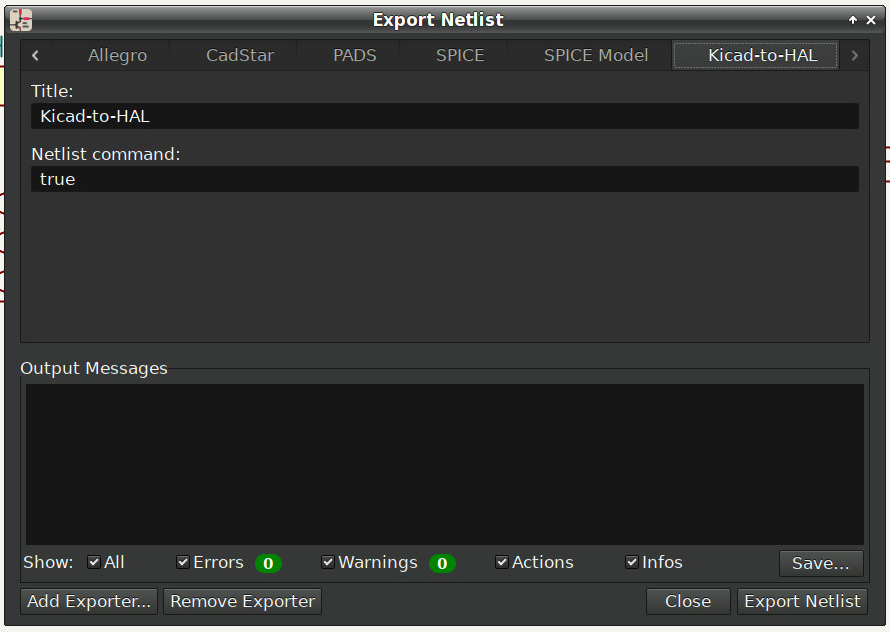
So I can run the Kicad-to-HAL converter manually:
python ../Kicad\ Conversion/Kicad-to-HAL.py Sherline\ HAL\ -\ Logitech\ Gamepad\ jogging.xml Sherline.hal
You could tell Kicad to run it and it would probably Just Work™, but I’m used to peering at the results and dinking with my program.
Which produced a new Sherline.hal file that Just Worked™ with the existing Sherline.ini file containing the configuration constants.
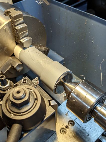
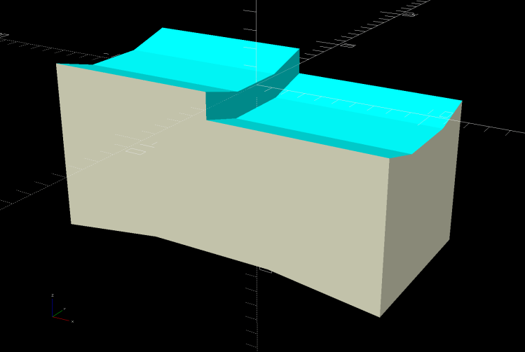
The Sherline has cut only air so far, but, as the man said, “E pur si muove.”