Applying a laser cutter to paper-like materials requires balancing two contradictory imperatives:
- Hold the sheet flat to avoid distortions
- Have nothing below to avoid schmutz on the bottom
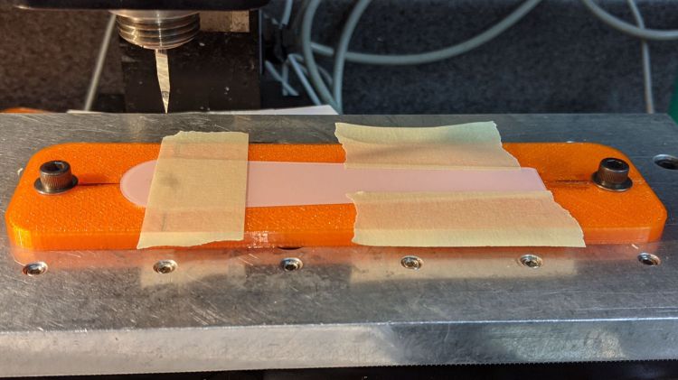
This seemed like a good compromise:
The orange 3D printed blocks hold aluminum miniblind blades:

The curved slots hold the blades flush with the upper surface and align their top sides parallel to the laser beam, giving the beam very little blade to chew on near the focus point and allowing plenty of room below the sheet to dissipate cutting fumes.
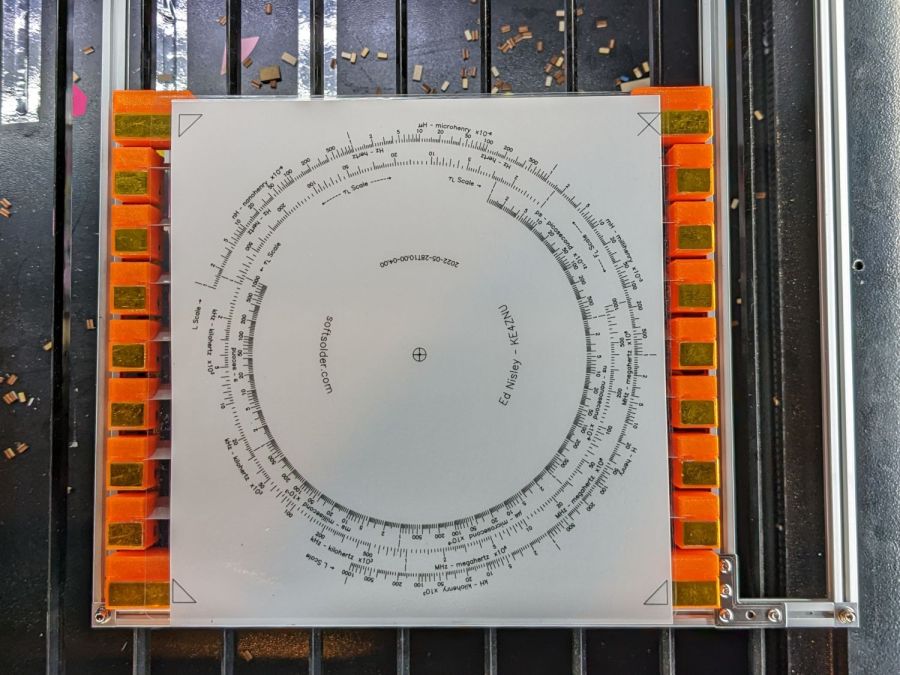
The gold-ish squares are thin steel sheets covered with Kapton tape, painstakingly filed en masse from small snippets:

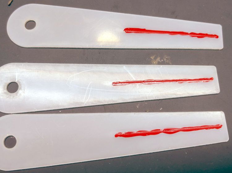
The first iteration used precisely laser-cut refrigerator magnet pieces, in the expectation a crappy rubber magnet would provide just enough attraction to let a neodymium magnets hold the paper flat, without risk of blood blisters between fingers and steel:

As expected, contact with the neo magnet completely wiped away the alternating pole magnetism in the rubber sheet, leaving a weakly attractive non-metallic surface. Alas, the rubber had too little attraction through a laminated sheet of paper, so I switched to real steel and risked the blisters.
Most of the blocks are narrow:
The four corners are wider:

They’re symmetric for simplicity, with recesses for the magnets / steel sheets on the top. The through-holes have recesses for M3 SHCS holding them to T-nuts in Makerbeam rails, with a slightly overhanging alignment ledge keeping them perpendicular to the rail.
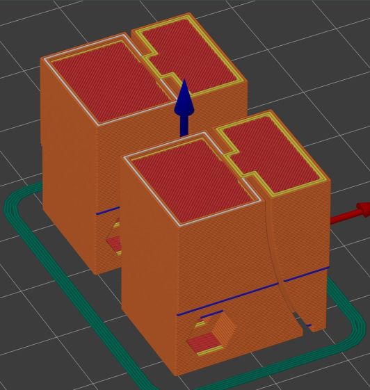
The magnets come from an array of worn-out Philips Sonicare toothbrush heads:
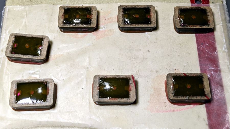
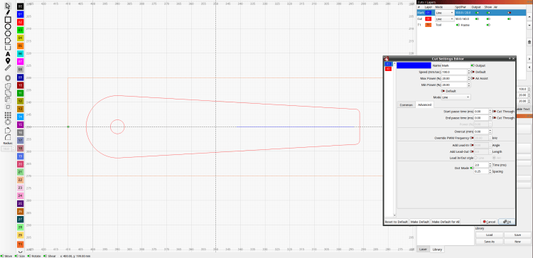
They’re epoxied inside a two-piece mount, with the lower part laser-machined from 3 mm acrylic to put the two magnets in each assembly flush with the lower surface; the green area gets engraved 1 mm below the surface for the steel backing plate. The 1.5 mm upper frame fits around the plate and protrudes over the ends just enough for a fingernail grip:

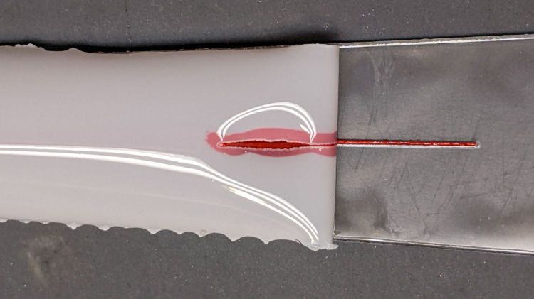
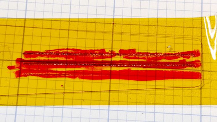
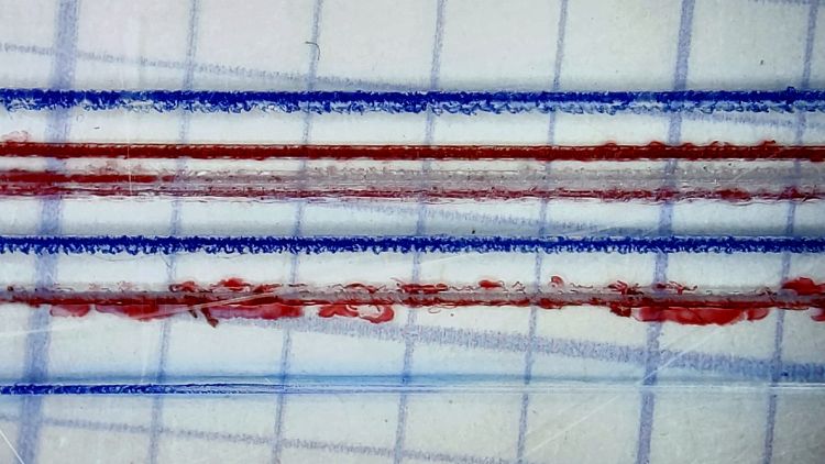
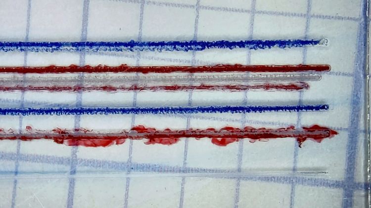
The epoxy got a few drops of fuschia dye, because why not:

The garish trimmings came from slicing the meniscus around the lower part of the holder off while the epoxy was still flexy.
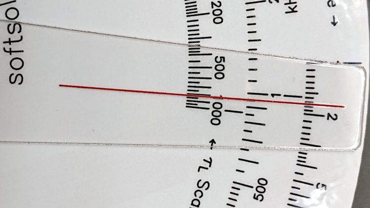
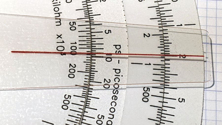
The holders must be flat for clearance under the focus pen:

Some experimentation suggests I can raise the pen by maybe 2 mm (with a corresponding increase in the Home Offset distance) , but the switch travel requires nearly all of the protruding brass-colored tip and there’s not much clearance under the nozzle at the trip point.
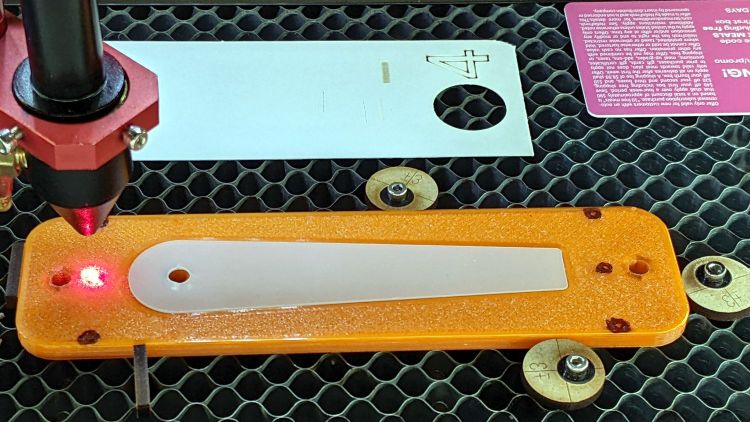
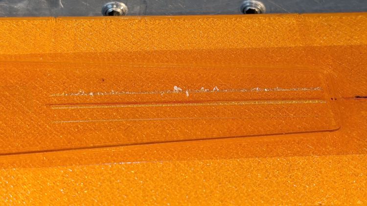
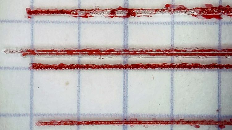
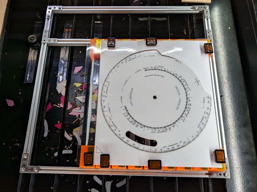
With all that in hand, it works fairly well:

The lower deck has very little margin for gripping, which is why the four corner blocks must be a bit wider than the others.
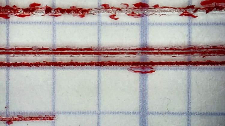
The lamInator tends to curl the sheets around their width, so most of the clamping force should be along the upper and lower edges to remove the curl at the ends. This requires turning the whole affair sideways and deploying more magnets, which is possible for the smaller middle and upper decks:
Protruding SHCS heads on the four corners snug up against the edge of the knife-edge bed opening for Good Enough™ angular alignment.
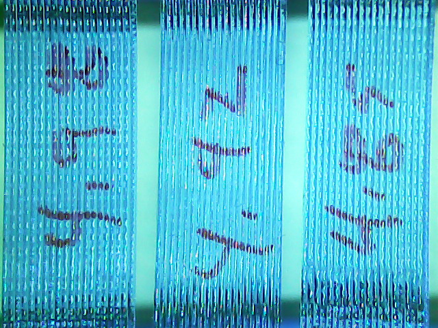
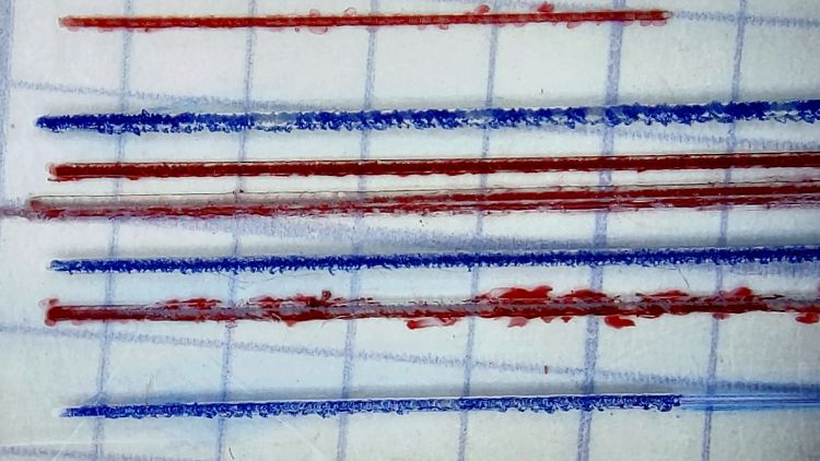
Plain paper (anything non-laminated) seems generally flat enough to require no more than the corner magnets.
It’s definitely better than the honeycomb surface for fume control!
The OpenSCAD source code as a GitHub Gist:
| // Bracket for sheet holder | |
| // Ed Nisley KE4ZNU 2022-09-09 | |
| Layout = "Show"; // [Show, Build, Blade] | |
| /* [Hidden] */ | |
| ThreadThick = 0.25; | |
| ThreadWidth = 0.40; | |
| HoleWindage = 0.2; | |
| Protrusion = 0.1; // make holes end cleanly | |
| ID = 0; | |
| OD = 1; | |
| LENGTH = 2; | |
| module PolyCyl(Dia,Height,ForceSides=0) { // based on nophead's polyholes | |
| Sides = (ForceSides != 0) ? ForceSides : (ceil(Dia) + 2); | |
| FixDia = Dia / cos(180/Sides); | |
| cylinder(r=(FixDia + HoleWindage)/2, | |
| h=Height, | |
| $fn=Sides); | |
| } | |
| // Sizes | |
| Magnet = [10,30,0.5]; // magnetic sheet size | |
| //Magnet = [10,14,0.5]; | |
| MagnetRim = 1.0; | |
| Screw = [3.0,5.5,3.0]; // SHCS OD=head LEN=head | |
| MakerBeam = 10.0; // beam size, screw = half height | |
| BeamRecess = 0.5; // slight overhang for alignment | |
| BladeSlot = 0.15 * 4; // slot with plenty of clearance | |
| BladeSocket = 5.0; // recess to hold miniblind | |
| BladeWidth = 24.6; // miniblind width | |
| BladeM = 1.6; // height of miniblind curve | |
| BladeSides = 12*8; | |
| BladeRadius = (pow(BladeM,2) + pow(BladeWidth,2)/4)/(2*BladeM); | |
| BladeAngle = 2*asin(BladeWidth/(2*BladeRadius)); | |
| echo(BladeRadius = BladeRadius); | |
| echo(BladeAngle = BladeAngle); | |
| Block = [Magnet.x + 2*MagnetRim + ceil(BladeRadius*(1 – cos(BladeAngle)) + 2.0), | |
| Magnet.y + 2*MagnetRim, | |
| BladeRadius*sin(BladeAngle)]; | |
| echo(Block = Block); | |
| // Cutter for spline recess | |
| // approximately correct and good enough | |
| module BladeRing() { | |
| rotate([90,0,0]) | |
| translate([0,0,-BladeSocket]) | |
| linear_extrude(height=2*BladeSocket,convexity=2) | |
| difference() { | |
| circle(r=BladeRadius,$fn=BladeSides); | |
| circle(r=BladeRadius – BladeSlot,$fn=BladeSides); | |
| } | |
| } | |
| // Overall bracket | |
| module Bracket() { | |
| difference() { | |
| translate([0,-Block.y/2,0]) | |
| cube(Block,center=false); | |
| translate([Magnet.x/2 + MagnetRim,0,Block.z – Magnet.z/2 + Protrusion/2]) | |
| cube(Magnet + [0,0,Protrusion],center=true); | |
| for (j=[-1,1]) | |
| translate([0,j*Block.y/2,MakerBeam/2 – Protrusion/2]) | |
| cube([3*Block.x,2*BeamRecess,MakerBeam + Protrusion],center=true); | |
| for (j=[-1,1]) | |
| translate([Magnet.x + 2*MagnetRim + BladeRadius,j*Block.y/2,Block.z]) | |
| BladeRing(); | |
| for (j=[-1,1]) | |
| translate([Block.x – 2.0 – BladeSlot,j*Block.y/2,5*ThreadThick/2 – Protrusion/2]) | |
| cube([2*BladeSlot,2*BladeSocket,5*ThreadThick + Protrusion],center=true); | |
| translate([MakerBeam/2,Block.y,MakerBeam/2]) | |
| rotate([90,0,0]) | |
| PolyCyl(Screw[ID],2*Block.y,6); | |
| for (j=[-1,1]) | |
| translate([MakerBeam/2,j*(Block.y/2 – Screw[LENGTH] – 1.0),MakerBeam/2]) | |
| rotate([-j*90,0,0]) | |
| PolyCyl(Screw[OD] + HoleWindage,2*Block.y,6); | |
| } | |
| } | |
| //———- | |
| // Build it | |
| if (Layout == "Blade") | |
| BladeRing(); | |
| if (Layout == "Show") | |
| Bracket(); | |
| if (Layout == "Build") | |
| Bracket(); |