The Smell of Molten Projects in the Morning

Ed Nisley's Blog: Shop notes, electronics, firmware, machinery, 3D printing, laser cuttery, and curiosities. Contents: 100% human thinking, 0% AI slop.

Category: Recumbent Bicycling

Cruisin’ the streets

  • Tour Easy: E-Bike Brake Sensor Installation

    Tour Easy: E-Bike Brake Sensor Installation

    Having verified the brake sensors work and with some idea of their actuation distances, installing them on Mary’s Tour Easy involved no more than:

    • Remove the fairing
    • Unwrap three spiral looms from All The Cables
    • Wrestle the Julet connectors apart
    • Plug in the new sensors
    • Stick the sensors in the proper locations
    • Verify proper brake operation
    • Rewrap the looms
    • Install the fairing

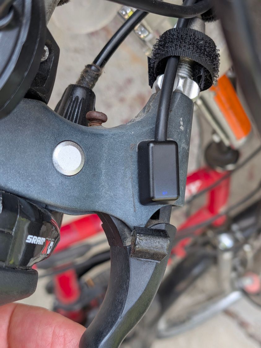
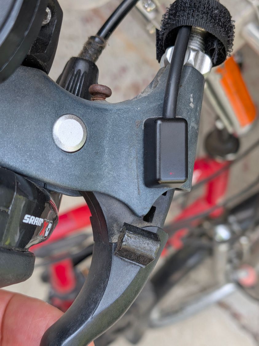
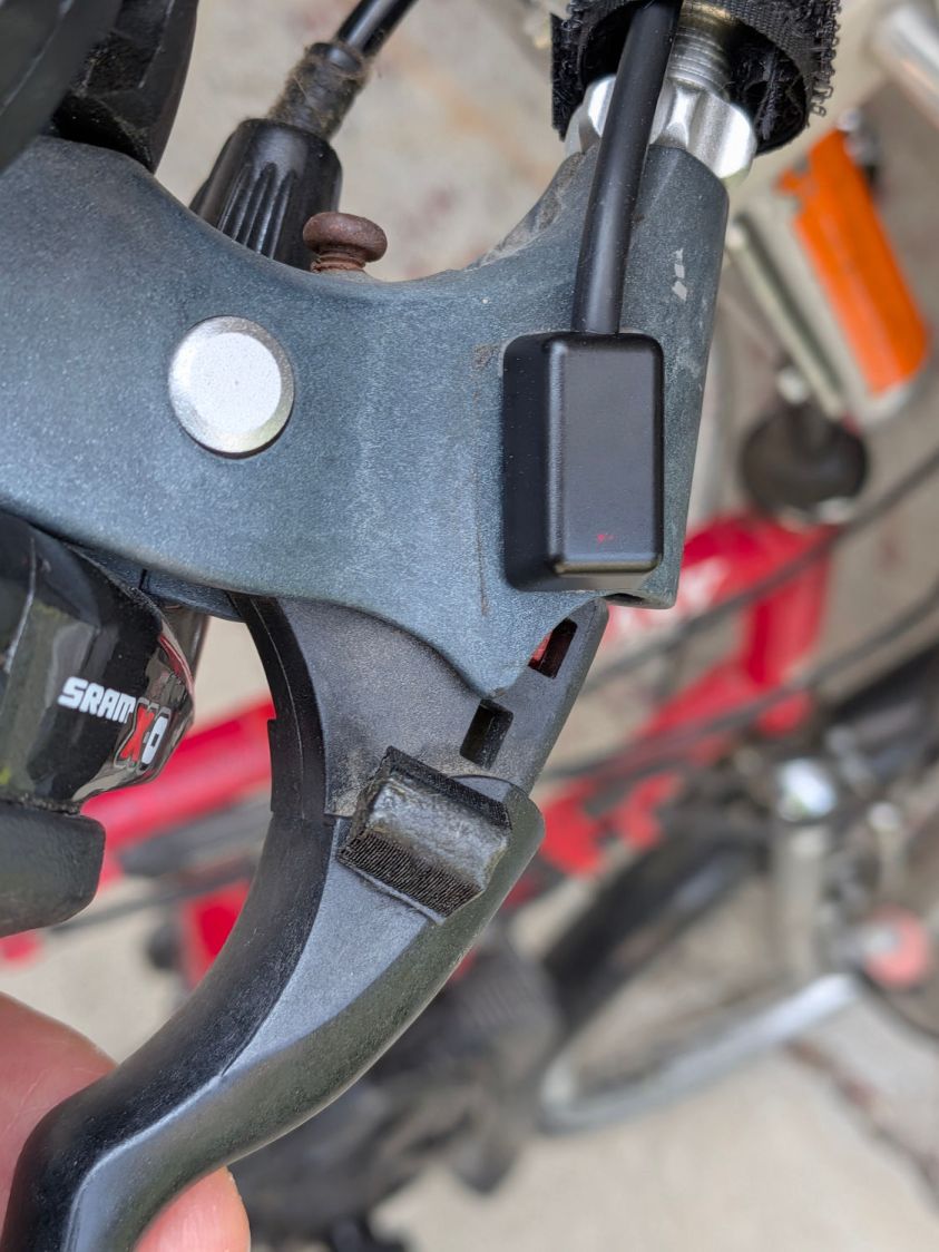
    The “proper location” put the actuation point about halfway between the brake lever’s released and pulled positions. Given that the previous sensors lacked indicators, I don’t know where their actuation point might have been, other than likely too close to their released position.

    A slideshow of the front brake lever positions:

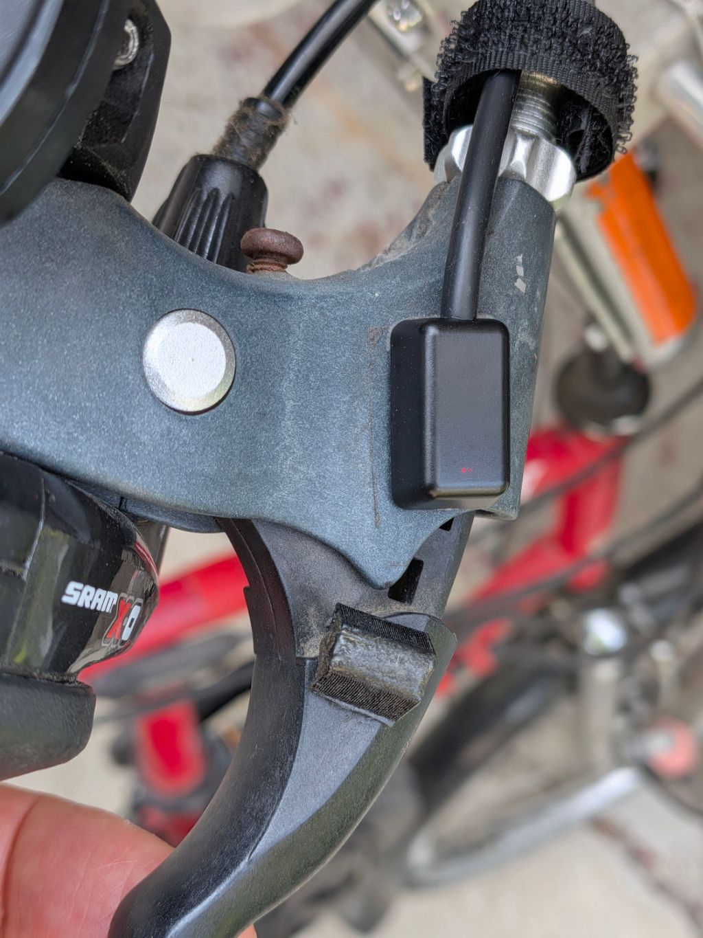
    • Tour Easy LED brake sensor - front released
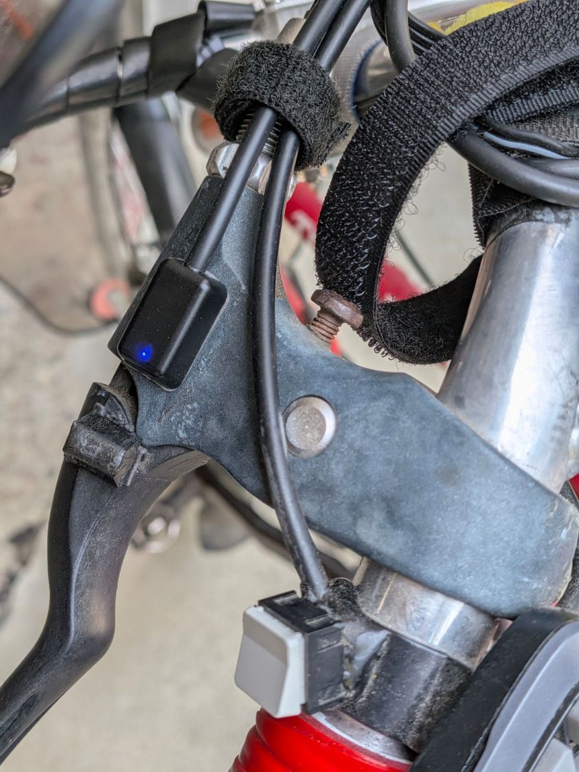
    • Tour Easy LED brake sensor - front activated
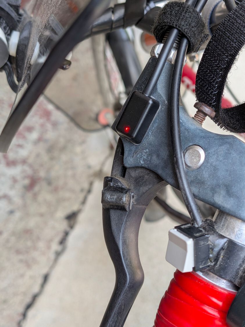
    • Tour Easy LED brake sensor - front pulled

    Similarly for the rear brake lever positions:

    • Tour Easy LED brake sensor - rear released
    • Tour Easy LED brake sensor - rear activated
    • Tour Easy LED brake sensor - rear pulled

    Obviously, the rear brake lever sensor has the “dim” LEDs.

    There’s not much to go wrong and the first ride was uneventful, so we’ll declare victory until the sensors or magnets shift their position, despite the wraps holding their wires to the brake cables.

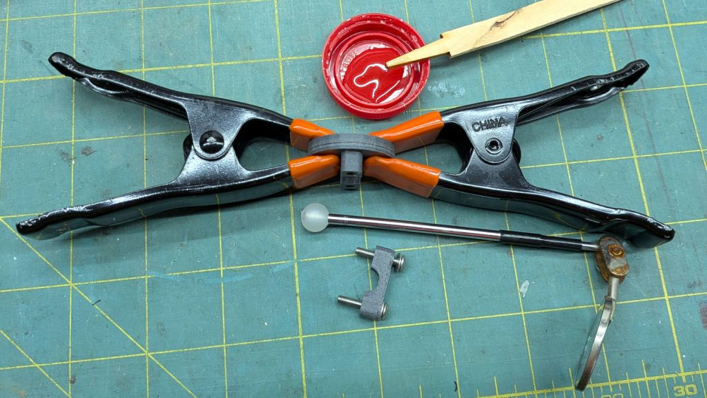
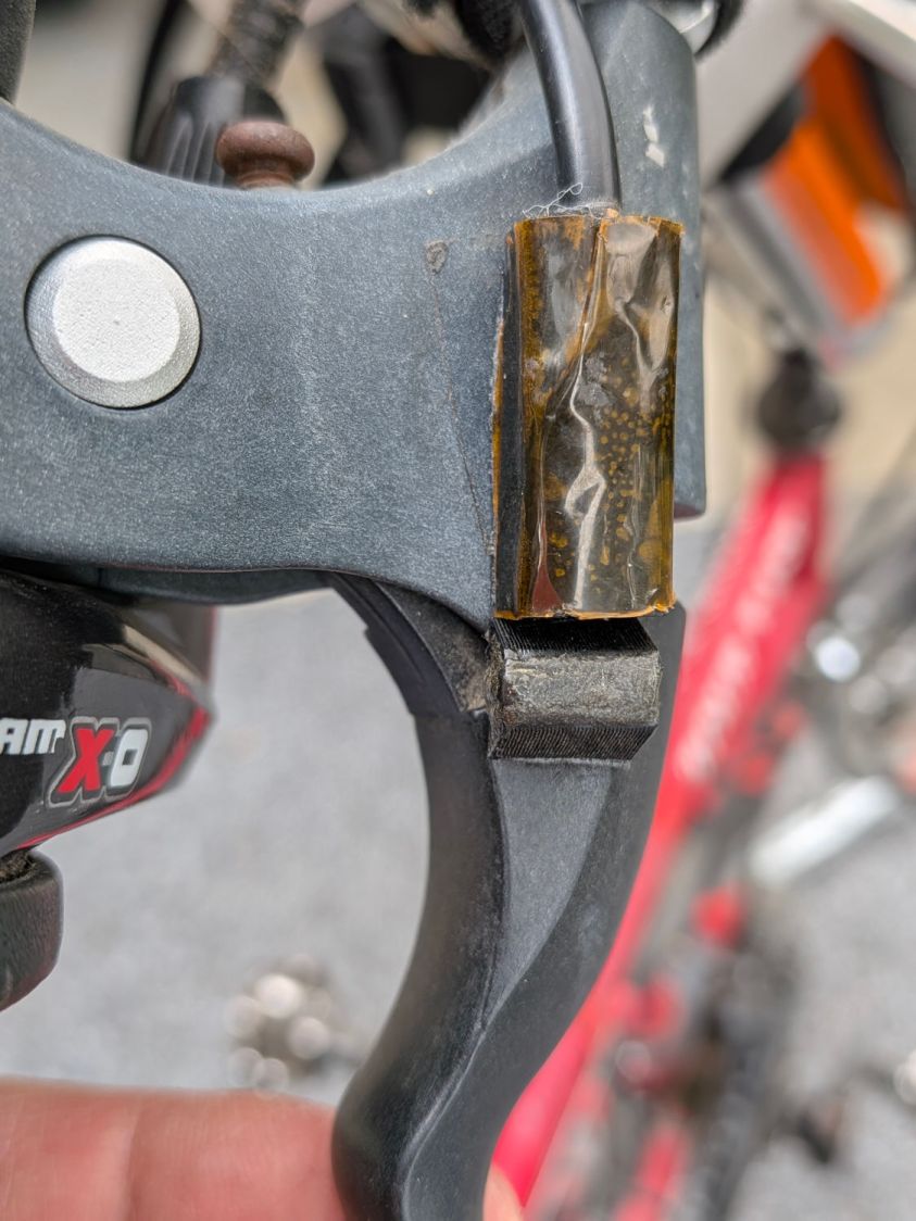
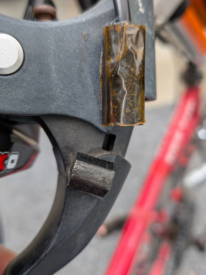
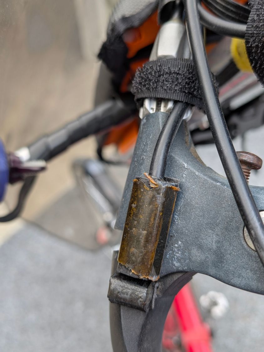
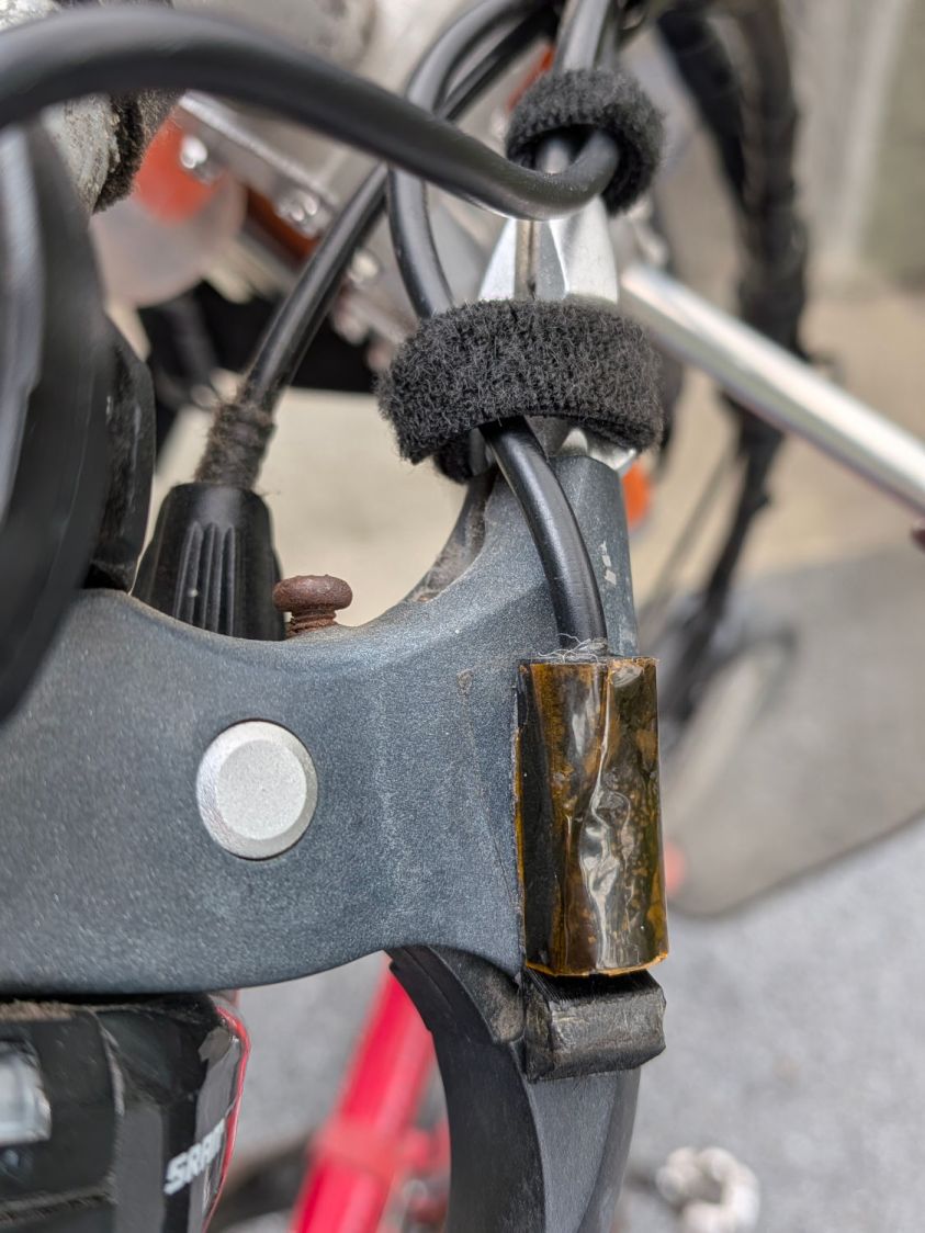
    The magnets come from power toothbrush heads, encased in urethane adhesive in 3D printed mounts.

    Stipulated: I sometimes over-do things.

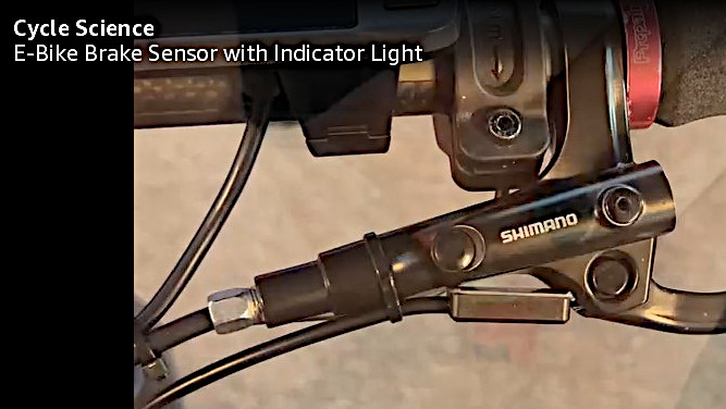
    However, I am absolutely not going to back down from saying the lashup shown in this screen grab from the sensor installation video is utterly and completely wrong:

    E-bike Brake Sensor - suggested installation
    E-bike Brake Sensor – suggested installation

    Do not get me started, you know how I am. OK?

  • E-Bike Brake Sensor Bench Check

    E-Bike Brake Sensor Bench Check

    A pair of brake sensors with LED indicators arrived and should improve the situation on Mary’s bike.

    The connector pinout, as seen looking into the jack on the controller side of the cable:

    Bafang Brake Sensor pinout
    Bafang Brake Sensor pinout

    Of course, one cannot depend on color codes, but now we know it uses a 5 V supply. Some rummaging produced a suitable (“Julet”) connector, a cutoff USB cable, and a USB power supply:

    Tour Easy LED brake sensor - bench test harness
    Tour Easy LED brake sensor – bench test harness

    You’ll note the sensor’s signal wire is blue, not white, but red = 5 VDC and black = common on both sides of the splice. This is not to be sniffed at.

    With the disk magnet (supplied with the sensors) oriented edgewise to the sensor, so the magnetic field is largely cancelled, the maximum separation allowing the sensor to remain On is about 7 mm:

    Tour Easy LED brake sensor - edge - max ON
    Tour Easy LED brake sensor – edge – max ON

    The minimum distance allowing it to be Off is 8 mm:

    Tour Easy LED brake sensor - edge - min OFF
    Tour Easy LED brake sensor – edge – min OFF

    Orienting the disk face-on to the sensor increases the distances, because the magnetic field is not cancelled out in that direction. Similarly, positioning the magnet either above or below the plane of the sensor changes the results.

    The maximum On distance is now 20 mm:

    Tour Easy LED brake sensor - side - max ON
    Tour Easy LED brake sensor – side – max ON

    The minimum Off distance is 22 mm:

    Tour Easy LED brake sensor - side - min OFF
    Tour Easy LED brake sensor – side – min OFF

    The other magnet has a similar field strength and the other sensor responds at nearly the same distances, so they’re reasonably matched.

    The LEDs are, however, not well matched: one sensor is much brighter than the other. I only have one connector, so I cannot show both in the same picture. These pictures have the same exposure (1/120 s and f/1.7), with the top sensor appearing in the previous pictures:

    E-bike Brake Sensors - LED Brightness comparison
    E-bike Brake Sensors – LED Brightness comparison

    The red LEDs show a similar difference. I’m certain this doesn’t rise to the level of a warranty claim, because, hey, maybe the brighter one should be dimmer.

    Now, to fit them on Mary’s bike …

  • Bafang Brake Sensor Magnet Re-Re-Realignment

    Bafang Brake Sensor Magnet Re-Re-Realignment

    Several years and realignments later, the brake sensors on Mary’s Tour Easy became slightly mobile on the foam tape holding them to the brake lever mounts and, of course, anything affecting the sensor position relative to the magnet inevitably makes it overly sensitive to the brake lever position.

    For unknown reasons, the DPC-18 displays devote zero pixels to the brake sensor status, so the only indication of a brake sensor being active is when the motor cuts out. This is not to be tolerated, particularly in traffic, so both the sensors and their magnets are now remounted on fresh tape with careful attention to proximity.

    The magnet is snugged against the sensor when the lever is released:

    Tour Easy brake sensor gap - released
    Tour Easy brake sensor gap – released

    The activation point is about a third of the way to the fully pulled position:

    Tour Easy brake sensor gap - braking
    Tour Easy brake sensor gap – braking

    I would prefer having the magnet move parallel to the sensor’s long axis, but that’s just not the way these levers work.

    The left-side sensor cable is now snugged to the brake cables to keep it out of harm’s way as she installs & removes the water reservoir on the handlebars under the fairing:

    Tour Easy brake sensor cable - left
    Tour Easy brake sensor cable – left

    For symmetry, the right-side sensor cable sports a similar tiedown:

    Tour Easy brake sensor cable - right
    Tour Easy brake sensor cable – right

    Having recently discovered brake sensors with integral LED status indicators, I plan to update that whole mess in the near future.

  • July 4 2026: Deadfall

    July 4 2026: Deadfall

    Heavy winds during an overnight storm on July 4 2026 brought trees down across Dutchess County and caused widespread power outages. Our little generator justified its existence by preserving our food for about 24 hours, but other folks were without power for three or four days.

    A large branch fell across the Carriage Hill entrance:

    Carriage Hill Bridge - treefall - 2026-07-07
    Carriage Hill Bridge – treefall – 2026-07-07

    The terrain and lot layout in Carriage Hill often requires heavy equipment for tree maintenance:

    Tree Clearing Crane
    Tree Clearing Crane

    Many trees along the Dutchess Rail Trail toppled as their root balls rotated or simply broke off:

    Rail trail north - treefall B - 2026-07
    Rail trail north – treefall B – 2026-07

    Others snapped and took out the fences:

    Rail trail north - treefall A - 2026-07
    Rail trail north – treefall A – 2026-07

    We ride as far from this deadfall as we can:

    Rail trail south - treefall - 2026-07
    Rail trail south – treefall – 2026-07

    Cleanup continued for weeks and we wish the crews well.

  • Sharing the Road on Raymond Avenue: Passing Gas

    Sharing the Road on Raymond Avenue: Passing Gas

    The NYS DOT engineer who designed the Raymond Avenue rebuild told me drivers should drive on the median to give cyclists enough clearance. This rarely occurs, because the “design” put bollards / posts / road furniture just behind the curb where they both deter driving and are easily hit.

    The July 4th power outage called for refilling the gasoline supply and I’m returning home along Raymond Avenue:

    Tour Easy - Passing Gas on Raymond - 2026-07-08
    Tour Easy – Passing Gas on Raymond – 2026-07-08

    That’s generous clearance, particularly from a hulking pickup truck. FWIW, commercial drivers generally do much better than average civilians.

    If towing the trailer weren’t such a nuisance, I’d deploy a decorative gas can on every ride.

  • Power Switch Mollyguards

    Power Switch Mollyguards

    It turns out that dragging a USB cable across the top of the UPS for the PC (about to be) running the Sherline mill was enough to flip its flush-mounted hairtrigger power switch. Although I can’t recess the switch, adding a mollyguard should help:

    Mollyguard - UPS power switch
    Mollyguard – UPS power switch

    The power switches on the new outlet strips also seem unduly sensitive and a preemptive strike seemed in order:

    Mollyguard - outlet strip switch
    Mollyguard – outlet strip switch

    Two layers of 3 mm acrylic just barely clear the switch, but should prevent casual trips. AFAICT, the little hexagonal shape fills the hole for an indicator LED this strip doesn’t have.

    Yellow acrylic is deliberately more conspicuous than the bike control mollyguard.

  • BOB Yak Trailer: Fender Front Mount

    BOB Yak Trailer: Fender Front Mount

    I eventually tracked a distressingly loud rattle from the BOB Yak trailer to a fender mount failure:

    BOB Yak Trailer fender front mount - aluminum fatigue
    BOB Yak Trailer fender front mount – aluminum fatigue

    The screw clamped the round aluminum fender between two flat washers (the other of which has been touring the workbench). The hole in the aluminum started as a screw slot and eventually fretted away around the edge of the washers, leaving a trapped fragment to fall out as I loosened the screw.

    Well, this mount lasted a decade longer than the wire mount at the top of the fender, so there’s that.

    As before, a bit of math conjures a chunky mount from the vasty digital deep:

    Fender front mount - solid model - Show view
    Fender front mount – solid model – Show view

    The first iteration didn’t have the hole for the threaded insert angled downward at 10°, but it’s easier to make better measurements with a “pretty close” prototype. I’m reasonably sure the angle is a glitch due to hand-brazing the frame tubes, but we’ll never know.

    The inner plate angles to match the insert, thus keeping the screw & washer perpendicular to the surface:

    Fender front mount - solid model - Mounts view
    Fender front mount – solid model – Mounts view

    A brim around that chip of plastic ensures a good grip on the platform:

    BOB Yak Trailer - fender front mount - PrusaSlicer preview
    BOB Yak Trailer – fender front mount – PrusaSlicer preview

    I suppose rounding the corners would make it prettier:

    BOB Yak Trailer fender front mount - inner plate
    BOB Yak Trailer fender front mount – inner plate

    The original screw was slightly too short, so that’s a shiny replacement from the Drawer o’ Random M5 Screws. If I ever have occasion to go in there again, I’ll use a button head screw, although there’s certainly enough clearance:

    BOB Yak Trailer fender front mount - tire clearance
    BOB Yak Trailer fender front mount – tire clearance

    From the top, the gray PETG-CF looks like it grew there:

    BOB Yak Trailer fender front mount - installed
    BOB Yak Trailer fender front mount – installed

    I figured the mount’s radius by feeding measurements into the chord equation and assuming the overall curve is circular; the radius came out slightly too large, which likely won’t make much difference.

    The OpenSCAD source code as a GitHub Gist:

    // BOB Yak Trailer – fender front mount
    // Ed Nisley – KE4ZNU
    // 2026-06-15
    include <BOSL2/std.scad>
    Layout = "Show"; // [Build,Show,Frame,Fender,OuterMount,InnerMount,Mounts]
    /* [Hidden] */
    ID = 0;
    OD = 1;
    LENGTH = 2;
    HoleWindage = 0.2;
    Protrusion = 0.01;
    NumSides = 4*3*2*4;
    Gap = 5.0/2;
    $fn=NumSides;
    WallThick = 5.0;
    Washer = [6.0,16.0,1.5]; // M5 fender washer
    Rivnut = [5.0,10.3,1.5]; // M5 rivnut in frame
    FrameOD = 16.1; // trailer frame tubing
    FrameAngle = 10;
    FenderOA = [52,440,1.5]; // minor major thickness
    BlockOA = [0,40.0,1.25*Washer[OD]];
    //—–
    // Define things
    // Relevant part of the trailer frame
    // origin at center of rivnut
    module Frame() {
    yrot(FrameAngle)
    union() {
    left(Rivnut[LENGTH])
    ycyl(2*BlockOA.y,d=FrameOD,anchor=RIGHT);
    xcyl(FrameOD/2,d=Rivnut[OD],anchor=RIGHT);
    left(Protrusion)
    xcyl(10,d=Rivnut[OD],anchor=LEFT);
    }
    }
    module OuterFender() {
    torus(od=FenderOA[OD],d_min=FenderOA[ID],orient=FRONT,anchor=LEFT);
    }
    module FullFender() {
    difference() {
    OuterFender();
    right(FenderOA[LENGTH]) // make it a cup
    torus(od=FenderOA[OD] – 2*FenderOA[LENGTH],d_min=FenderOA[ID] – 2*FenderOA[LENGTH],
    orient=FRONT,anchor=LEFT);
    right(FenderOA[ID]/2) // remove inner half
    ycyl(2*BlockOA.y,d=FenderOA[OD] – FenderOA[ID],anchor=LEFT);
    down(2*Washer[OD]) // remove bottom part
    cuboid(2*[FenderOA[OD],FenderOA[OD],FenderOA[OD]],anchor=TOP+LEFT);
    }
    }
    module OuterMount() {
    difference() {
    right(FenderOA[ID]/2)
    cuboid([FrameOD/3 + Washer[LENGTH] + FenderOA[ID]/2,BlockOA.y,BlockOA.z],
    rounding=1.0,anchor=RIGHT);
    Frame();
    OuterFender();
    }
    }
    module InnerMount() {
    difference() {
    render()
    intersection() {
    yrot(FrameAngle)
    cuboid([WallThick + FenderOA[LENGTH],BlockOA.y,BlockOA.z],anchor=LEFT);
    right(FenderOA[LENGTH])
    OuterFender();
    }
    yrot(FrameAngle)
    xcyl(FenderOA[ID],d=Washer[ID],anchor=LEFT);
    }
    }
    //—–
    // Build it
    if (Layout == "Frame") {
    Frame();
    }
    if (Layout == "Fender") {
    FullFender();
    }
    if (Layout == "OuterMount") {
    OuterMount();
    }
    if (Layout == "InnerMount") {
    InnerMount();
    }
    if (Layout == "Mounts") {
    OuterMount();
    InnerMount();
    }
    if (Layout == "Show") {
    OuterMount();
    InnerMount();
    color("Gray",0.6) {
    Frame();
    FullFender();
    }
    }
    if (Layout == "Build") {
    up(BlockOA.z/2) left(FenderOA[ID]/4)
    OuterMount();
    up(BlockOA.z/2)
    xrot(180)
    yrot(-FrameAngle)
    InnerMount();
    }