The first thing you do in any CNC milling setup is to locate the part’s origin to the spindle axis. Big mills use homing switches and carefully calibrated fixtures. I used to stick a pointy carbide scribe in a collet, push it finger-tight into the spindle, and align by eyeballometric guesstimation.
That actually works pretty well for most of my projeects, as a few mils (heck, a few dozen mils) one way or the other doesn’t make much difference.
I kept lusting after an SDA Laser Center / Edge Finder (as advertised in Home Shop Machinist), which a friend says works really well. They have a 1/4″ (6 mm) shank for smaller machines, but it’s still nigh onto three inches long and headroom is a precious commodity in a Sherline mill.
I’ve seen projects using laser pointers as alignment tools, usually with an intricate six-axis gimbal hoodickie to aim the beam in exactly the right direction. If you’ve ever sighted along the body of a hand-held laser pointer, you’ll quickly see that the laser chips and optics project the beam in a generally forward direction, but any alignment is purely coincidental.
Then I had an insight: the spindle always stays aligned along one vertical axis. The mill is firmly bolted to the table, the table to the concrete-block wall, and the floor joists overhead rest on the wall, which means a laser mounted on a floor joist could shine right down the spindle bore. Do all the fiddly alignment once, then it’ll Just Work forever after.
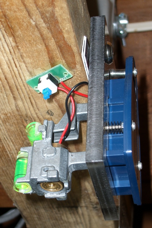
The top picture shows the result. A cheap-after-rebate (ten bucks, tops) Sears carpenter’s laser level provided the guts of the project; it’s no longer available, but you get the general idea. The fancy housing includes a cylindrical lens that converts the dot into a line, but stripping off the housing gets rid of that unwanted feature.
I carved out a plastic base plate and tapped it for 2-56 screws for fine adjustments. They fit directly in the holes that originally held the top of the housing, with springs to hold the level in position.
A plumb bob showed that the level had to live about halfway between two joists, so I screwed a scrap of 2×4″ in place and then screwed the level to that. The cardboard shims reveal the fact that the side of the board isn’t vertical, but I doubt cutting it would have helped much. After that, it’s a matter of sliding it this way & that, tweaking the screws, and fiddling around until the beam falls straight down the middle of the spindle.
The laser spot is far too large, but a small lens will do the trick. Long ago I got a sack of small lenses from a surplus outlet that included a teeny plastic lens with a 1-inch focal length. A bit of lathe work turned out a holder with a bore just a bit larger than the laser spot.
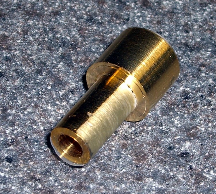
The hole trims off all the junk light around the spot itself and cuts it down to a few mm in diameter, well-centered on the spindle axis. You can’t get too skinny here, as diffraction gets in the way, but the holder bore presents a decent spot to the lens.
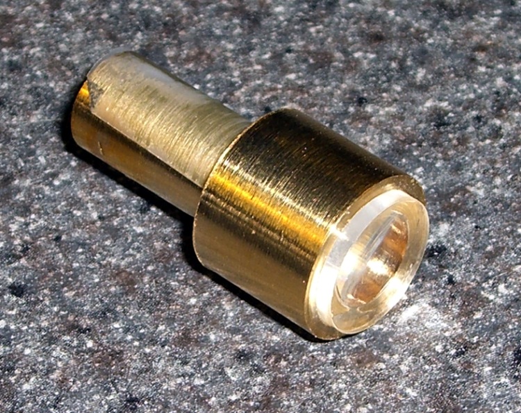
A dot or three of cyanoacrylate adhesive (I just hate the term “crazy glue”, don’t you?) holds the lens in position. As long as the lens is centered and reasonably perpendicular to the axis, it’ll work fine. The lens is much larger than the spot, so you could use one that’s even smaller than this with impunity.
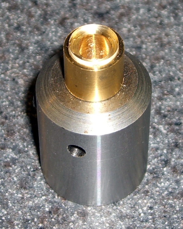
The narrow shank fits into an end mill holder, of which you should have several anyway, and the wrap of tape makes it a snug slip fit. If I hadn’t tried to get clever, the brass would be the right diameter; I keep telling myself to make another one and some day I will.
Because the beam is essentially parallel, the lens focuses it to a brilliant spot about 1 inch below the lens.
The maximum angular error (offset from the true spindle axis) is pretty small, no matter how bad a job you do, because the beam must pass through the middle of a 10-mm tube that’s 130 mm long. Assuming it’s slanted off-axis by 1 mm at the top and still makes it into the hole in the lens holder, that’s under half a degree. At the far end of the 1-inch focal length, the spot is off-position by 9 mils, call it 0.2 mm.
However, the lens focuses that beam down by a pretty good factor and reduces the error by the same factor. I don’t have the number, but in practice I think the spot size is larger than the alignment error.
You can do better than that by adding another aperture at the top of the spindle and getting really fussy with alignment.
In any event, it’s closer than I came with the carbide scriber!
Update: I mounted it on a new bracket attached to the new counterweight gantry: much better! Some tips on aligning the thing there.

Comments
12 responses to “Laser Alignment for the Sherline Mill”
All you need now is to replace the weak red laser with a hundred watts of CO2 and you could do laser cutting. ;-)
Seriously though, the idea of sending the beam down the spindle bore is one of those I wish I had thought of – very clever. And it _could_ work for a high powered beam – moving the lens will control Z, the table does X and Y, and the multi-hundred pound laser sits stationary.
The industrial laser cutting systems I’ve worked with have mostly used a static laser with a moving x/y table. They’re amazing things, swinging a 4 foot by 8 foot sheet of 1/2″ thick steel back and forth and cutting stuff out to 0.010″ tolerances. The one exception was a massive machine that tried to have both a static laser and a static workpiece and run two turning mirrors on a gantry-style system of linear ways. It never worked well, and we came to the conclusion it was because of vibration in the mirrors as they were moving.
A long time ago, I wrote the track-following code for a laser video disk: hitting a one-micron track with a one-micron beam, with the track undulating a few hundred microns at 3600 rpm. The experience gave me some real-time coding chops and a profound respect for the industrial-laser folks… plus a mild phobia for working in dark, humid, confined rooms.
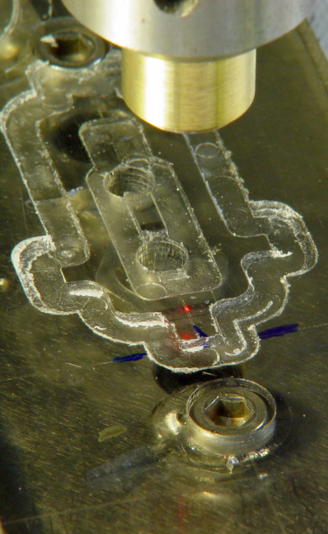
[…] aligned the spindle to the actual hinge hole with my laser aligner, a process that turned out to be surprisingly easy: note where the red dot vanishes on each side of […]
[…] in the middle, making it easy to re-clamp the acrylic from the center with a stack of washers. The laser aligner made alignment easy: make the nut finger-tight, put the spot on the left edge near the front, jog […]
[…] it down. A machinist’s square aligned the rectangle closely enough and, of course, I used the laser aligner to set the coordinate zero to the left-front […]
[…] might actually have a nice-looking defocused spot. My homebrew Orc Engineering aligner, as shown there, starts with the beam from a chip laser in a hacked carpenter’s level, so the defocused spot […]
[…] the bar up is almost trivially easy with a laser spot coming down the spindle bore. Move the table so the spot grazes the side of the bar and casts a shadow on the table, jog X to […]
[…] drilled a #50 (2-56 tap) hole in the cap pretty much by eye, using laser targeting to touch off. Laser aligning to hinge […]
[…] with their new polarizing attachment. I played with it for a while and decided that, although my crude lashup gave similar results, I just had to have a polarizing filter, […]
[…] This is a better view of the alignment process that I endure once a year when I haul my Sherline mill back from Cabin Fever. The whole thing depends on a laser level that I’ve gutted and clamped to the floor joists over the mill, as described there. […]
[…] three-jaw chuck on the Sherline table, laser-align chuck to spindle, grab shutter button by its shaft in a Jacobs chuck, grab shutter button in three-jaw chuck, […]