A red LED has a sufficiently low forward voltage to run with a MOSFET astable multivibrator and a pair of run-down AA alkaline cells:
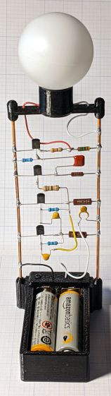
The red LED is actually part of an RGB Piranha, just to see how it compares to an as-yet-unbuilt version with a single red LED in the same package.
The LED drops 1.9 V of the 2.75 V from the mostly used-up AA cells:
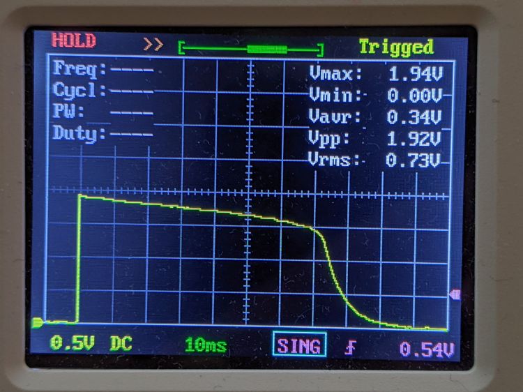
The original 33 Ω ballast resistor showed a peak current of 11 mA in a 30 ms pulse:

Replacing it with a 12 Ω resistor boosts the current all the way to 12 mA:
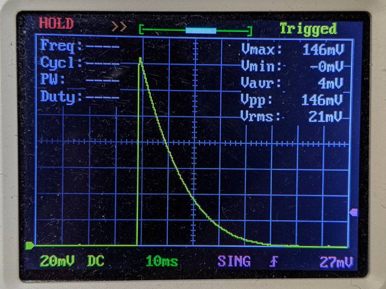
The 2N7000 gate sees a just bit more than 2 V, barely enough to get the poor thing conducting, which makes the ballast resistor mostly decorative. The MOSFET datasheet puts its 1 mA threshold somewhere between 0.8 and 3 V, so it could be worse.
Keep in mind the DSO150’s 1 MΩ input impedance sat in parallel with the 1 MΩ gate pulldown resistor forming the RC differentiator when I measured the gate voltage; I’ll leave the simulation as an exercise for the interested reader. The blinks were noticeably dimmer and perhaps a bit shorter, although eyeballometric calibration is notoriously hard.
The slightly revised schematic-layout doodle stacks the transistors along the negative bus bar:
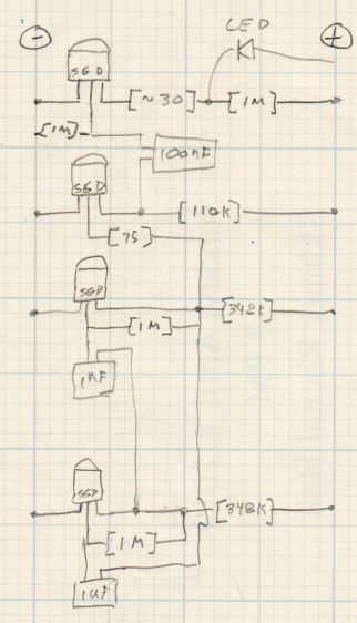
Flipping the bottom transistor over to snuggle the two timing caps next to each other would eliminate the long jumper wire and probably look better.
