-
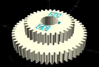
A 20-50-32-80 change gear train for a 100 TPI finish
-
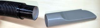
One wrap of electrical tape smaller than another crevice tool of “the same size”.
-
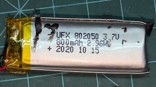
The battery has become a Spicy Pillow
-
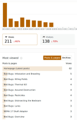
Heads-down projects that don’t produce continuous dopamine hits

-
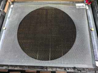
To keep both gunk and worms out of the sump
-
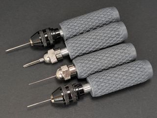
The collets have tapers ranging from 20° to 35°