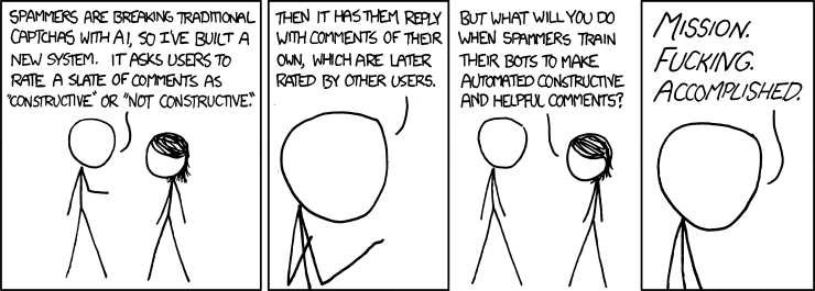
Ed Nisley's Blog: Shop notes, electronics, firmware, machinery, 3D printing, laser cuttery, and curiosities. Contents: 100% human thinking, 0% AI slop.
You can reconcile the 1/7.5 reduction in “Serving size” with the 4.7 increase in “Servings per container” by noting the latter matches the 14/3 per-serving weight ratio, not the volume ratio everybody uses. Both bags contain 5 lb of cocoa and have about the same volume; if anything, the newer bag is slightly bulkier.
However, slashing the amount of cocoa in their recipe by a factor of 3 guarantees a truly bland result. Maybe it’s just a missing “b”, a typo that could happen to anyone?
Spotted on a price scanning terminal during our grocery ride:
Price scanner update in progress
The process continued on all the scanner terminals as we collected our weekly supplies, crashed because a file was missing / locked / whatever, then became a steel-cage death match between whoever was running remote updates and Microsoft Windows:
Having verified the brake sensors work and with some idea of their actuation distances, installing them on Mary’s Tour Easy involved no more than:
Remove the fairing
Unwrap three spiral looms from All The Cables
Wrestle the Julet connectors apart
Plug in the new sensors
Stick the sensors in the proper locations
Verify proper brake operation
Rewrap the looms
Install the fairing
The “proper location” put the actuation point about halfway between the brake lever’s released and pulled positions. Given that the previous sensors lacked indicators, I don’t know where their actuation point might have been, other than likely too close to their released position.
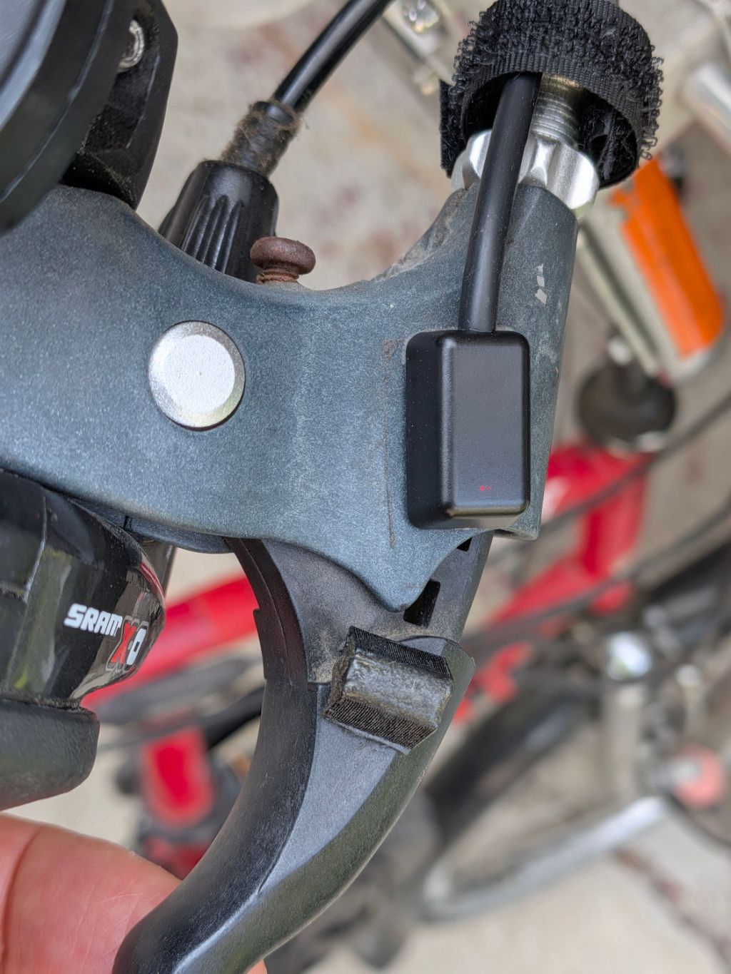
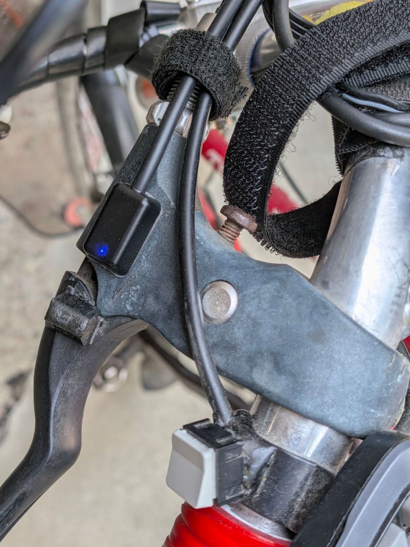
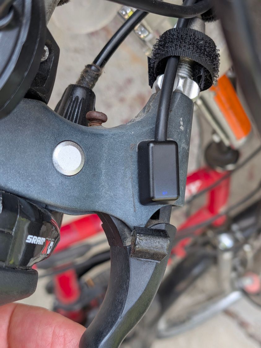
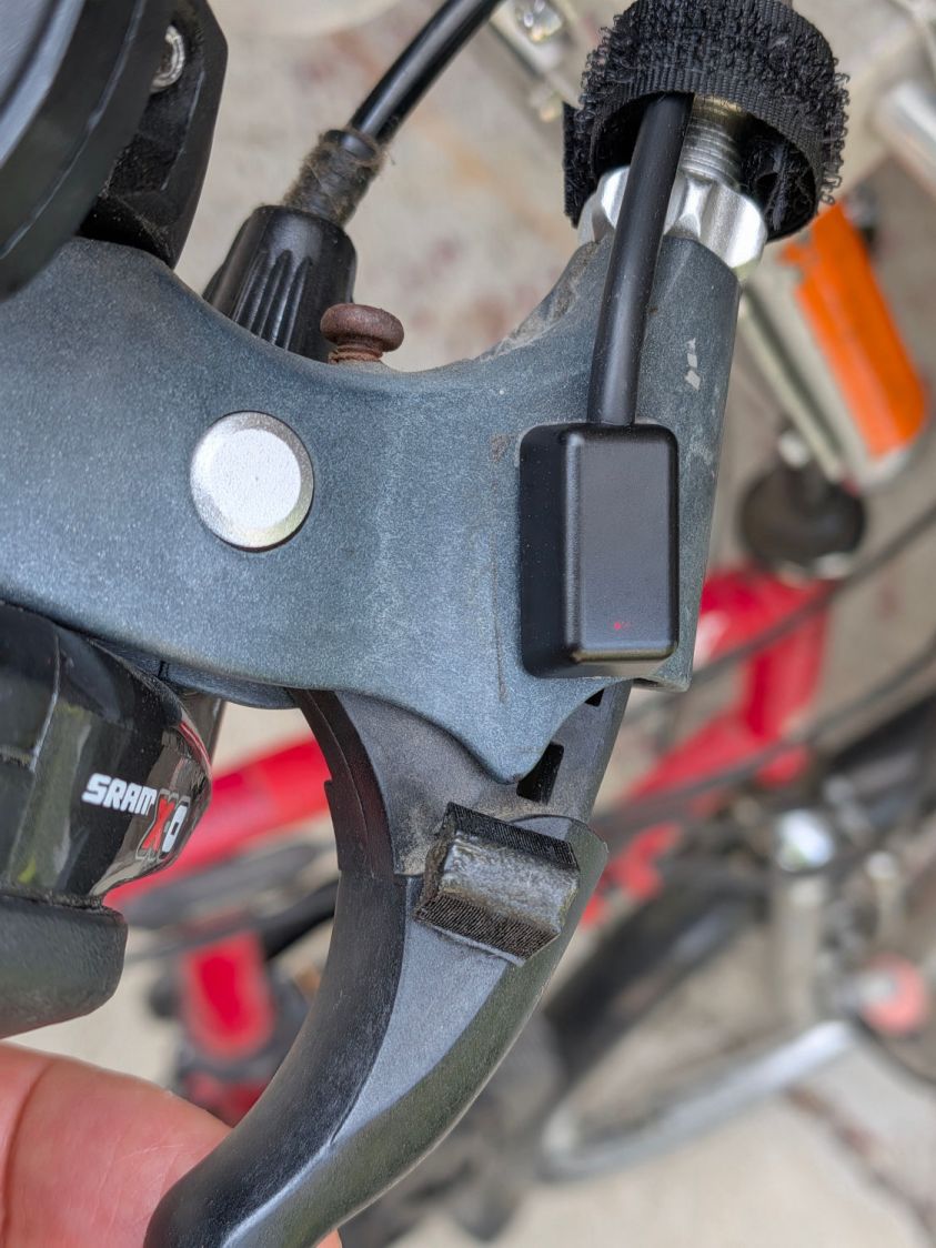
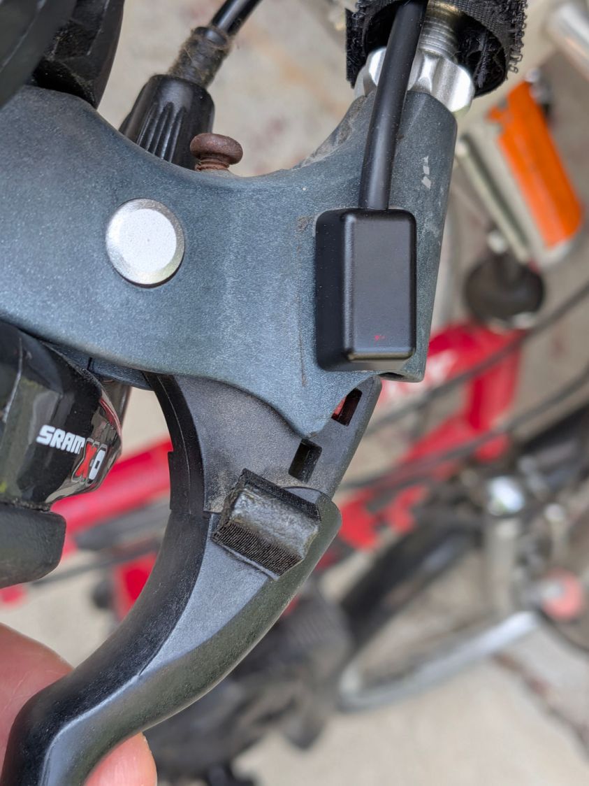
A slideshow of the front brake lever positions:
Tour Easy LED brake sensor – front released
Tour Easy LED brake sensor – front activated
Tour Easy LED brake sensor – front pulled
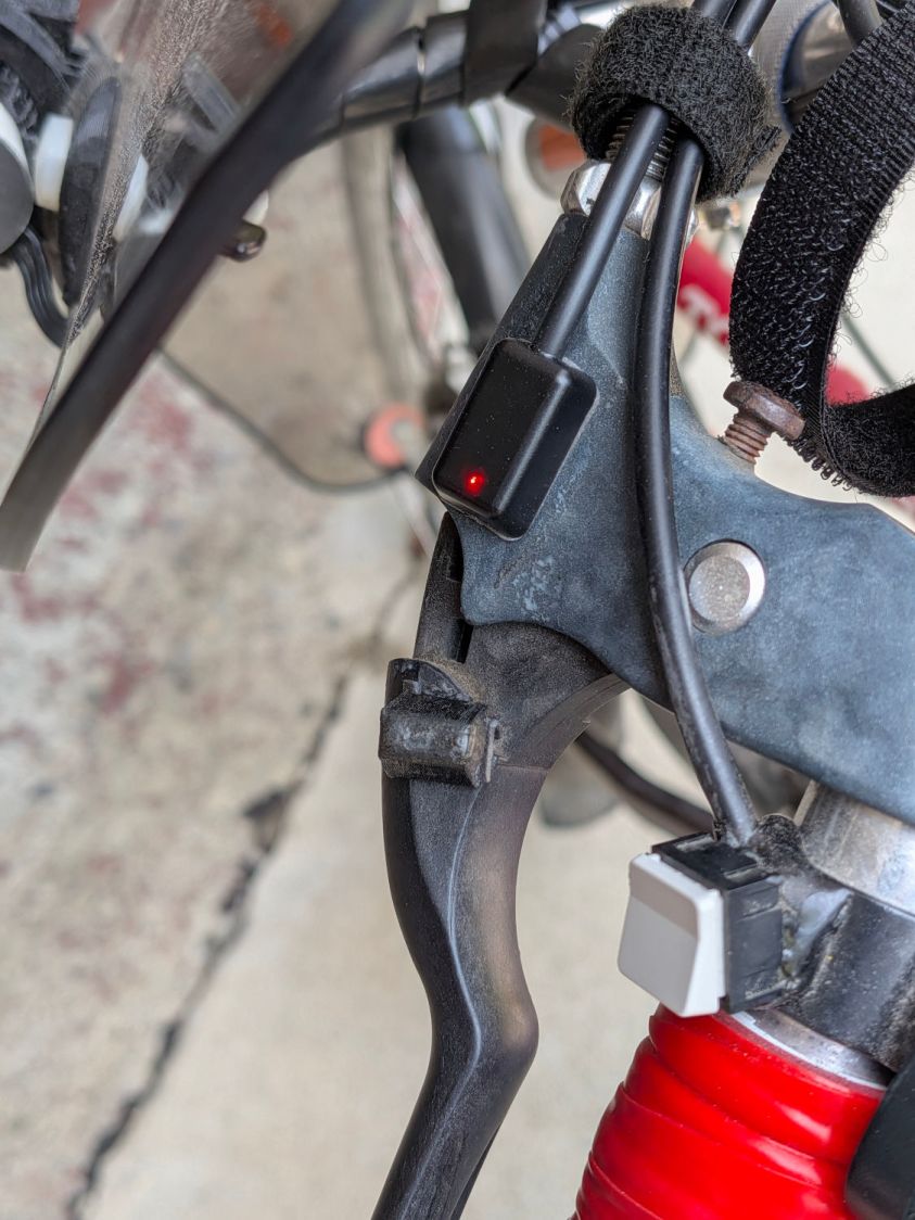
Similarly for the rear brake lever positions:
Tour Easy LED brake sensor – rear released
Tour Easy LED brake sensor – rear activated
Tour Easy LED brake sensor – rear pulled
Obviously, the rear brake lever sensor has the “dim” LEDs.
There’s not much to go wrong and the first ride was uneventful, so we’ll declare victory until the sensors or magnets shift their position, despite the wraps holding their wires to the brake cables.
The magnets come from power toothbrush heads, encased in urethane adhesive in 3D printed mounts.
Stipulated: I sometimes over-do things.
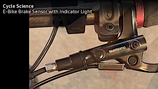
However, I am absolutely not going to back down from saying the lashup shown in this screen grab from the sensor installation video is utterly and completely wrong:
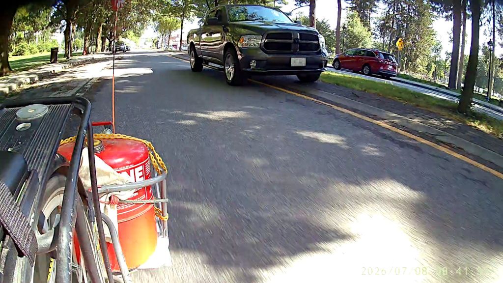
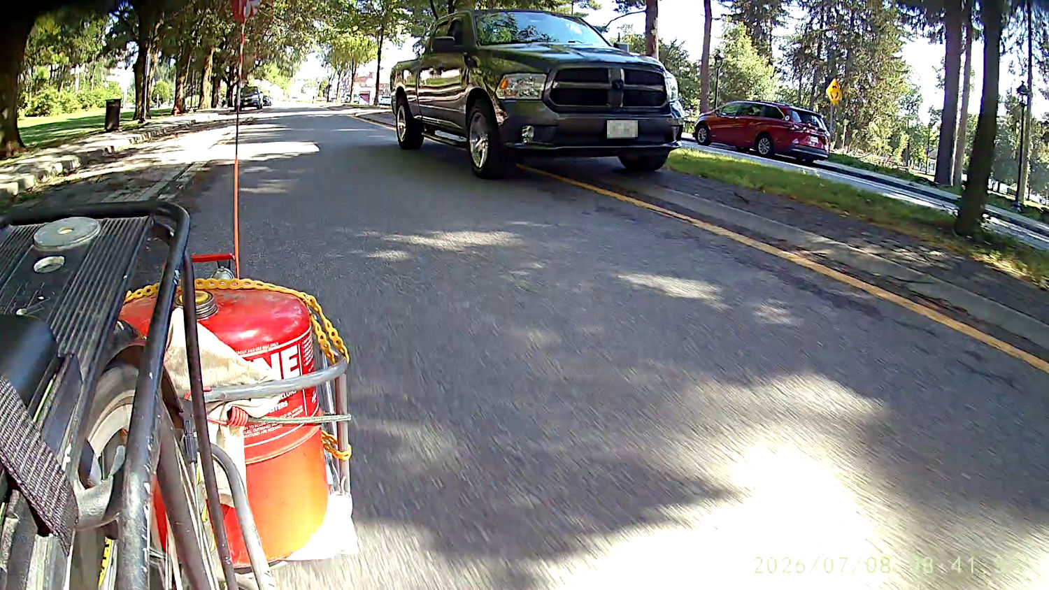
The NYS DOT engineer who designed the Raymond Avenue rebuild told me drivers should drive on the median to give cyclists enough clearance. This rarely occurs, because the “design” put bollards / posts / road furniture just behind the curb where they both deter driving and are easily hit.
The July 4th power outage called for refilling the gasoline supply and I’m returning home along Raymond Avenue:
Tour Easy – Passing Gas on Raymond – 2026-07-08
That’s generous clearance, particularly from a hulking pickup truck. FWIW, commercial drivers generally do much better than average civilians.
If towing the trailer weren’t such a nuisance, I’d deploy a decorative gas can on every ride.
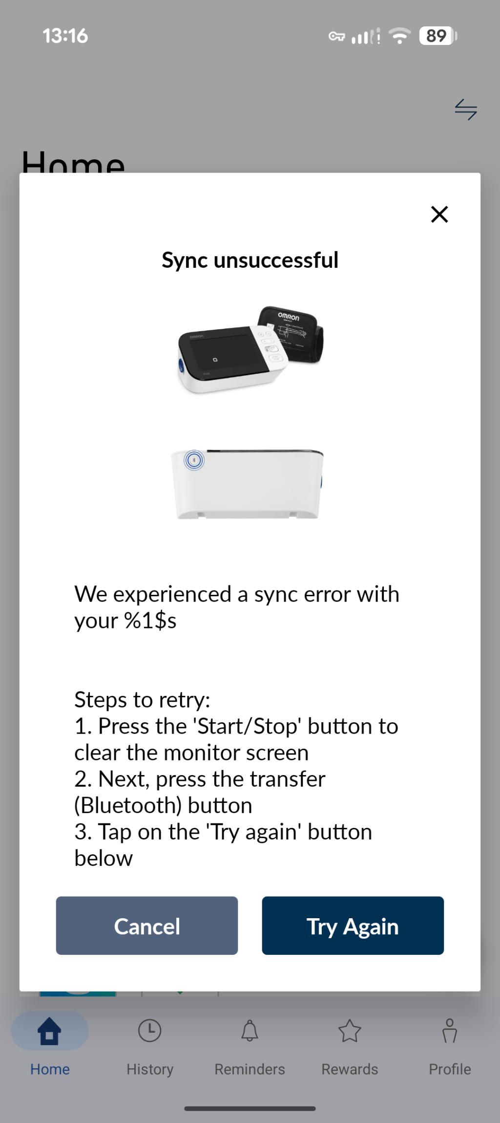
Not what you want to see when trying to extract a month’s worth of data from your blood pressure meter:
Omron – Bluetooth sync error message
Perhaps the format string should be $1$s or %1%s, not a mixture?
It’s typical for Omron to issue two updates in quick succession after months of no activity, so programming by successive approximation may be a thing.
This text reads as highly authentic human writing, likely from a personal blog or DIY/home repair journal. The author demonstrates a genuine personal voice throughout, with specific technical details that feel lived-in rather than generic. Phrases like ‘sad bent wreckage on their stems’ and ‘yet another nonstandard standard size’ carry real personality and mild frustration that feels genuinely human. The writing has a casual, matter-of-fact tone typical of someone documenting their own project for an audience of fellow hobbyists.
Yeah, that’s about right.
Of course, an AI analyzed my text and generated the response, so I tossed its response back into the hopper:
AI generation score: 72%
This text has several hallmarks of AI-generated content, particularly in its analytical, evaluative framing. It reads like an AI detector’s own output — a meta-analysis of writing rather than original creative or personal content. The language is polished and structured in a way that feels templated: it moves systematically through observations (voice, tone, specific phrases, audience) in a formulaic progression typical of AI summarization tasks. Phrases like ‘feel lived-in rather than generic’ and ‘carry real personality and mild frustration’ are the kind of hedged, evaluative language AI systems use when describing human qualities they’re trying to identify or simulate.
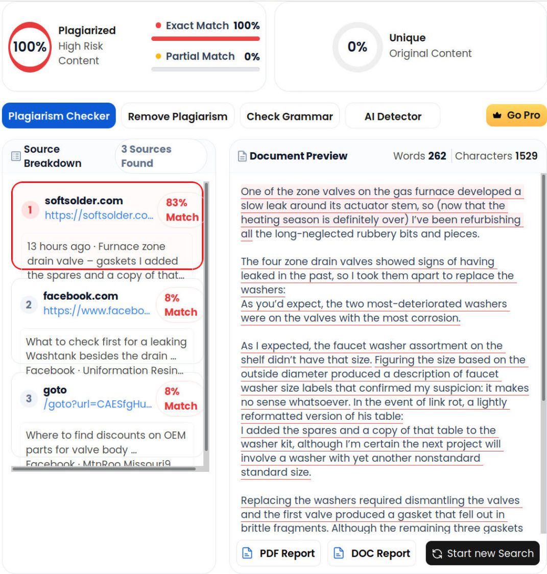
Guilty as charged: my text always exactly matches what you’ll find at softsolder.com. I have no idea where the “83% Match” for the first paragraph came from.