CNC-3018XL X-Axis Recalibration

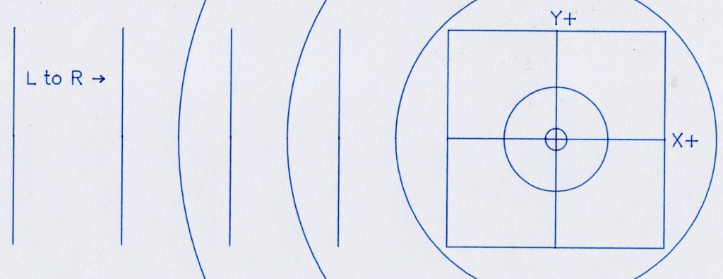
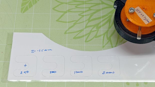
Plotting the backlash / calibration target on both the CNC-3018XL and the MPCNC quickly showed, contrary to what I expected, the MPCNC was dead-on accurate, albeit with some wobbulation and a trace of backlash:

MPCNC - Backlash test - detail
MPCNC – Backlash test – detail

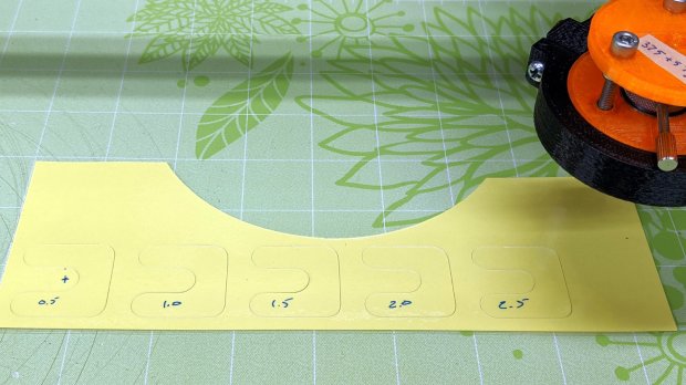
Although it looks ug-u-lee, the (lower speed) drag knife cuts come out nice and, because the entry and exit moves match the main cut, the minimal backlash wasn’t a problem.

Turns out only the X axis on the 3018XL had a problem:

Cal Target - 400 step-mm - merged
Cal Target – 400 step-mm – merged

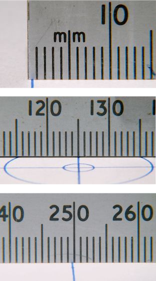
Apparently the longer leadscrew I installed as part of the “XL” conversion has a small thread pitch error: about 1 mm short in every 250 mm of travel. I don’t have any (definite, non-handwavy) method to measure the pitch directly, other than by running the follower nut and measuring the results, but it’s consistently short.

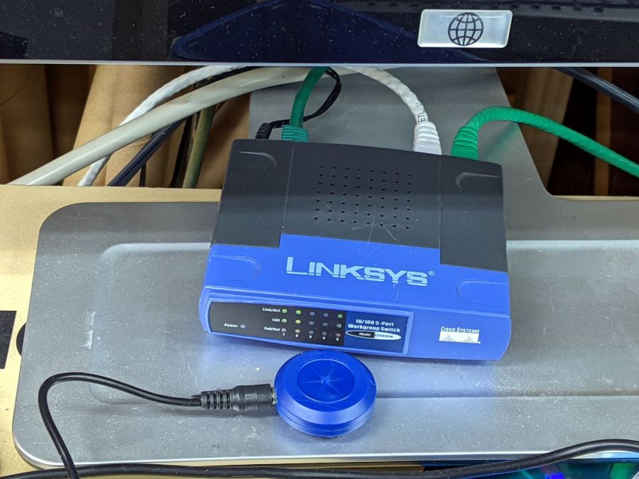
Quite some time ago (after blowing up the OEM controller board), I set up the Protoneer CNC board in 1:8 microstep mode, making the GRBL $100 setting a nice, round 400 step/mm for a two-start leadscrew with 2 mm pitch and 4 mm pitch:

400 step/mm = (200 step/rev * 8 µstep/step) / 4 mm 

After a few more measurements suggesting the leadscrew actually traveled 249.2 mm, the correct value will be:

401.28 step/mm = 400 step/mm × 250 mm / 249.2 mm

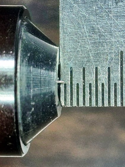
To verify I understood the problem and solution, I set $100 to a few integer values around the goal:

Cal Target - stacked - 399-402 step-mm
Cal Target – stacked – 399-402 step-mm

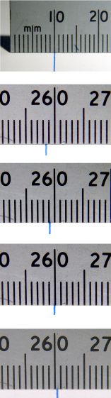
The top image shows the leftmost line at the 10 mm mark on the scale, because it’s easier for me to match the ink line with an engraved line, rather than the non-line at the end of the ruler.

The other images show the results for $100 set to 399, 400, 401, and 402 step/mm, respectively. The results last two results bracket the desired 250 mm outcome, with 401 step/mm being Close Enough™. GRBL accepts a floating point step/mm value, so I set $100 to 401.28, but I was unable to convince myself the result came out consistently different than 401.00.

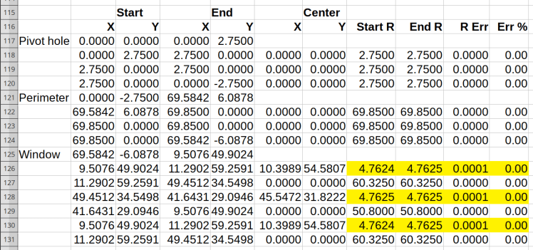
Plotting both the tick marks (green) and the knife path (red) on the 3018XL, then cutting the bare paper on the MPCNC, showed the two machines now agree on where the knife should fall. The outer end of the tick marks extends 1 mm beyond the cut line to ensure small misalignments do not produce an obvious white gap around the edge of the deck.

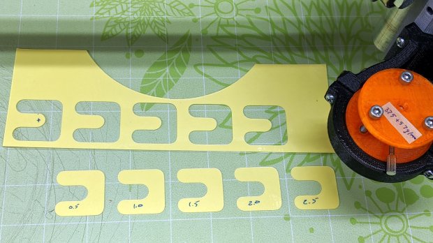
The Y axis continues to match:

Tek CC - 2022-02-14 - Y detail
Tek CC – 2022-02-14 – Y detail

And now the X axis looks just as good:

Tek CC - 2022-02-14 - X detail
Tek CC – 2022-02-14 – X detail

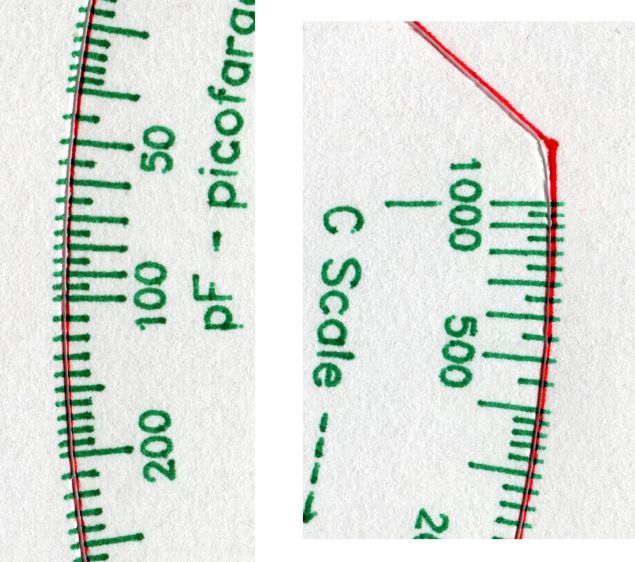
The drag knife corners are rounded, as you’d expect. The cut seems slightly offset from a small origin touch-off error, but the scales now match.

GCMC XY Axis Calibration Target

The CNC-3018XL drawing the scales on a Tek Circuit Computer disagreed with the MPCNC cutting the perimeter. The Y axis edges looked OK:

Tek CC - 2021-11 - Y detail
Tek CC – 2021-11 – Y detail

But the cut on the X axis edges went too close to the tips:

Tek CC - 2021-11 - X detail
Tek CC – 2021-11 – X detail

I conjured a calibration target to help measure the two machines:

Cal Target - CNC3018XL
Cal Target – CNC3018XL

The X- side of the plot gives the general idea:

CNC-3018XL - Backlash Test - 400step-mm
CNC-3018XL – Backlash Test – 400step-mm

The vertical lines consist of two halves, drawn in order from left to right on the top and right to left on the bottom, meeting in the middle at the Y=0 axis. If they do, in fact, meet in the middle, then there’s no problem with backlash.

The 25 mm distance between adjacent lines verifies the linear calibration; the total distance along the X and Y axes provides more travel for more error accumulation.

The circles provide some reassurance the machine can draw a smooth circle, because they come from GRBL’s (or whatever) G2 G-Code commands, not a linear approximation.

Spoiler: after a considerable amount of drawing, measuring, and muttering, the problem emerged from the CNC-3018XL’s X-axis leadscrew:

Cal Target - 400 step-mm - merged
Cal Target – 400 step-mm – merged

It’s half a millimeter short on each end!

More on this tomorrow …

The GCMC source code as a GitHub Gist:

(epilog begins)
(bCNC may regard plot as done before this returns)
M2
(epilog ends)
view raw epilog.gcmc hosted with ❤ by GitHub
(prolog begins)
G17 (XY plane)
G21 (mm)
G40 (no cutter comp)
G49 (no tool length comp)
G80 (no motion mode)
G90 (abs distance)
G94 (units per minute)
(prolog ends)
view raw prolog.gcmc hosted with ❤ by GitHub
// Grid pattern to check XY scaling
// Ed Nisley KE4ZNU - 2021-11
// gcmc -P 4 --pedantic --prolog prolog.gcmc --epilog epilog.gcmc --output 'Scale Grid.ngc' 'Scale Grid.gcmc'
include("engrave.inc.gcmc");
FALSE = 0;
TRUE = !FALSE;
//-----
// Define useful constants
SafeZ = [-,-,10.0mm]; // above all obstructions
TravelZ = [-,-,2.0mm]; // within engraving / milling area
PenZ = [-,-,-1.0mm]; // depth for good inking
PenSpeed = 2000mm;
//-----
// Overall values
PlotSize = [250mm,200mm,-];
comment("PlotSize: ",PlotSize);
GridSize = [25mm,25mm,-];
Margins = [5mm,5mm,-];
CenterOD = 5.0mm;
TextFont = FONT_HSANS_1_RS; // single stroke stick font
TextSize = 3.0 * [1.0mm,1.0mm];
//-----
// Draw it
feedrate(PenSpeed);
comment("Draw title info");
tp = scale(typeset("Scale & Backlash Test Pattern",TextFont),TextSize);
tp += [-PlotSize.x/2 + GridSize.x/2,PlotSize.y/2 - GridSize.y/2,-];
engrave(tp,TravelZ.z,PenZ.z);
tp = scale(typeset("Grid " + GridSize,TextFont),TextSize);
tp += [-PlotSize.x/2 + GridSize.x/2,PlotSize.y/2 - GridSize.y/2 - 1.5*TextSize.y,-];
engrave(tp,TravelZ.z,PenZ.z);
tp = scale(typeset("F " + PenSpeed + "/min",TextFont),TextSize);
tp += [-PlotSize.x/2 + GridSize.x/2,PlotSize.y/2 - GridSize.y/2 - 3.0*TextSize.y,-];
engrave(tp,TravelZ.z,PenZ.z);
tp = scale(typeset("Ed Nisley - KE4ZNU",TextFont),TextSize);
tp += [-PlotSize.x/2 + GridSize.x/2,-(PlotSize.y/2 - GridSize.y/2),-];
engrave(tp,TravelZ.z,PenZ.z);
tp = scale(typeset("softsolder.com",TextFont),TextSize);
tp += [-PlotSize.x/2 + GridSize.x/2,-(PlotSize.y/2 - GridSize.y/2 + 1.5*TextSize.y),-];
engrave(tp,TravelZ.z,PenZ.z);
comment("Mark center point");
goto(SafeZ);
goto([CenterOD/2,0,-]);
move(PenZ);
circle_cw([0,0]);
comment("Label axes");
tp = scale(typeset("X+",TextFont),TextSize);
tp += [GridSize.x + 0.5*TextSize.x,-TextSize.y/2,-];
engrave(tp,TravelZ.z,PenZ.z);
tp = scale(typeset("Y+",TextFont),TextSize);
tp += [-TextSize.x/2,GridSize.y + 0.5*TextSize.y,-];
engrave(tp,TravelZ.z,PenZ.z);
comment("Draw left-to-right");
tp = scale(typeset("L to R →",TextFont),TextSize);
tp += [-PlotSize.x/2 + GridSize.x/2 - tp[-1].x/2,GridSize.y/2,-];
engrave(tp,TravelZ.z,PenZ.z);
goto([-(PlotSize.x/2 + Margins.x),GridSize.y,-]);
for (p=[-PlotSize.x/2,GridSize.y,-] ; p.x <= PlotSize.x/2 ; p.x += GridSize.x ) {
comment(" p: ",p);
goto(p);
move(PenZ);
move_r([-,-GridSize.y,-]);
goto(TravelZ);
}
comment("Draw right-to-left");
tp = scale(typeset("R to L ←",TextFont),TextSize);
tp += [PlotSize.x/2 - GridSize.x/2 - tp[-1].x/2,-GridSize.y/2,-];
engrave(tp,TravelZ.z,PenZ.z);
goto([(PlotSize.x/2 + Margins.x),-GridSize.y,-]);
for (p=[PlotSize.x/2,-GridSize.y,-] ; p.x >= -PlotSize.x/2 ; p.x -= GridSize.x ) {
comment(" p: ",p);
goto(p);
move(PenZ);
move_r([-,GridSize.y,-]);
goto(TravelZ);
}
comment("Draw bottom-to-top");
tp = scale(typeset("B to T ↑",TextFont),TextSize);
tp += [-GridSize.x/2 - tp[-1].x/2,-(PlotSize.y/2 - TextSize.y),-];
engrave(tp,TravelZ.z,PenZ.z);
goto([-GridSize.x,-(PlotSize.y/2 + Margins.y),-]);
for (p=[-GridSize.x,-PlotSize.y/2,-] ; p.y <= PlotSize.y/2 ; p.y += GridSize.y ) {
comment(" p: ",p);
goto(p);
move(PenZ);
move_r([GridSize.x,-,-]);
goto(TravelZ);
}
comment("Draw top-to-bottom");
tp = scale(typeset("T to B ↓",TextFont),TextSize);
tp += [GridSize.x/2 - tp[-1].x/2,(PlotSize.y/2 - 1.5*TextSize.y),-];
engrave(tp,TravelZ.z,PenZ.z);
goto([GridSize.x,(PlotSize.y/2 + Margins.y),-]);
for (p=[GridSize.x,PlotSize.y/2,-] ; p.y >= -PlotSize.y/2 ; p.y -= GridSize.y ) {
comment(" p: ",p);
goto(p);
move(PenZ);
move_r([-GridSize.x,-,-]);
goto(TravelZ);
}
comment("Draw circles");
maxr = (PlotSize.x < PlotSize.y) ? PlotSize.x/2 : PlotSize.y/2;
for (r=GridSize.x/2 ; r <= maxr ; r += GridSize.x) {
comment(" r: ",r);
goto([-r,0,-]);
move(PenZ);
circle_cw([0,0,-]);
goto(TravelZ);
}
goto(SafeZ);
goto([0,0,-]);
view raw Scale Grid.gcmc hosted with ❤ by GitHub

Raspberry Pi: WLAN to Wired Network

The CNC-3018XL and MPCNC machines each have a Raspberry Pi feeding G-Code into an Arduino clone controlling the stepper motors. The former grew a USB WiFi interface in place of its internal WiFi hardware when it seemed to have difficulty connecting to the house router, while the latter pretty much worked. Of late, however, I’ve been trying to reduce the number of WiFi devices cluttering the airwaves, with the result of wiring both machines to an old Ethernet switch from the Box o’ Network Stuff:

LinkSys Switch for CNC machines

The blue puck is the KVM button to select one of the machines for the keyboard / mouse / monitor on the bench.

One key point I generally screw up: the WiFi IP address cannot become the wired IP address without rebooting everything else on the network. Instead, just change the IP addresses and be done with it.

Collecting all the pieces in one place:

Disable the both internal WiFi hardware and Bluetooth in /boot/config.txt, thereby eliminating the need to force the WiFi down in /etc/rc.local:

dtoverlay=pi3-disable-wifi
dtoverlay=pi3-disable-bt

Define the static IP address in /etc/dhcpcd.conf:

interface eth0
static ip_address=192.168.1.34/24
static routers=192.168.1.1
static domain_name_servers=192.168.1.2

Kill IPV6 activity in /etc/sysctl.conf:

net.ipv6.conf.all.disable_ipv6=1

I very much doubt this information is either complete or correct, but it serves the purpose as of early 2022.

Drag Knife Calibration: Downforce and Speed

The drag knife faceplant suggested I must pay a bit more attention to fundamentals, so, with a 60° drag knife blade sticking out a reasonable amount, the next step is to see what effect the cutting “depth” (a.k.a. downforce) and speed have on the outcome.

A smidge of GCMC code later:

Drag Knife Cal - depth - overview - Camotics sim
Drag Knife Cal – depth – overview – Camotics sim

It’s not obvious, but each pattern steps downward by 0.5 mm from left to right. With the spring force equal to 375 g + 57 g/mm, the downforce ranges from 400 to 520 g over the five patterns.

Laminated scrap, meet drag knife:

Drag Knife Cal - Depth - as cut
Drag Knife Cal – Depth – as cut

Pulling up on the surrounding scrap left the patterns on the sticky mat:

Drag Knife Cal - Depth - extracted
Drag Knife Cal – Depth – extracted

Which suggested any cutting force would work just fine.

Flushed with success, I cut some speed variations at the minimum depth of Z=-0.5 mm = 400 g:

Drag Knife Cal - Speed - 0.5 mm - as cut
Drag Knife Cal – Speed – 0.5 mm – as cut

The blade cut through the top laminating film, the paper, and some sections of the bottom film, but mostly just scored the latter.

Repeating at Z=-1.5 mm = 460 g didn’t look much different:

Drag Knife Cal - Speed - 1.5 mm - as cut
Drag Knife Cal – Speed – 1.5 mm – as cut

However, the knife completely cut all the patterns:

Drag Knife Cal - Speed - 1.5 mm - extracted
Drag Knife Cal – Speed – 1.5 mm – extracted

As far as I can tell, the cutting speed doesn’t make much difference, although the test pattern is (deliberately) smooth & flowy like the Tek CC deck outlines. I’d been using 1000 mm/min and 2000 mm/min seems scary-fast, so 1500 mm/min may be a good compromise.

The GCMC source code as a GitHub Gist:

// Calibrate Drag Knife - speed & feed
// Ed Nisley - KE4ZNU
// 2020-03 values for MPCNC
//-----
// Dimensions
CutIncr = -0.5mm;
BottomCutZ = -2.5mm;
SpeedRatio = 2.0;
MaxSpeed = 2000mm;
MinSpeed = MaxSpeed / 8;
StripWidth = 10mm;
CornerRadius = StripWidth/2;
PatternSize = StripWidth * [3,3];
PatternSpace = 1.25;
SafeZ = 10.0mm; // above all obstructions
TravelZ = 2.0mm; // within engraving / milling area
FALSE = 0;
TRUE = !FALSE;
if (!isdefined("TestSelect")) {
TestSelect = "Depth";
}
comment("Test Selection: ",TestSelect);
//-----
// One complete pattern
// Centered at ctr, ctr.z=cut depth
function Pattern(ctr) {
local d1 = CornerRadius; // useful relative distances
local d2 = 2*d1;
local d3 = 3*d1;
local d4 = 4*d1;
goto([-,-,TravelZ]); // set up for entry move
goto(head(ctr,2) + [-d2,d3]);
move([ctr.x + d2,-,ctr.z]); // enter to cut depth
arc_cw_r([d1,-d1],d1);
move_r([0,-d4]);
arc_cw_r([-d1,-d1],d1);
move_r([-d4,0]);
arc_cw_r([0,d2],d1);
move_r([d2,0]);
arc_ccw_r([0,d2],d1);
move_r([-d2,0]);
arc_cw_r([0,d2],d1);
move_r([d4,0]); // re-cut entire entry path
goto([-,-,TravelZ]); // exit to surface
// goto(head(ctr,2));
}
//-----
// Start cutting!
goto([-,-,SafeZ]);
goto([0,0,-]);
goto([-,-,TravelZ]);
if (TestSelect == "Depth") {
comment("Depth variations");
s = MaxSpeed / 2;
feedrate(s);
c = [0,0,-]; // initial center at origin
for (c.z = CutIncr; c.z >= BottomCutZ; c.z += CutIncr) {
comment("At: ",c," speed:",s);
Pattern(c);
c.x += PatternSpace * PatternSize.x;
}
}
if (TestSelect == "Speed") {
comment("Speed variations");
c = [0,0,-2mm]; // initial center at origin
for (s = MinSpeed; s <= MaxSpeed; s *= SpeedRatio) {
comment("At: ",c," speed: ",s);
feedrate(s);
Pattern(c);
c.x += PatternSpace * PatternSize.x;
}
}
goto([-,-,SafeZ]);
goto([0,0,-]);

Drag Knife Blade Extension

The battered corner of my bench scale shows it’s been knocking around for quite a while, but the drag knife blade tip seems pretty close to the first 0.5 mm division:

Drag Knife Blade - 0.5 mm
Drag Knife Blade – 0.5 mm

The blade extends from the LM12UU holder for the MPCNC.

Scribbling the blade across a scrap of laminated yellow card stock (about 0.4 mm thick) showed it didn’t cut all the way through the bottom plastic layer, even with the spring mashed flat.

So I screwed it out to 0.7 mm:

Drag Knife Blade - 0.7 mm
Drag Knife Blade – 0.7 mm

The scale isn’t quite parallel to the blade axis and maybe it’s sticking out 0.8 mm; setting a drag knife’s blade extension obviously isn’t an exact science.

In any event, another scribble slashed all the way through the laminated deck without gashing the sacrificial cardboard atop my desk, which seems good enough.

Drag Knife Blade Lengths

The distances from the sharp tip to the top end of the edge, measured parallel to the shank axis:

  • 60° = 1.3 mm
  • 45° = 0.7 mm
  • 30° = 0.6 mm

Here, the angle goes upward from the paper / Tek CC deck / whatever to the shank axis, so the 60° blade at the top of the picture has the longest blade edge.

Drag Knife Blades - unused 60 45 30 degree
Drag Knife Blades – unused 60 45 30 degree

That’s for one trio of blades from a single eBay seller. I expected no consistency between sellers and that’s exactly what I got when I sorted my collection by peering through the microscope:

Drag Knife Blades - inconsistent cap colors
Drag Knife Blades – inconsistent cap colors

Red seems consistently 45°, but blue & yellow caps can cover either 30° or 60° blades. The actual blade angle lies mostly within ±5° of the nominal value, with 45° between 40° and 50°, but I doubt my few samples span the QA space.

The flat shaping the backside of the blade should put the point 0.25 mm from the shank axis and, because the blades are 1.0 mm ⌀, also 0.25 mm from the OD. A few spot measurements suggest the point offset can be up to 0.4 mm from the axis, so any fancy calculations you might think of making seem pretty much irrelevant.

There’s not much practical difference between the 30° (“window tint”) and 45° (“vinyl”) blades, particularly given the angle and offset tolerances, but 60° blades (“card stock”) seem better suited to cutting the 0.3 mm to 0.4 mm thick laminated Tek Circuit Computer decks than the 45° blades I’ve been using.

GRBL Error 33: Arc Coordinates vs. Decimal Places

The LinuxCNC G2/G3 arc command doc has this to say about numerical precision:

When programming arcs an error due to rounding can result from using a precision of less than 4 decimal places (0.0000) for inch and less than 3 decimal places (0.000) for millimeters.

So I normally set GCMC to produce three decimal digits, because its default of eight digits seems excessive for my usual millimeter measurements, and assume whatever G-Code sender I use won’t chop digits off the end in passing. Mistakenly setting bCNC to round at two decimal places showed what happens with fewer digits, as bCNC’s default is four decimal digits.

A closer look at the coordinates in the lower right part of the spreadsheets (from yesterday) shows the limited accuracy with two decimal digits:

Spreadsheet - GCMC 2 digit - full path - detail
Spreadsheet – GCMC 2 digit – full path – detail

The red blocks mark the first failing arc, where the relative error falls out of tolerance. If GRBL were less fussy (which it should not be), then the next arcs would proceed as shown.

Rounding to three decimal digits pushes the errors into to the third place, with the yellow highlight marking the worst errors:

Spreadsheet - GCMC 3 digit - detail
Spreadsheet – GCMC 3 digit – detail

As you should expect, the smallest arcs have the largest relative errors, although they’re now well within GRBL’s (and LinuxCNC’s, for that matter) limits.

Rounding to four decimal digits makes the errors vanishingly small:

Spreadsheet - GCMC 4 digit - detail
Spreadsheet – GCMC 4 digit – detail

So, by and large, don’t scrimp on the decimal digits … but we knew that already.

I’d been setting GRBL to produce three decimal places, but now I’m using four. Adding a few characters to each G-Code command reduces the number of commands fitting into GRBL’s buffer space, but bCNC normally keeps it around 90% full, so the path planner should remain perfectly happy.