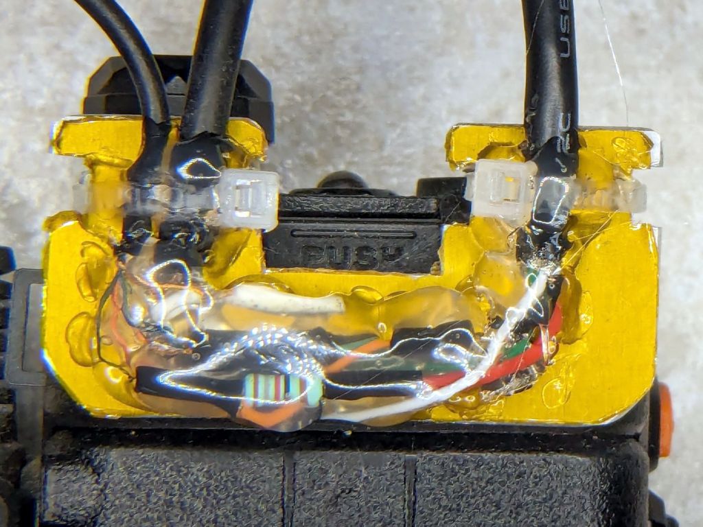
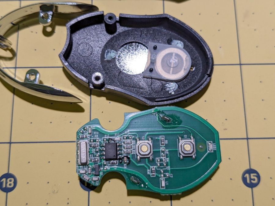
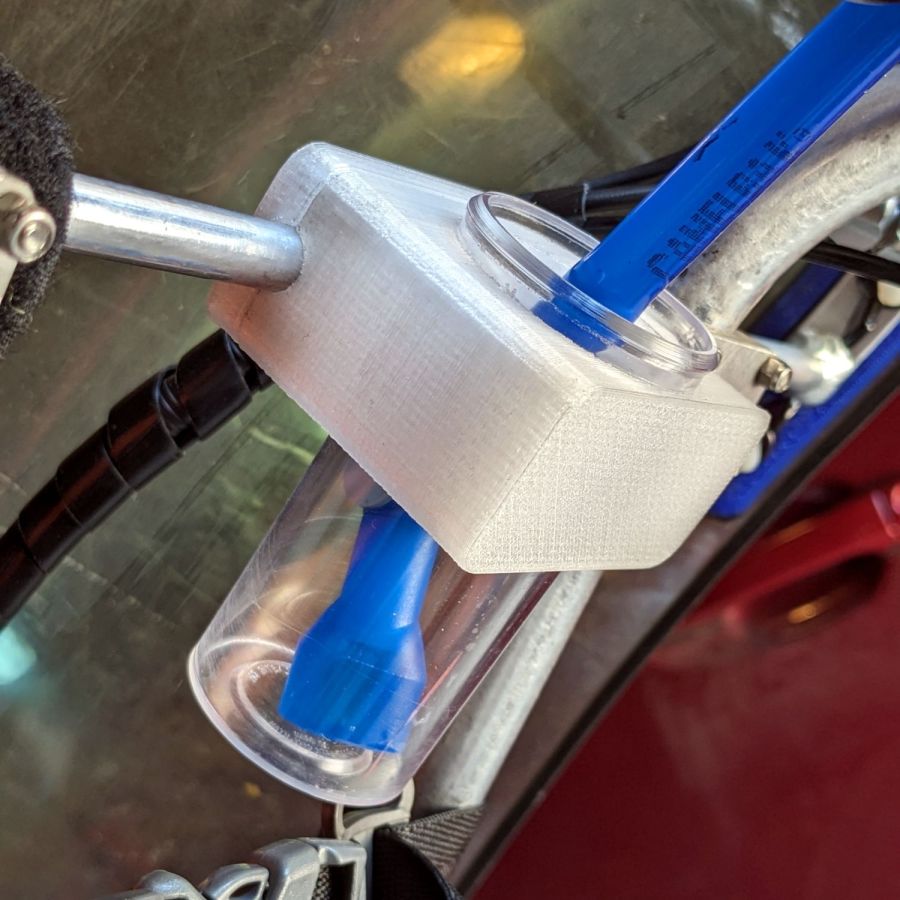
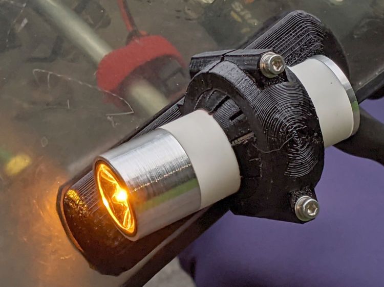
After five years and one cleaning, the PTT button on Mary’s Tour Easy became increasingly intermittent, both failing to activate solidly and sticking closed (there being nothing quite like a hot mic during a good hill climb), so it’s time for an autopsy:
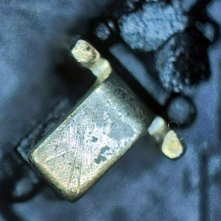
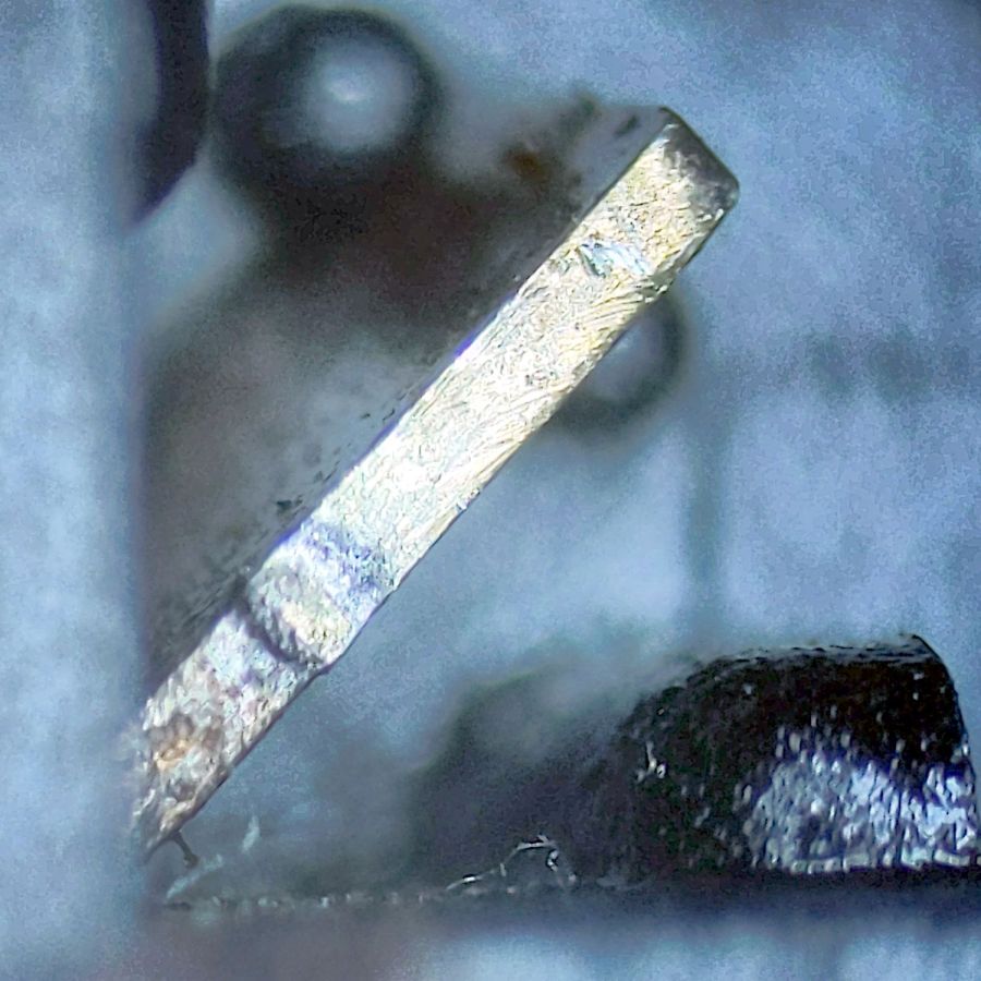
The snap dome is much more scarred at the central contact:
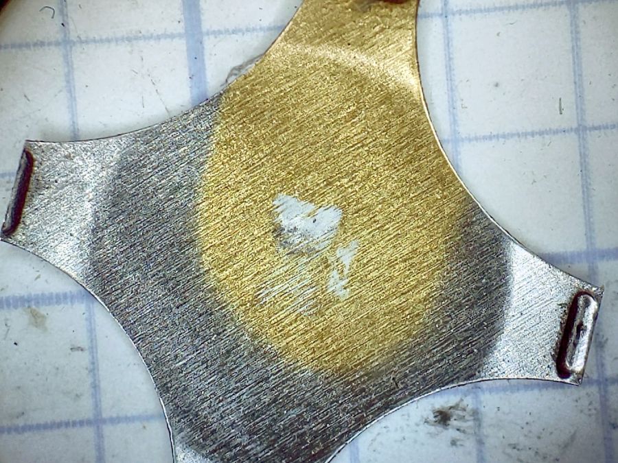
That might be a gold flash coating, but it’s pretty well worn away where it hits the central contact:
Those scratches surely happened during the previous cleaning pass, as I don’t see any way for the dome to create them.
The corner contact also shows some scuffs, along with a scar where the dome corner pivots:
All in all, though, it worked quite well.
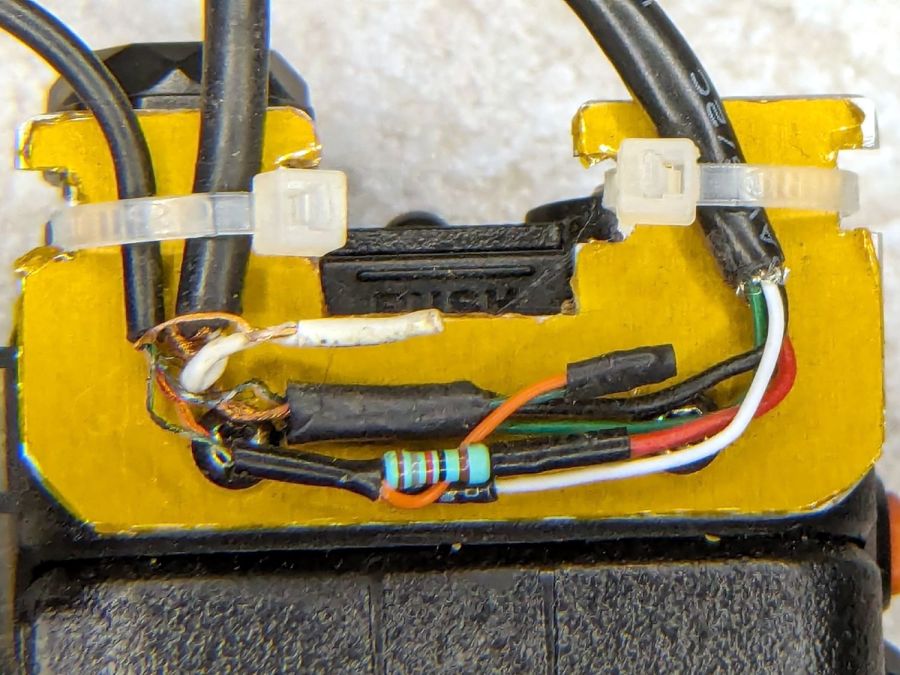
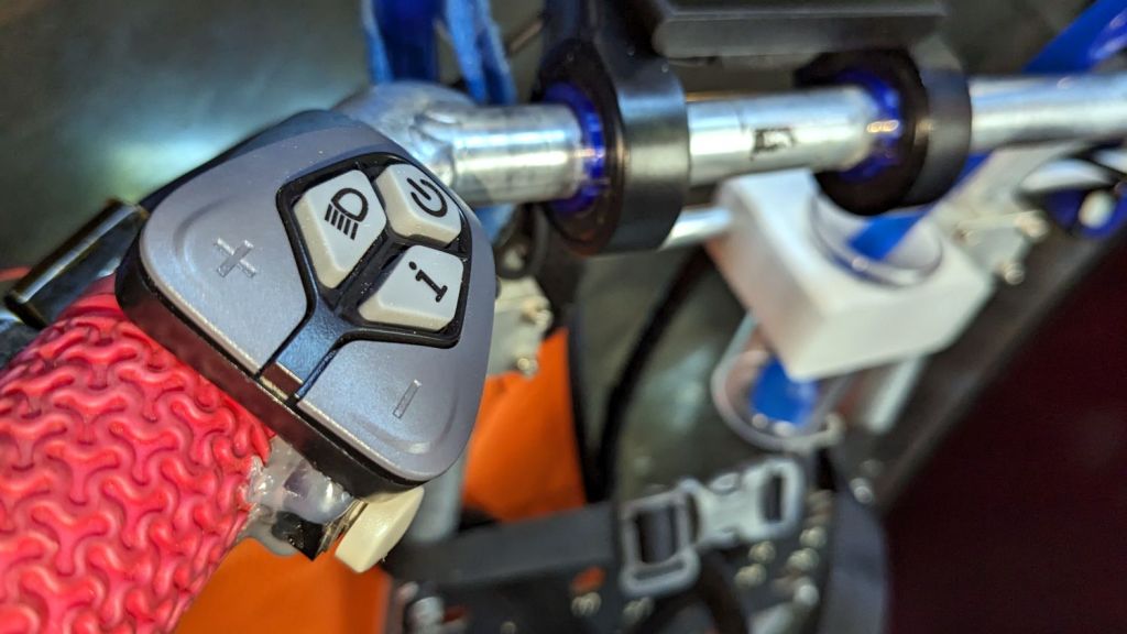
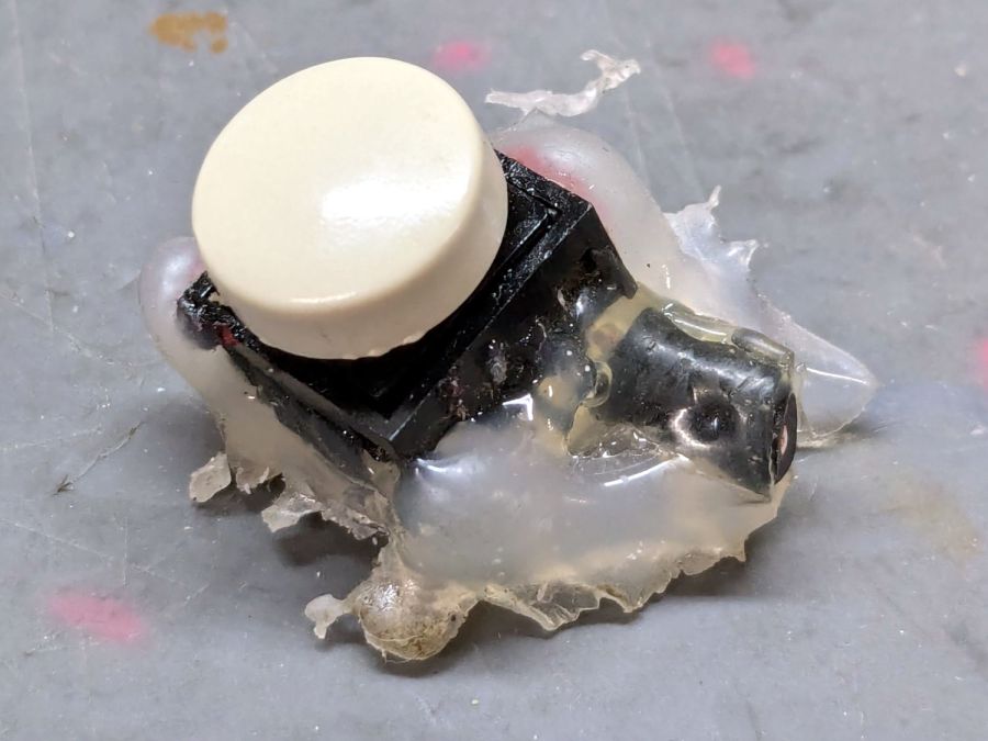
The replacement switch, also intended for indoor use on a keypad or some such device, pivots around the front edge and may be easier for her fingertip to activate:
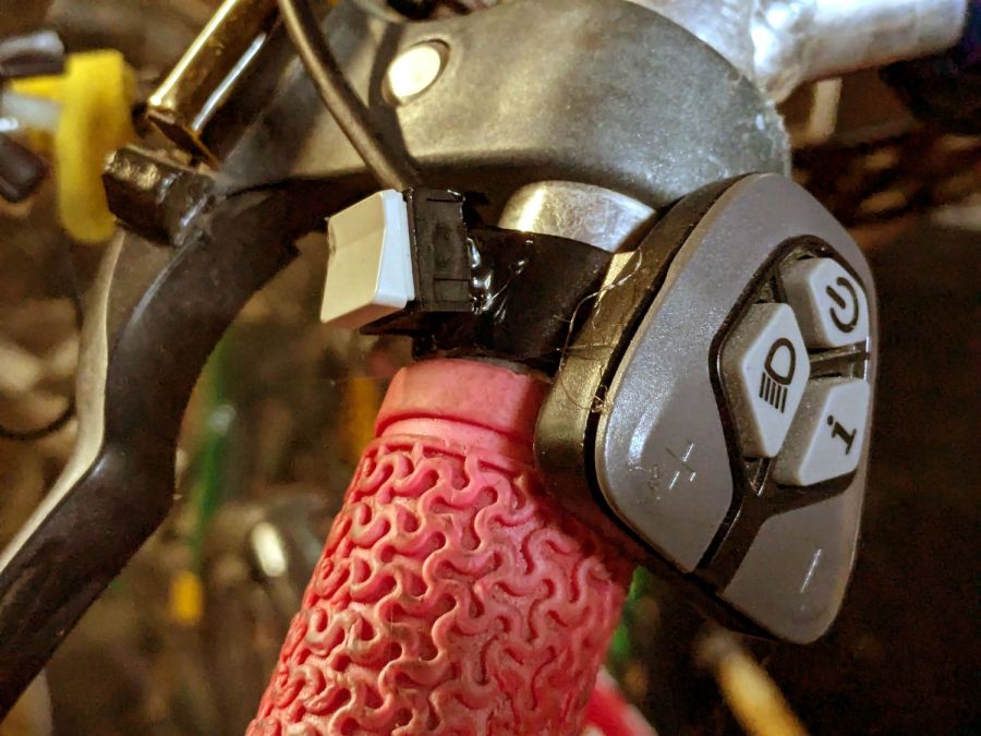
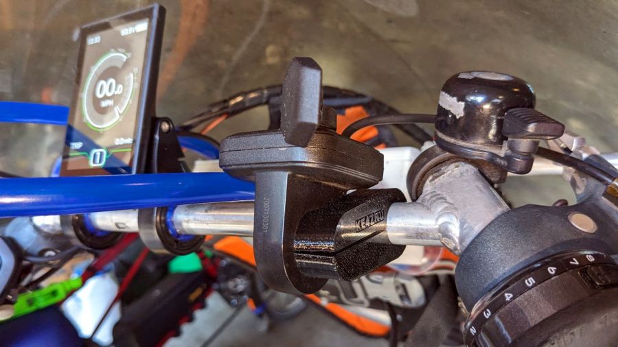
Hot melt glue seems vastly underrated for how wonderful a structural material it is.
If this one lasts five years, I’ll be perfectly happy.