Having just cleaned a bunch of gunk out of the bottom of the worm bin, we decided to try a layer of window screen to keep both gunk and worms out of the sump.
A roll of window screen Came With The House™, minus label or provenance, that felt like some sort of plastic, perhaps with a glass core.
The bin has a 19-¼ inch = 488 mm ID with 10 thin support struts around the perimeter. Laying out a circle and cutting it accurately by hand seemed like a chore, even though the screen cut easily with ordinary scissors.
The diameter just barely fit on the laser’s 700×500 mm platform, so I laid it out in LightBurn:
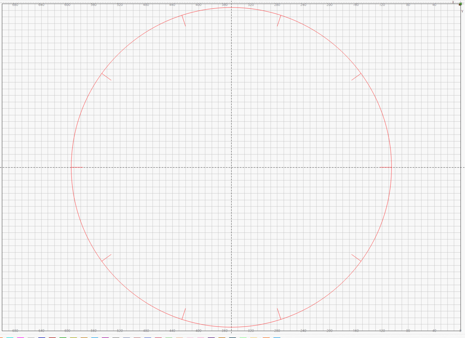
For lack of anything smarter, I applied the same setting as for the faucet gasket material (30 mm/s at 25% of 60 W) and Fired The Laser.
As far as I could tell while the laser was trundling around the circle, absolutely nothing happened other than maybe burning off a coating with a little discoloration on either side of the path.
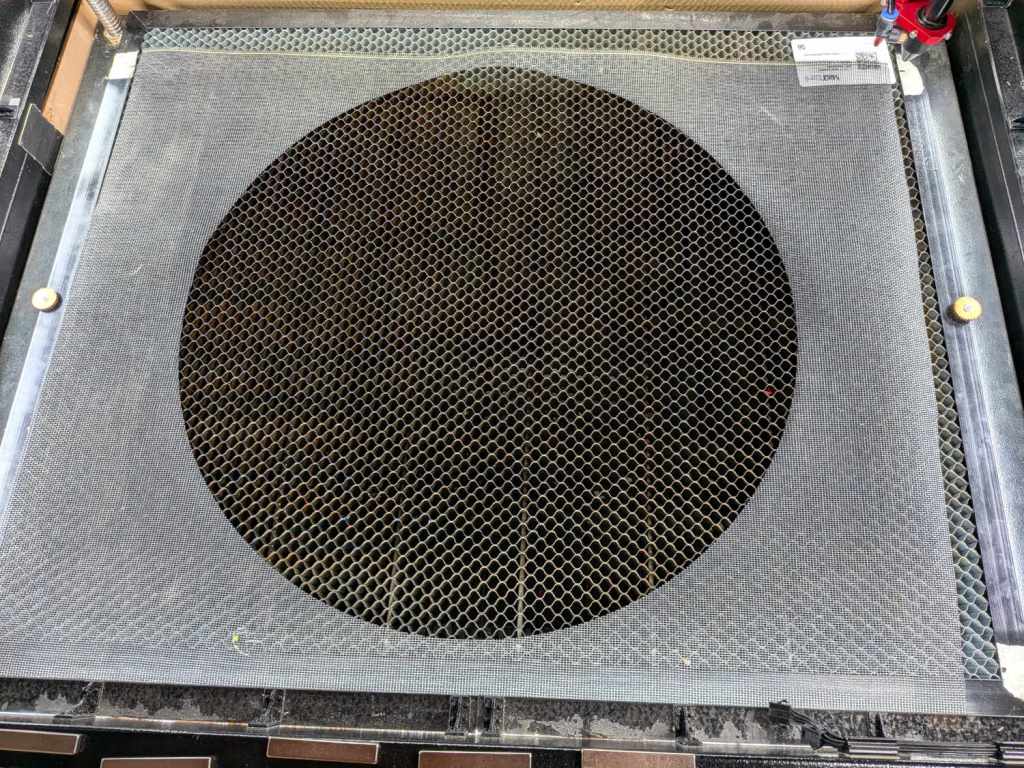
However, the circle lifted out with zero drama:

And was a perfect fit in the worm bin.
Color me surprised!
I have no pictures of the happy results, as all this happened in the few minutes between “We should try a screen”, dropping the cut screen in place, and reassembling the bin.
I think the screen would cut just as well with a higher speed. If the screen works and we need another, I’ll run a few tests first.