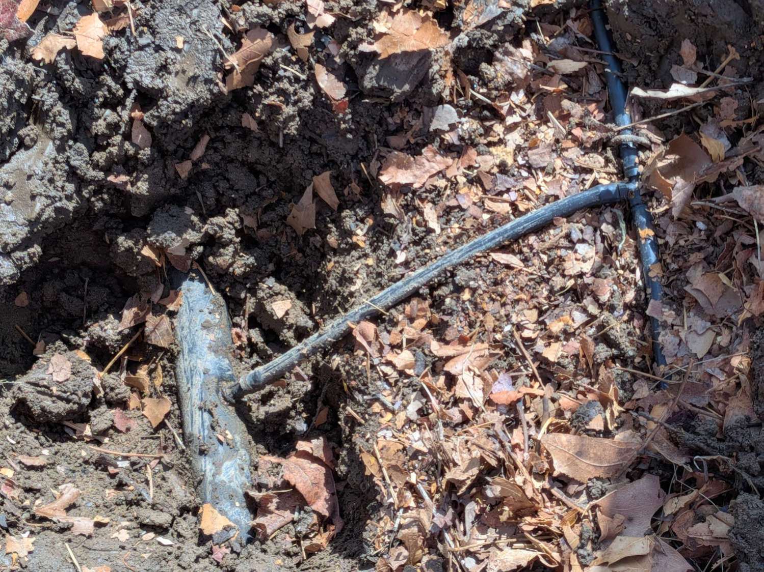
One of the zone valves on the gas furnace developed a slow leak around its actuator stem, so (now that the heating season is definitely over) I’ve been refurbishing all the long-neglected rubbery bits and pieces.
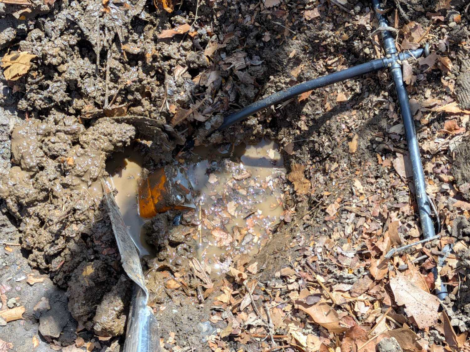
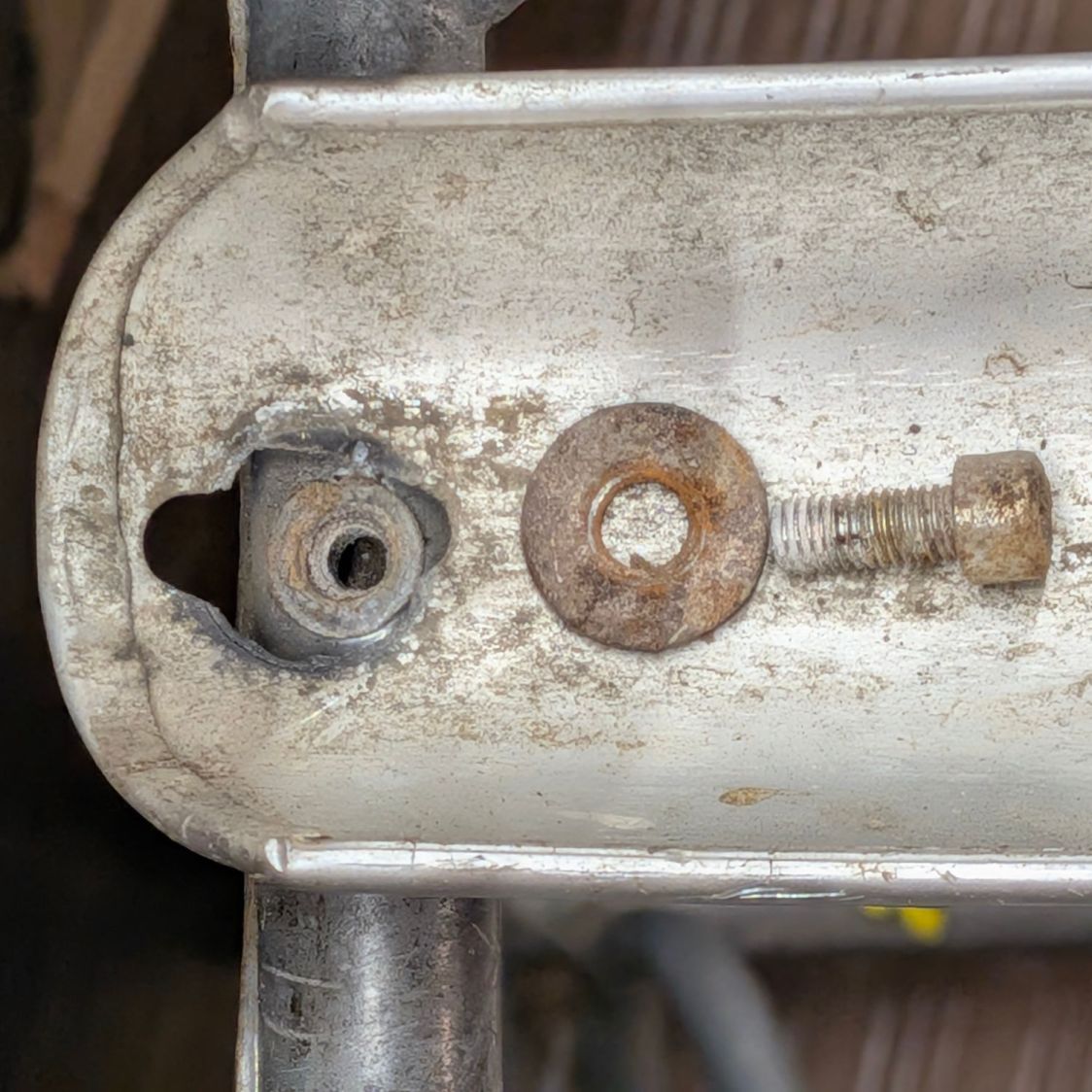
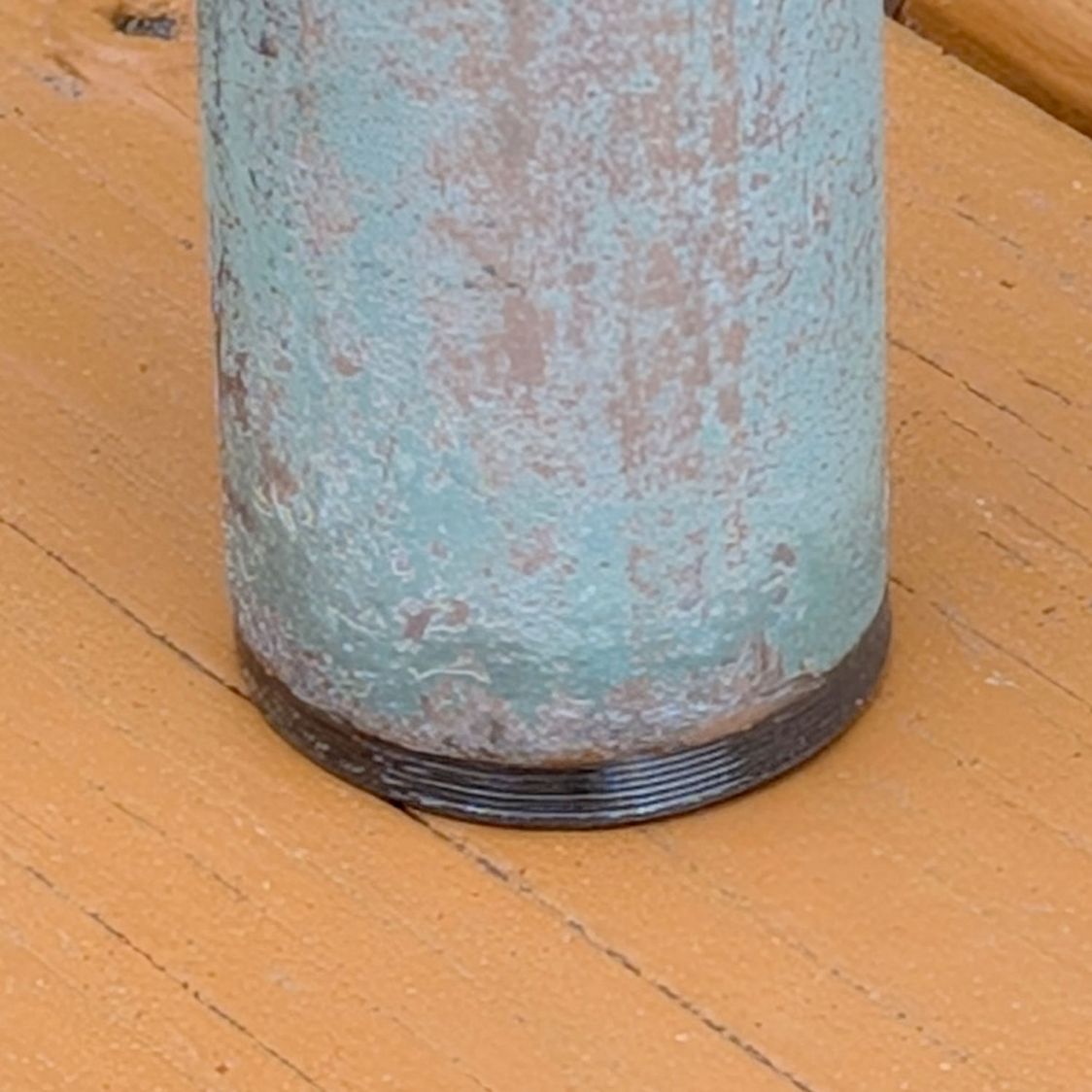
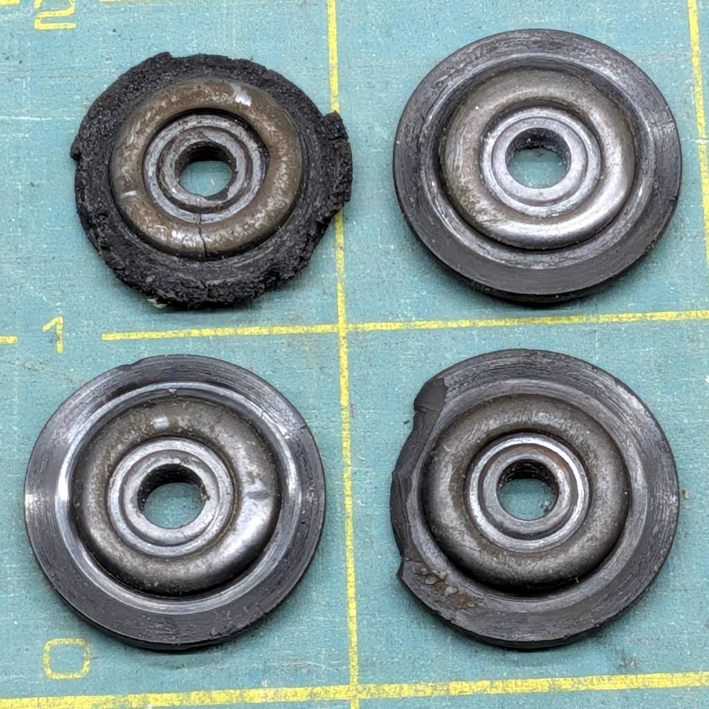
The four zone drain valves showed signs of having leaked in the past, so I took them apart to replace the washers:

As you’d expect, the two most-deteriorated washers were on the valves with the most corrosion.
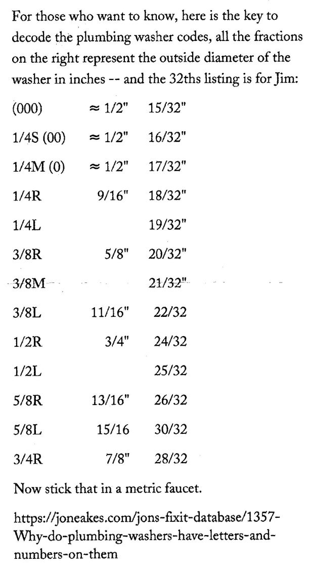
As I expected, the faucet washer assortment on the shelf didn’t have that size. Figuring the size based on the outside diameter produced a description of faucet washer size labels that confirmed my suspicion: it makes no sense whatsoever. In the event of link rot, a lightly reformatted version of his table:
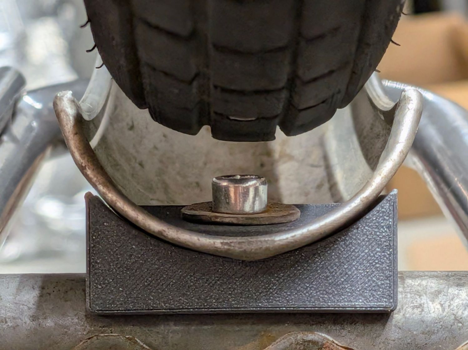
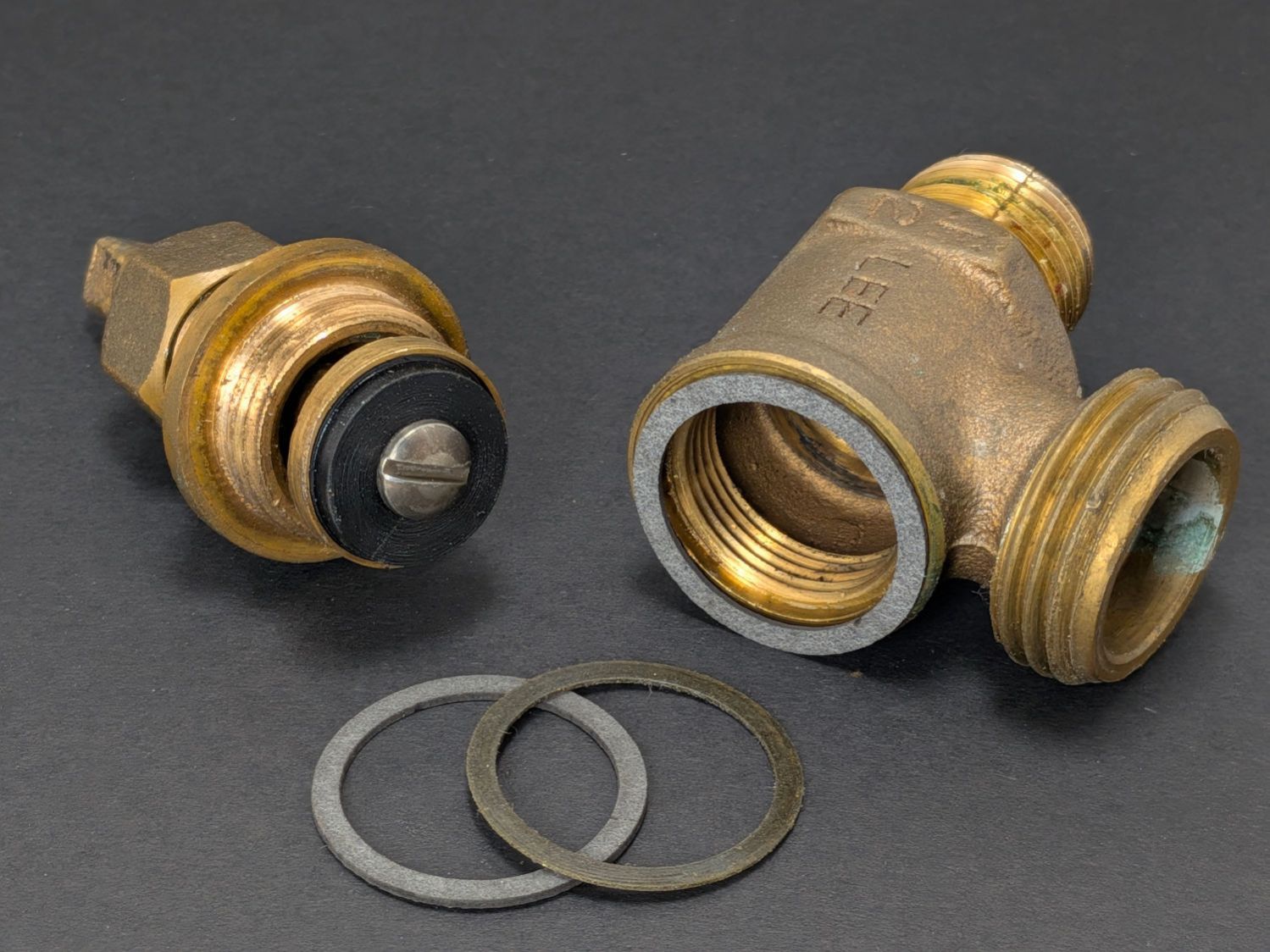
Careful measurement suggested they were 3/8L, which fit perfectly:
I added the spares and a copy of that table to the washer kit, although I’m certain the next project will involve a washer with yet another nonstandard standard size.
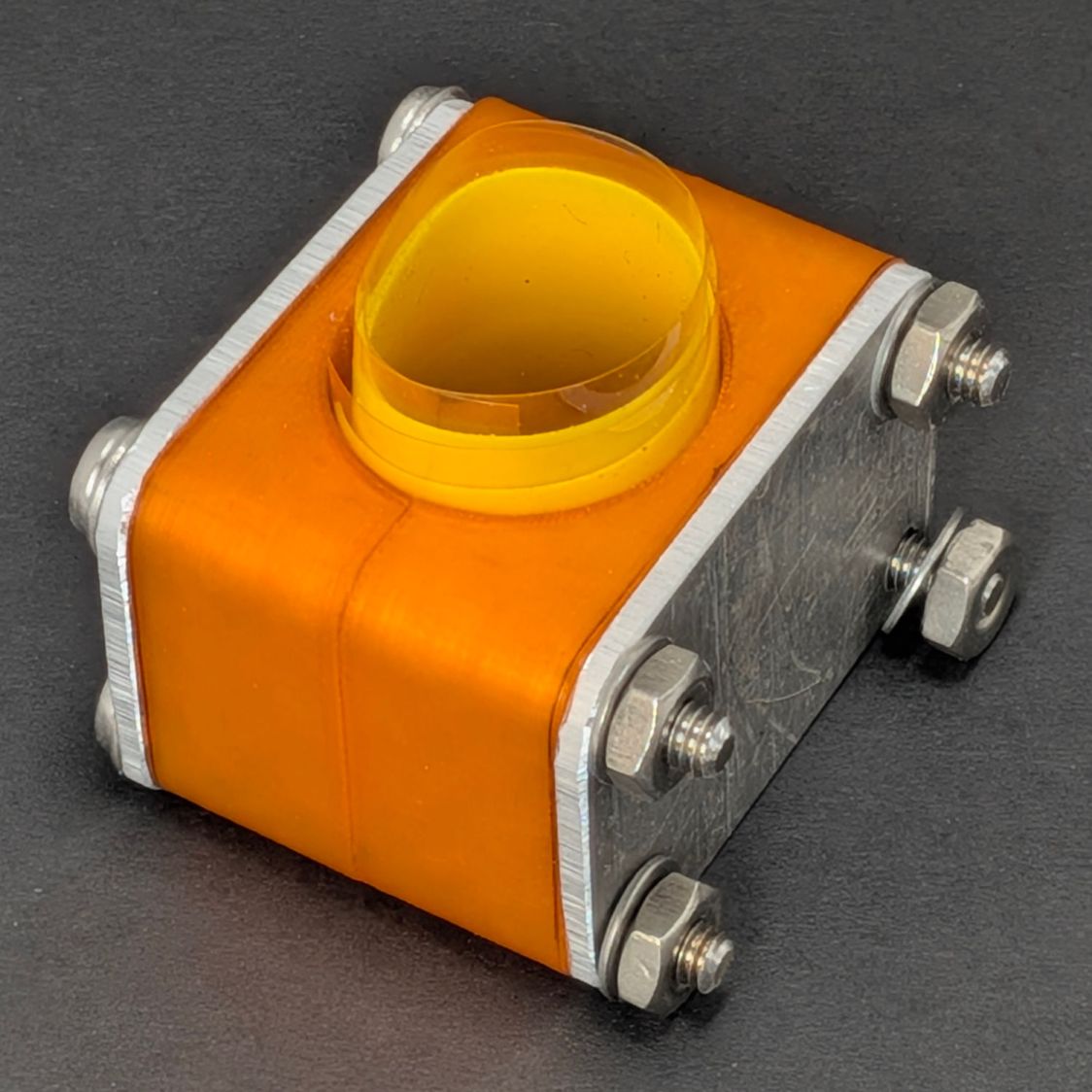
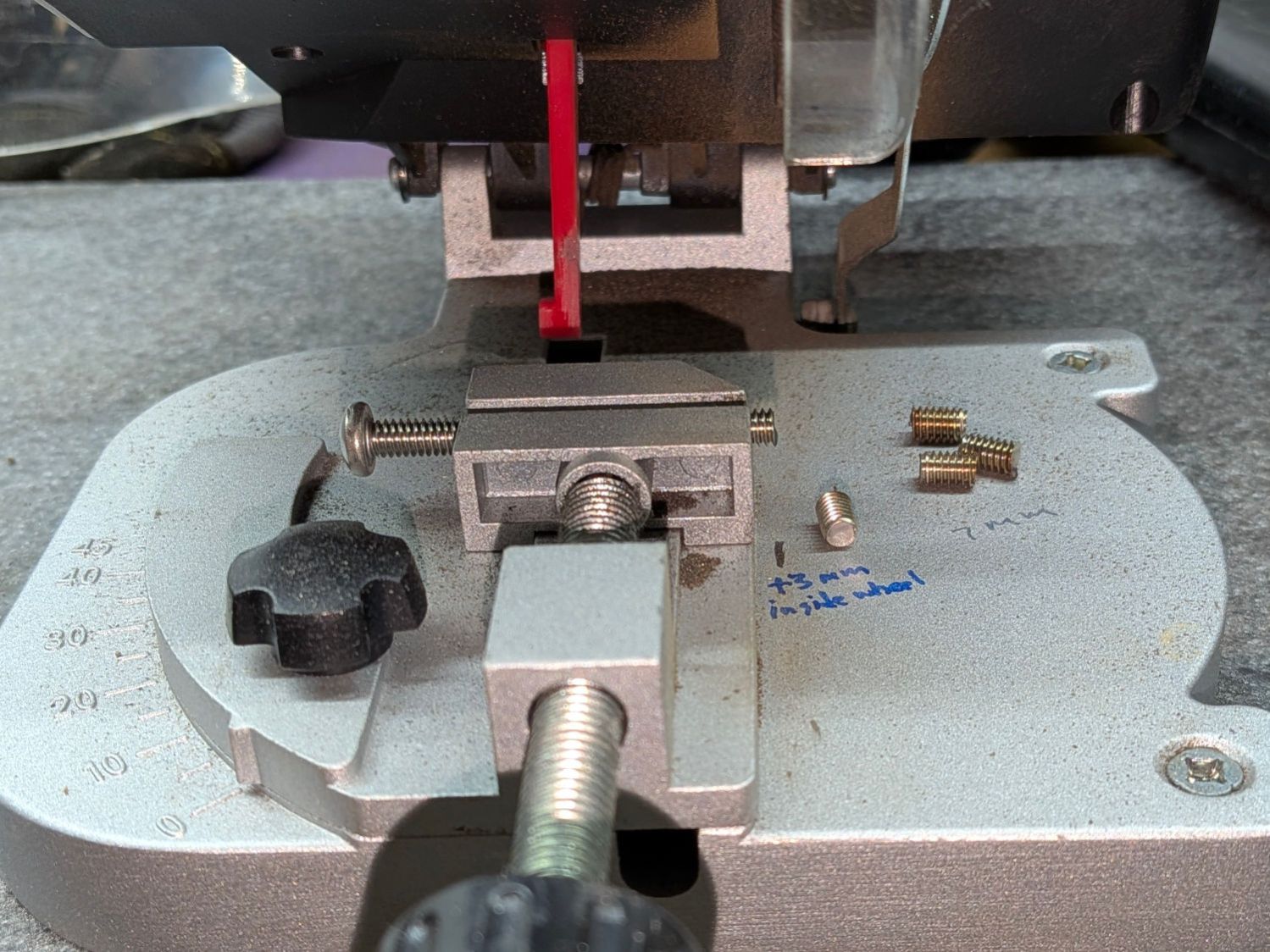
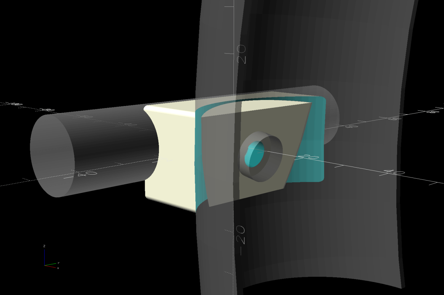
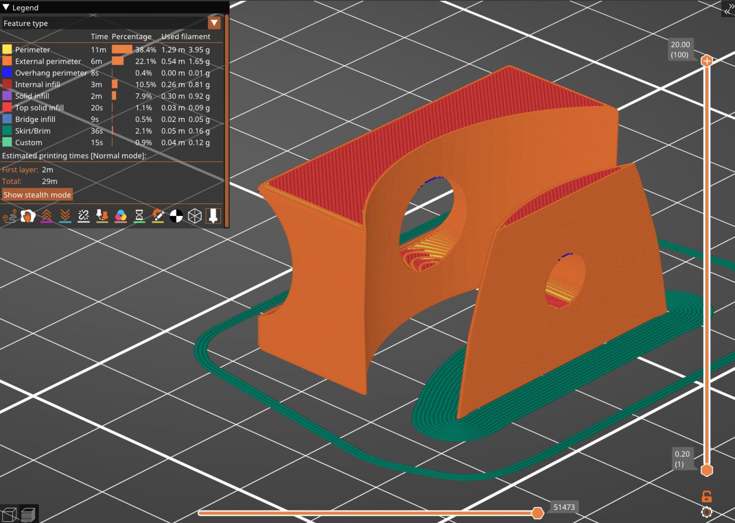
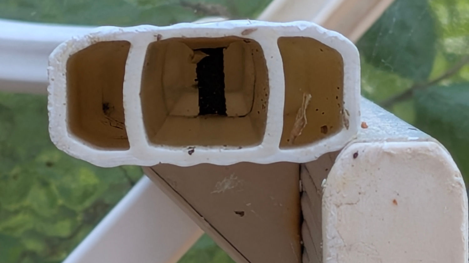
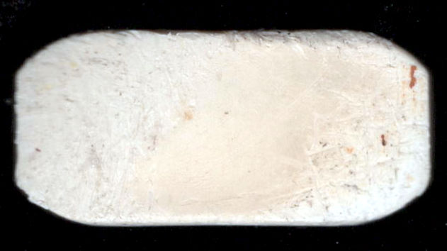
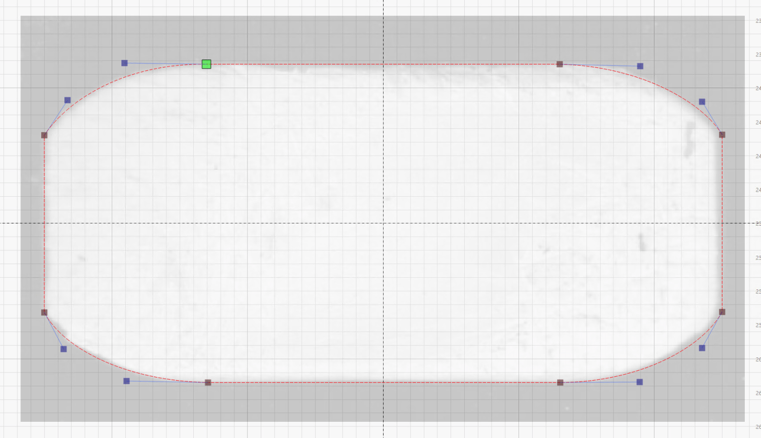
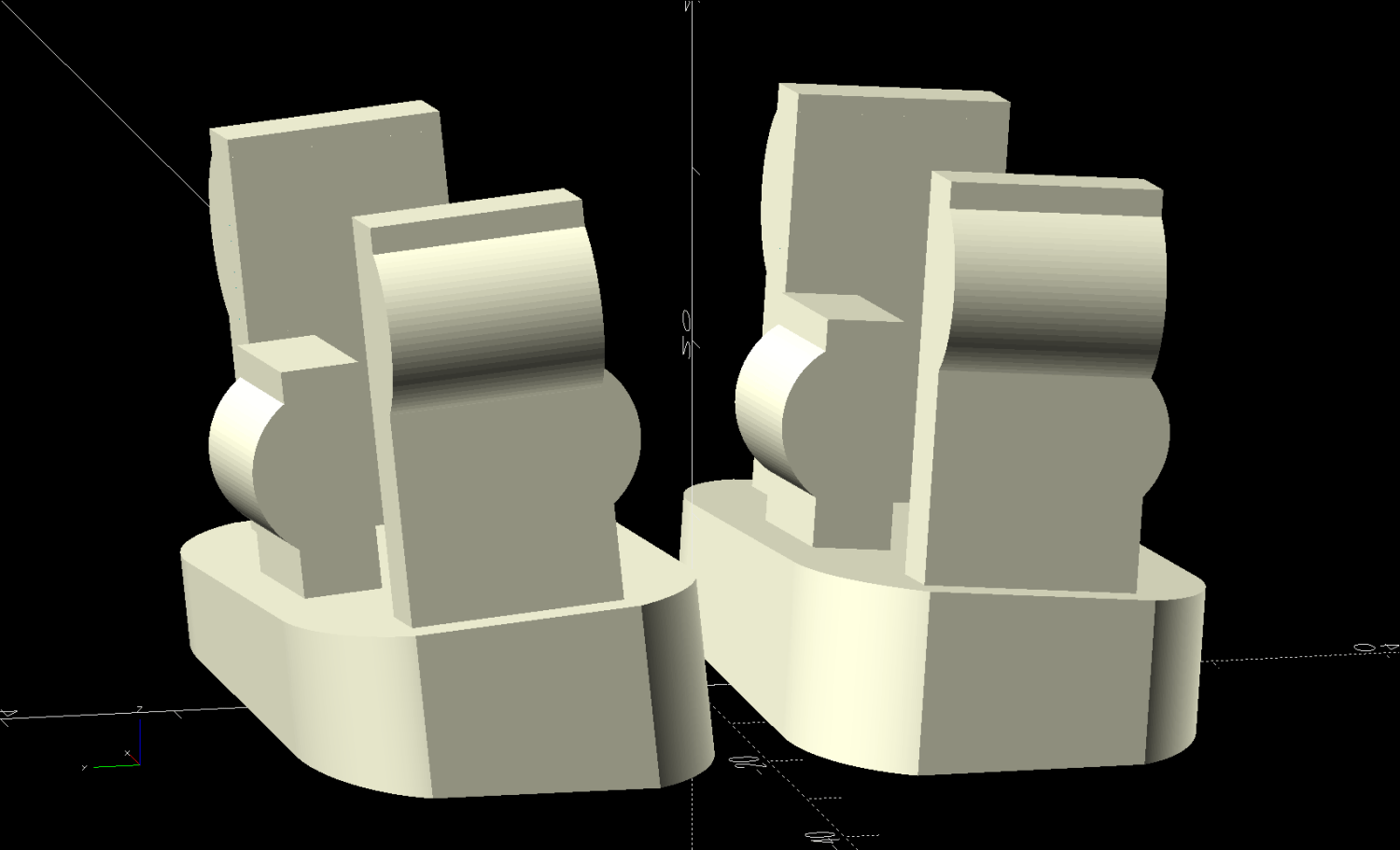
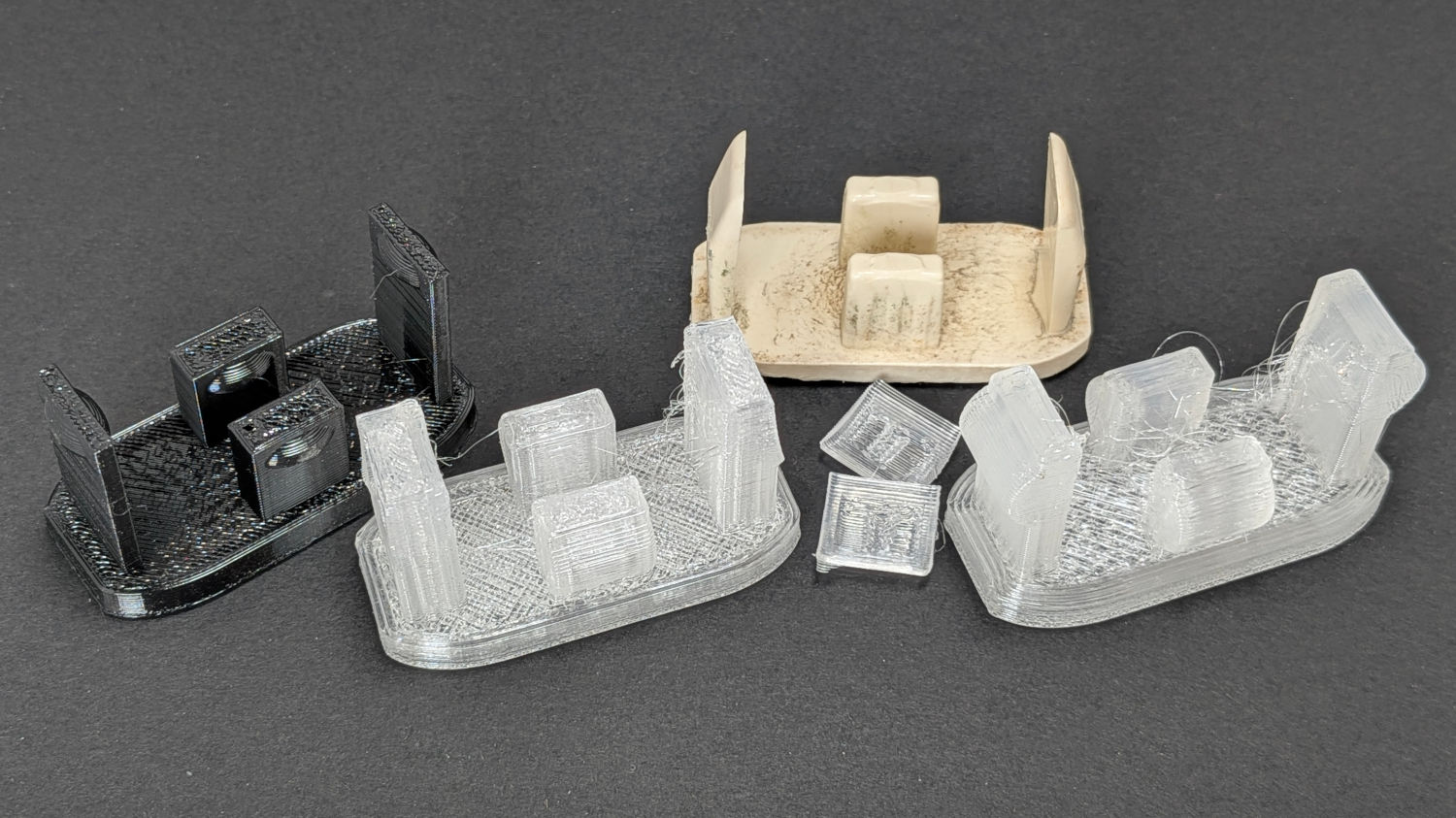
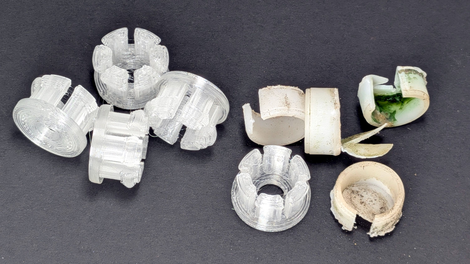
Replacing the washers required dismantling the valves and the first valve produced a gasket that fell out in brittle fragments. Although the remaining three gaskets emerged intact, I picked up some gasket material and laser-cut four new gaskets from the 0.8 mm sheet.
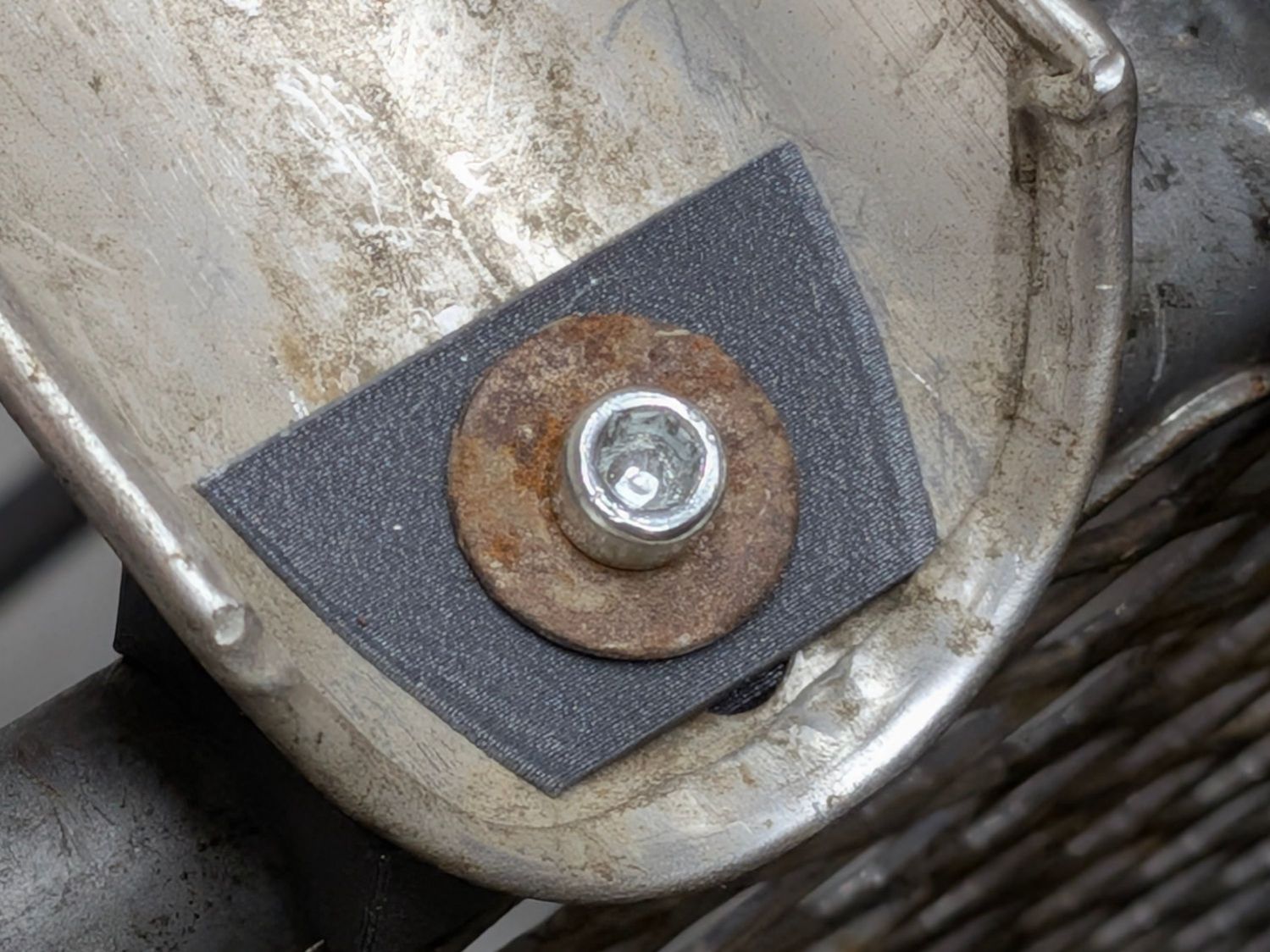
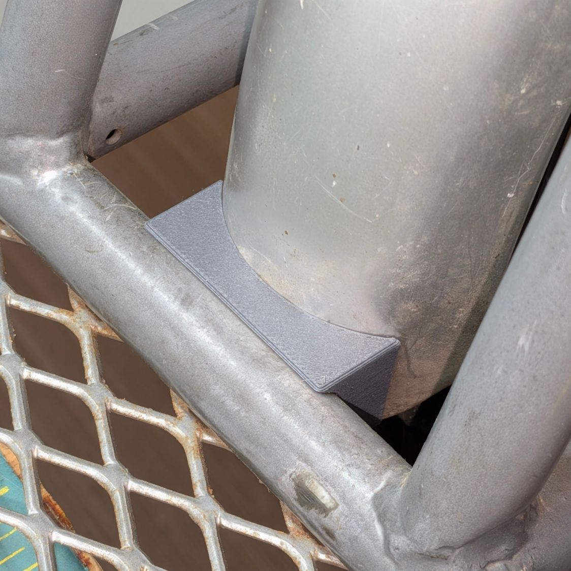
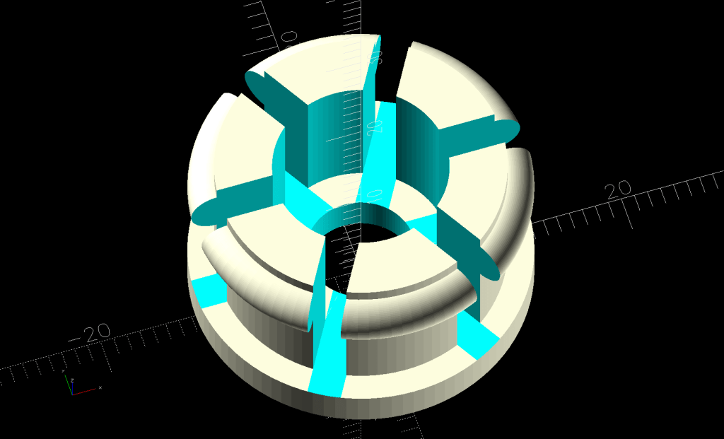
The OD fits into the valve body rebate:
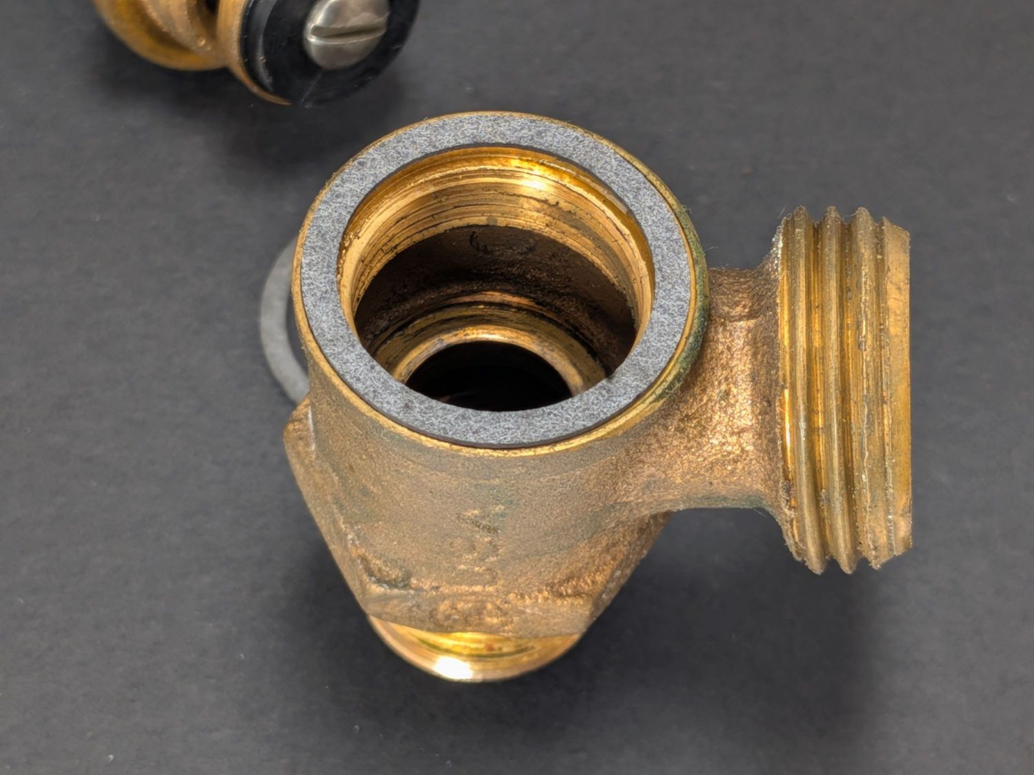
Because these valves are closed in operation and even when open won’t operate under any significant pressure, the gaskets aren’t particularly critical, but I dabbed joint compound into the body threads just to be sure.
And, while I was ordering things, I got a set of knobs to replace the sad bent wreckage on their stems.