Ed Nisley's Blog: Shop notes, electronics, firmware, machinery, 3D printing, laser cuttery, and curiosities. Contents: 100% human thinking, 0% AI slop.
Our new chest freezer has three baskets sliding along ridges just under the lid, but they seem to be just slightly too short for the ridge spacing. After having a basket fall off the rails once too often, I cut shims from 3 mm white acrylic and stuck them in place with double-sided foam tape to soak up the extra space:
Chest freezer basket shims
Each shim is 300×8 mm with the neatly rounded corners that are easy to do with a laser. They may not look like they grew there, but it’s tidy enough.
Perhaps the situation should have become a warranty claim, but a few minutes applying a tool to material I have on hand made the problem Go Away.
Which is entirely good enough for me and pretty much what I do around here most of the time anyway.
A new Gorilla Grip shower mat defeated the spring-loaded clip its predecessor dangled on between showers, so I applied a contour gauge to the shower stall, copied the shapes to paper, scanned them, then fit some curves:
Shower Mat Hanger – curve fitting
Combine the two to get a model of the shelf, subtract it from a rectangle, and produce a cardboard test piece:
Shower mat hanger – cardboard test 1
Put a hook on the bottom, a small bump on the top, and round the corners:
Shower Mat Hanger – LightBurn layout
Function-test a cardboard pair:
Shower mat hanger – cardboard test 2
They clear the hump along the edge and fit snugly across the front and sloping underside, so make an MVP from 6 mm acrylic:
Shower mat hanger – acrylic
Laser-cut acrylic may be too brittle for the job, but it gets the mat off the floor for drying and we’ll see how this works before doing anything more complex.
That’s not quite “as found”, because it came festooned with the remains of an obviously lab-built Peltier-cooled laser (?) diode fixture:
Rotary positioner – Peltier diode fixture
The positioner sported an obviously aftermarket tapped hole in the side, presumably for mounting to a support:
Rotary positioner – tapped mounting hole
The knob was apparently intended for fine angle adjustment, but it spun freely. Loosening another setscrew on the side released its well-worn parts:
Rotary positioner – drive gear – OEM knob
It’s not clear what the brown ring did, back when it did something, but there were no signs of stripped-off teeth or other debris in the recess; it is a very sloppy fit on the pin holding the knob. The knob may have had a compliant surface engaging the top of the ring, made with a long-since fossilized substance.
It turns out the rotary ring has triangles, not gear teeth:
Rotary positioner – tooth detail
However, setting the gear tooth pressure angle to 45° produces a reasonable triangle:
Rotary positioner – drive gear – solid model – end view
Even so, getting a functional knob required many iterations, primarily because I can’t measure any of the details and had to figure the fit by cut-and-try:
Rotary positioner – drive gear – gallery
The little white dots were an excuse to use the MMU3 for multi-material printing, because why not.
In truth, the knob doesn’t work particularly well, as the forces from the triangular teeth on the rotary ring tend to jam the knob against its pin. The knob might work better with splines driving a squishy TPU tire riding the crests of the rotary ring teeth than a real gear. Perhaps that’s what the original brown ring did before it fossilized.
For now, the positioner returns to the Box o’ Optics Lab Stuff, because it’s the wrong hammer for the Sherline’s laser aligner. It may emerge for a future project, when I’ll have more motivation to build a functional knob.
This file contains hidden or bidirectional Unicode text that may be interpreted or compiled differently than what appears below. To review, open the file in an editor that reveals hidden Unicode characters.
Learn more about bidirectional Unicode characters
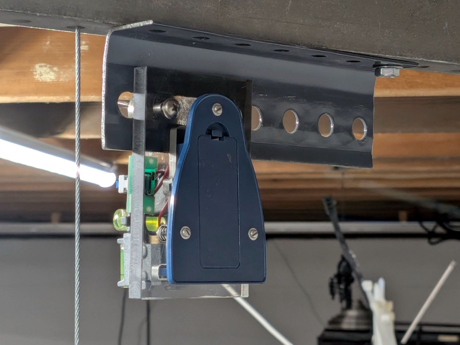
It’s (still) an upcycled laser line projector, minus the cylindrical lens stretching the dot into a line, running from a pair of AA alkaline cells:
Sherline laser aligner – rear view
The three small screws provide simpleminded angle adjustment, with the disadvantage of simultaneously moving the lens in the XY plane.
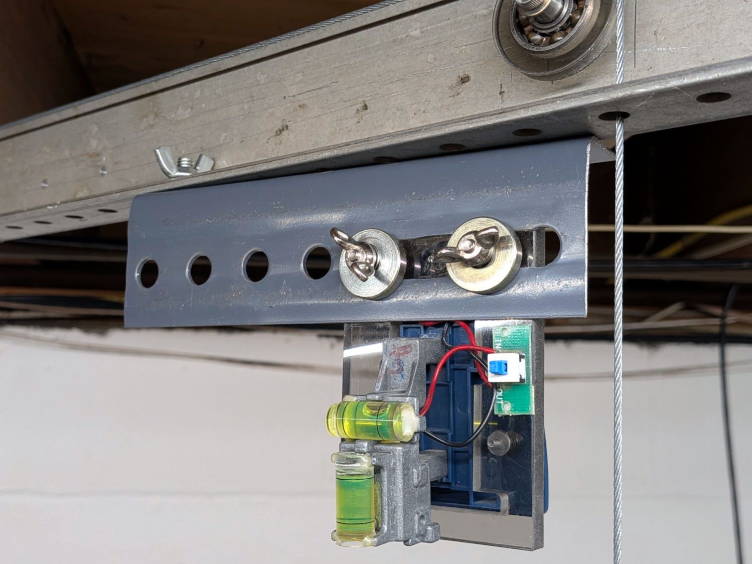
The upper bubble level shows it’s not at all vertical:
Sherline laser aligner – front view
That’s because the beam must fall down the middle of the Sherline’s spindle bore:
Sherline laser aligner – beam at spindle top
Getting the alignment right requires a mirror on the tooling plate, which I will not attempt to photograph again, reflecting the beam upward through the spindle, where it will light up the bottom of the no-longer-a-line projector’s lens mount. When that happens, the projector is boresighted on the spindle, regardless of whether the tooling plate is perpendicular to the local gravitational field.
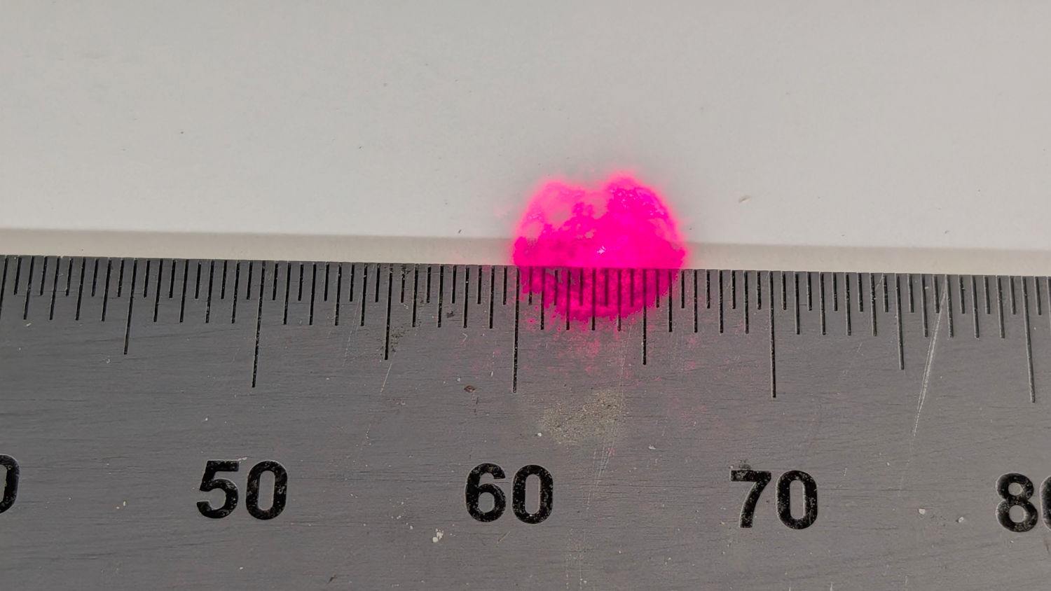
With the Z axis / spindle near the top of its travel, screwing the lens (mounted in a toolholder) onto the spindle produces a defocused beam on the tooling plate:
Sherline laser aligner – defocused spot – on scale
If the spot doesn’t look similarly round-ish, then the beam isn’t completely filling the entrance pupil of the lens and you must twiddle the projector’s angle / position until it does.
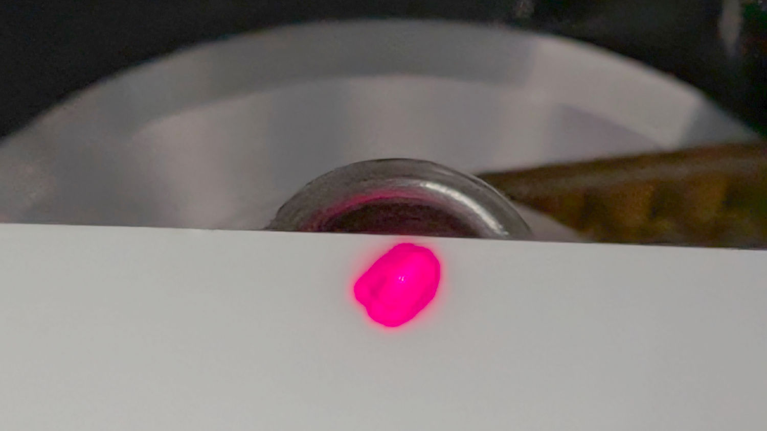
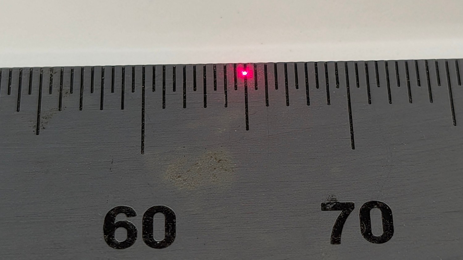
With that done, running the Z axis to put the lens about 30 mm above the plate produces a suitably teeny spot:
Sherline laser aligner – focused spot on scale
The Sherline’s previous home atop that same gray countertop had been firmly affixed to the basement wall, with the gantry and laser projector screwed to the floor joists: everything immovable. The countertop now sits atop a workbench not firmly affixed to anything: a good solid bump will likely knock the Sherline out of alignment with the beam.
How often that happens and how awful recovery will be remains to be seen. For now, It Just Works™ again.
Feeding Sherline aligner into the search box will reveal much of the backstory.
I extracted an XZ positioner from the Box o’ Optics Lab Stuff before coming to my senses: this is not nearly such a critical application.
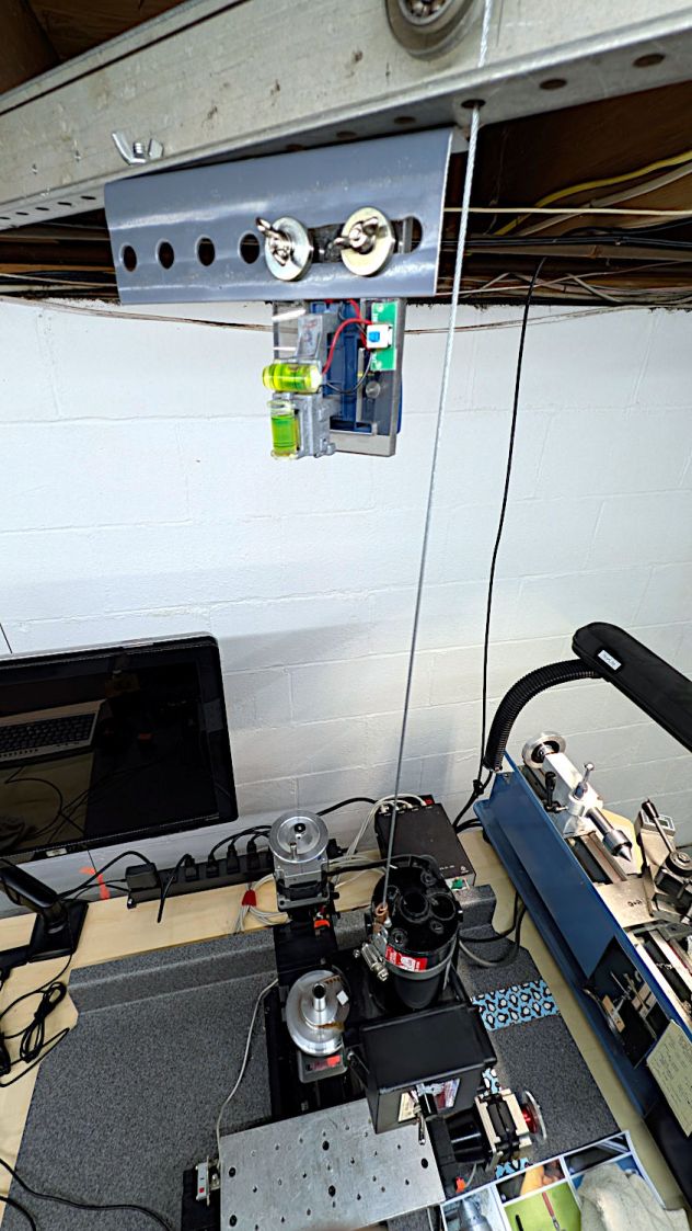
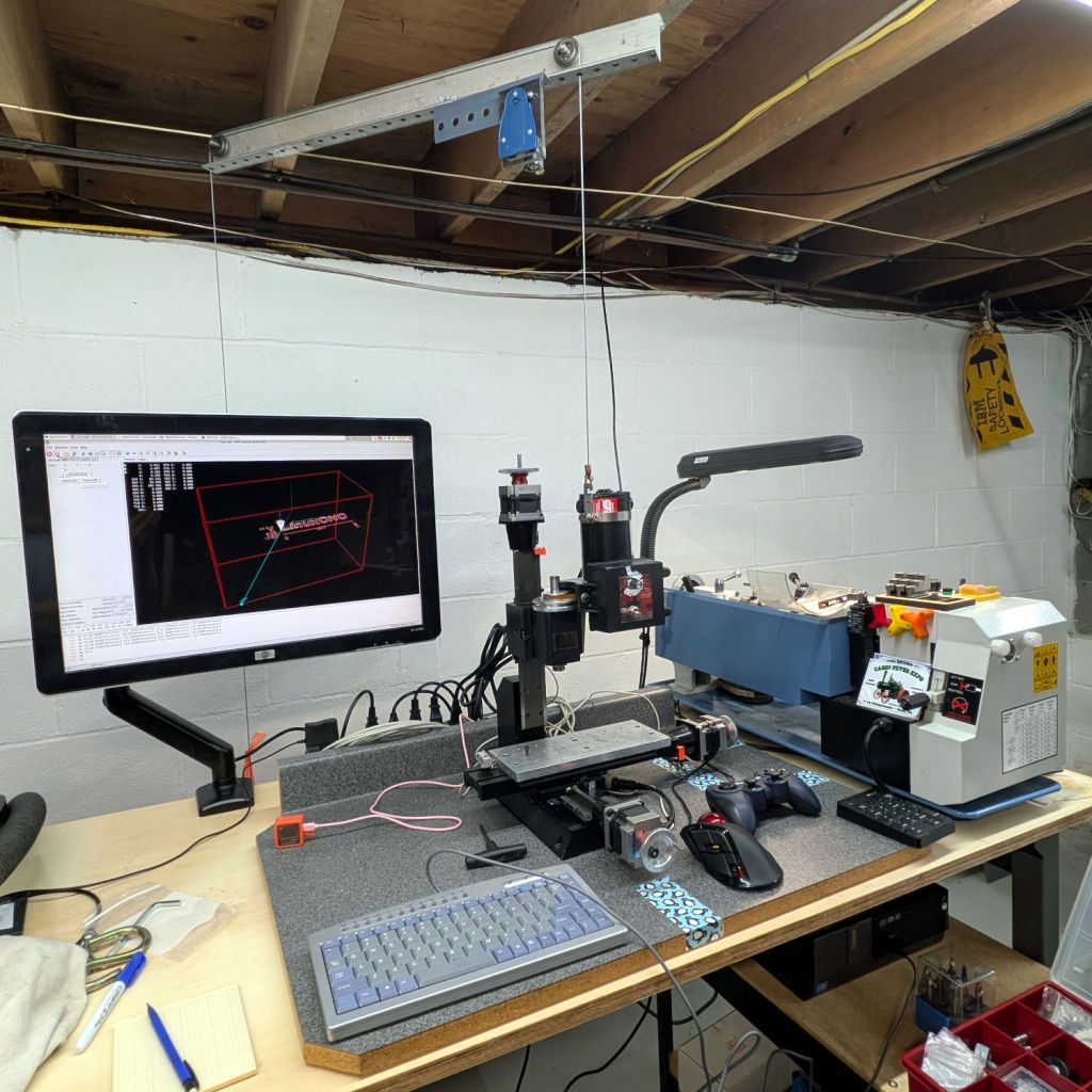
Notes on finally getting the Sherline CNC mill operating in its new home, with a suitable Axis startup image:
Sherline setup 2026-06
The gray countertop from its former home sits on foam strips soaking up a slight warp with enough isolation to keep things quiet.
The gantry required the usual fiddling to make the cable hoist the Z axis directly upward, with the orange flag on the counterweight barely visible below the monitor.
A clean installation of LinuxCNC 2.9.8 on an ancient Dell Optiplex 9020 proceeded smoothly. Installing x11vnc let the rest of the proceedings happen from upstairs in the Comfy Chair. For unknown reasons, vinagre works better than Reminna as a VNC client, after recalling F11 enters / exits fullscreen mode.
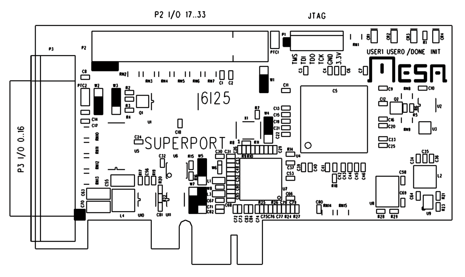
The mesaflash utility accompanying LinuxCNC 2.9.8 did not recognize the Mesa 6i25 card. Fetching & compiling the most recent version (3.5.17) cleared that hump and flashed the bitmap:
The 6i25 wants to be known as a 5i25, with its jumpers in their default positions:
Mesa 6i25 – jumper locations
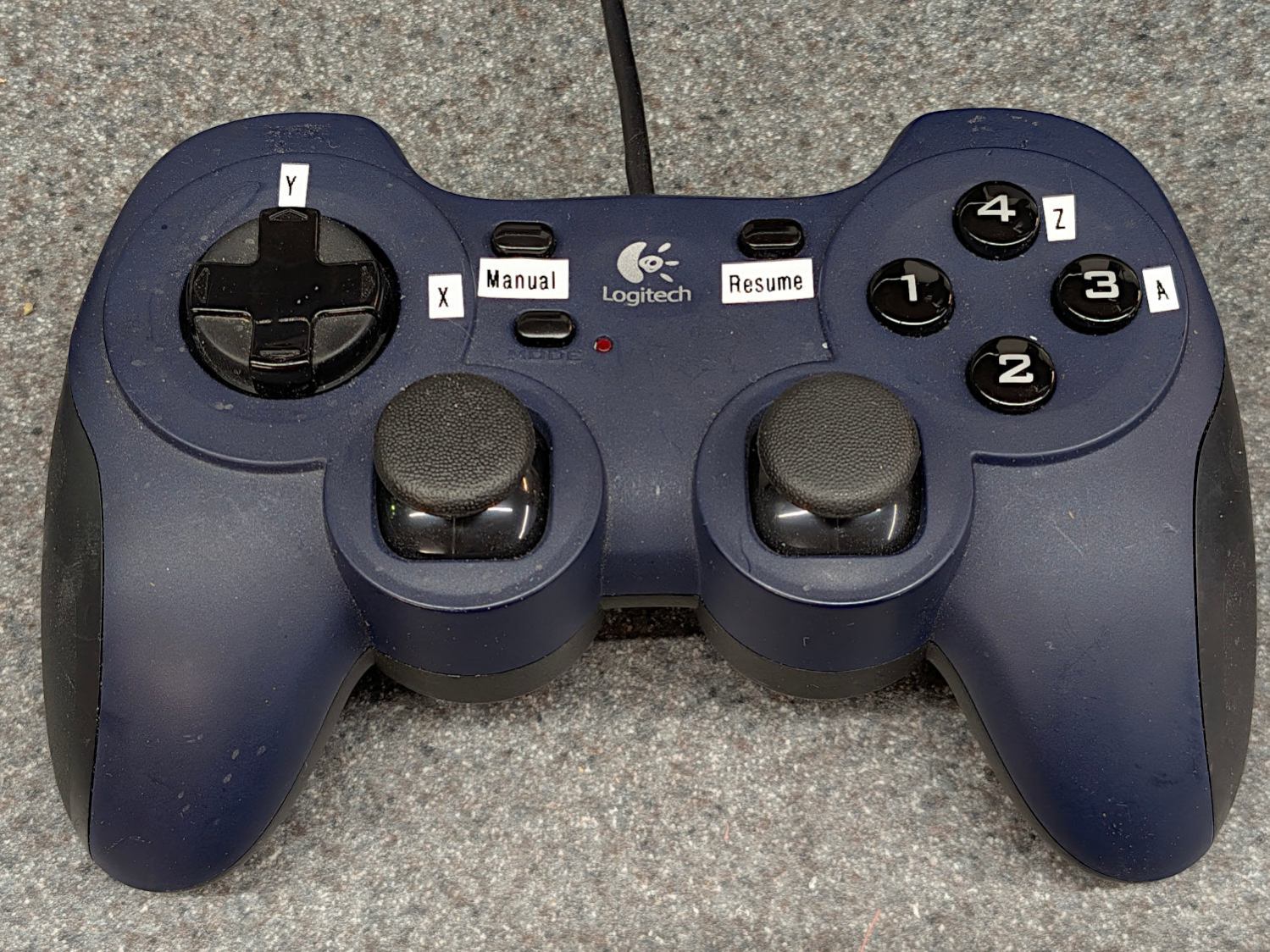
For unknown reasons, the button originally known as btn-triggerbecame btn-joystick for a while and has now reverted to btn-trigger. It’s labeled 1 in the four-button cluster:
Logitech Dual-Action Gamepad – relabeled
Which required changing the pin name in the Kicad library component:
Sherline HAL schematic – Logitech button 1 name
Which required converting the old Kicad library format into the new Kicad library format, a completely automatic process without, AFAICT, any unpleasant side effects.
The new name fed into the schematic as expected, after minor fumbling while re-adding the modified component and setting its annotation number:
Sherline HAL schematic – Logitech AZ button logic
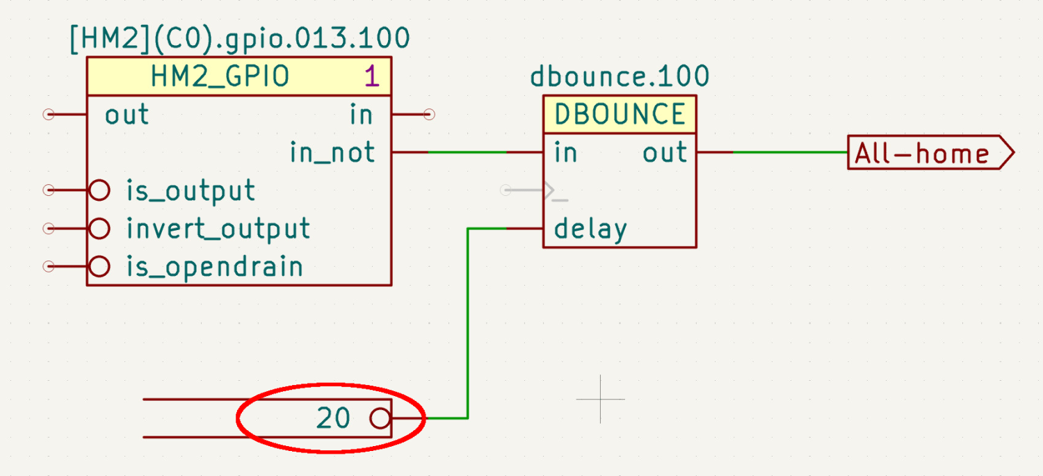
The X axis home microswitch has (apparently) become more bouncy while it was idle, so I increased the number of samples before HAL sees a change in that GPIO input:
Sherline HAL schematic – home switch debounce
The dbounce block runs in the servo thread at 1 m per tick, so those 20 samples take all of 20 ms while the X axis moves 0.15 mm. At some point I should apply a scope to that switch, but for now It Just Works™.
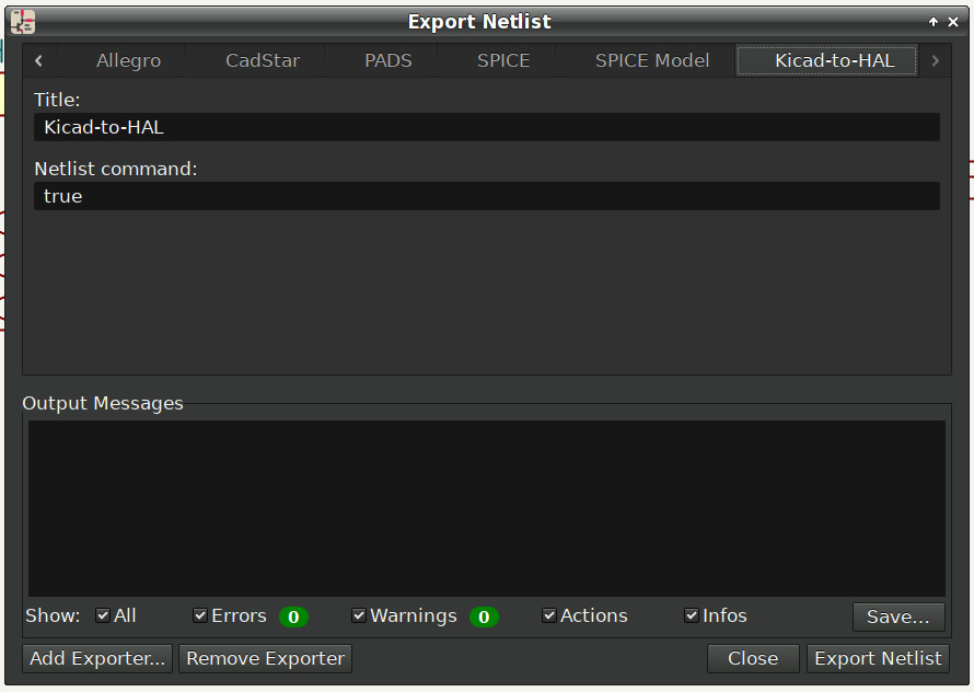
Kicad produces an “intermediate XML file” containing the netlist data intended for a conversion / export program, which is basically what my Kicad-to-HAL lashup does. I told Kicad to use Bash’s true command as a converter:
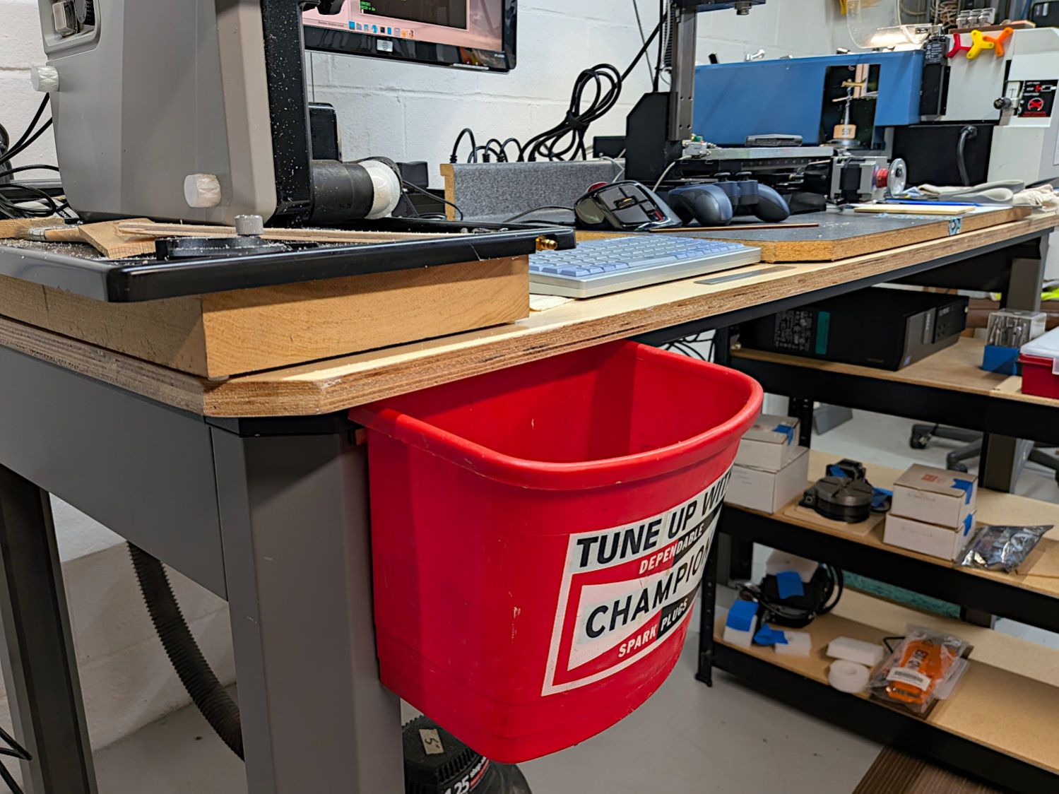
You don’t have one of these, but your bench needs something like it:
Workbench scrap can
Tiny Bandsaw perches just above it and now I have a place to drop the scraps you see collecting in its tray.
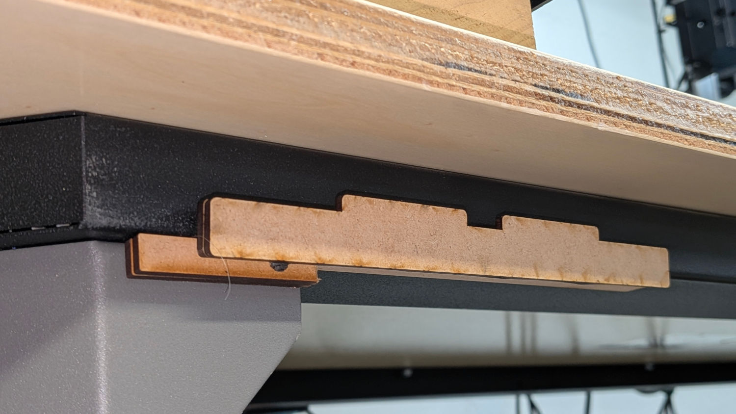
The can hangs by its rim from a completely kludged two-layered MDF hook stuck to the metal table frame with good 3M foam tape:
Workbench scrap can hanger
It’s not in the way of Tiny Bandsaw, because I stand at the left end of the bench, and it’s not in the way of the Sherline / LinuxCNC keyboard, because I stand to its right. So far, so good.
Should it fall off, I’ll think of something better.
All the parts arrived jammed into the clear box where I had trouble figuring out the collet sizes.
A few minutes with LightBurn and a scrap of 6 mm white acrylic produced a collet holder / organizer:
Dremel collet holder – detail
Seen in the cold light of day, the upper 1.8 and 2.0 mm collets look swapped, which pretty much demonstrates the need for the holder.
The nice engraved letters come from scribbling a chisel-tip black marker before peeling the protective paper off the acrylic. The black lacquer crayon I intended to use must be in a different box than the markers, but the results suffice for the intended purpose.