Ed Nisley's Blog: Shop notes, electronics, firmware, machinery, 3D printing, laser cuttery, and curiosities. Contents: 100% human thinking, 0% AI slop.
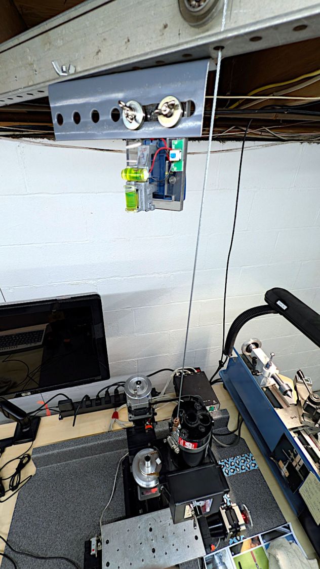
It’s (still) an upcycled laser line projector, minus the cylindrical lens stretching the dot into a line, running from a pair of AA alkaline cells:
Sherline laser aligner – rear view
The three small screws provide simpleminded angle adjustment, with the disadvantage of simultaneously moving the lens in the XY plane.
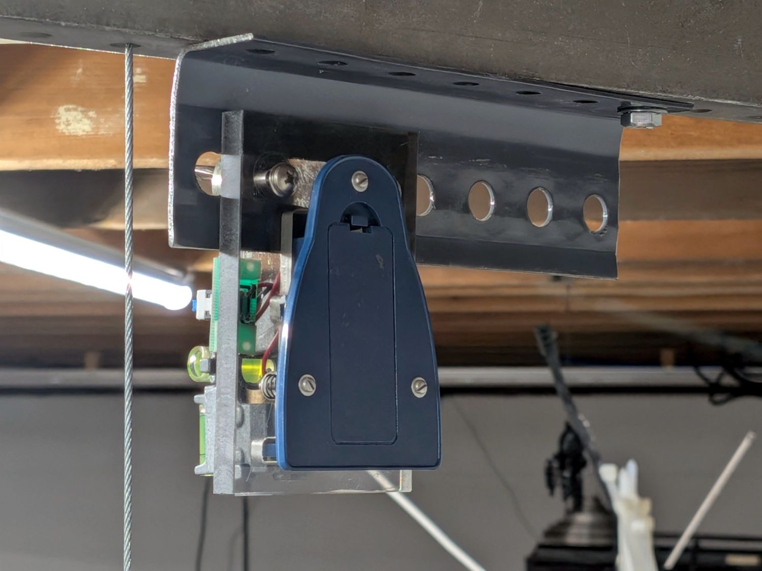
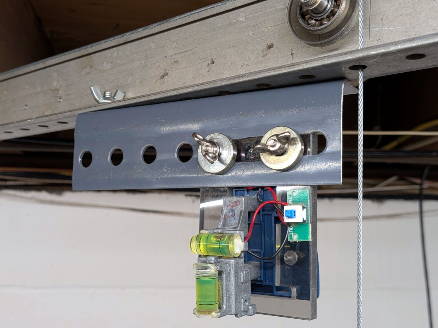
The upper bubble level shows it’s not at all vertical:
Sherline laser aligner – front view
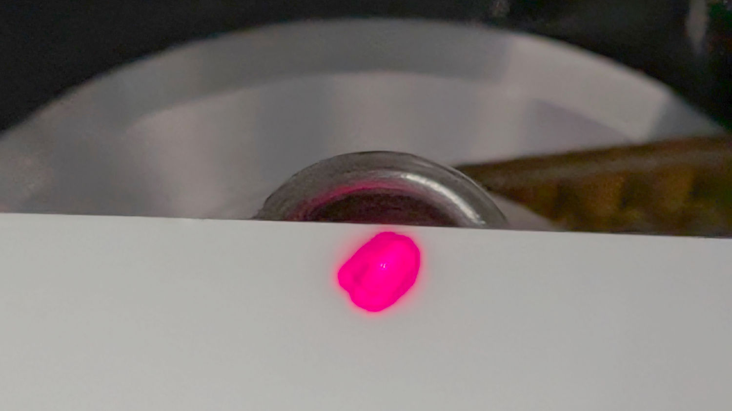
That’s because the beam must fall down the middle of the Sherline’s spindle bore:
Sherline laser aligner – beam at spindle top
Getting the alignment right requires a mirror on the tooling plate, which I will not attempt to photograph again, reflecting the beam upward through the spindle, where it will light up the bottom of the no-longer-a-line projector’s lens mount. When that happens, the projector is boresighted on the spindle, regardless of whether the tooling plate is perpendicular to the local gravitational field.
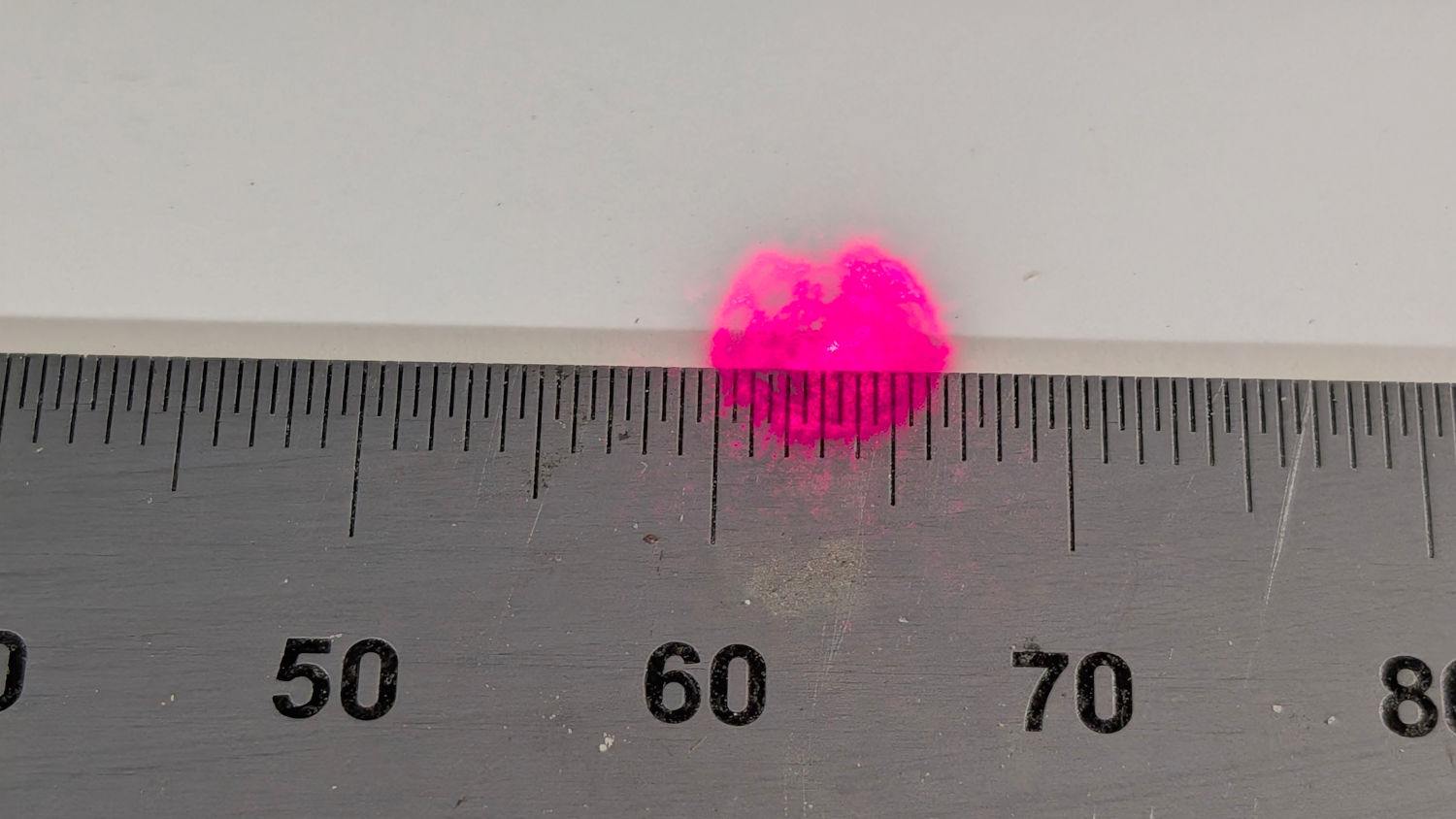
With the Z axis / spindle near the top of its travel, screwing the lens (mounted in a toolholder) onto the spindle produces a defocused beam on the tooling plate:
Sherline laser aligner – defocused spot – on scale
If the spot doesn’t look similarly round-ish, then the beam isn’t completely filling the entrance pupil of the lens and you must twiddle the projector’s angle / position until it does.
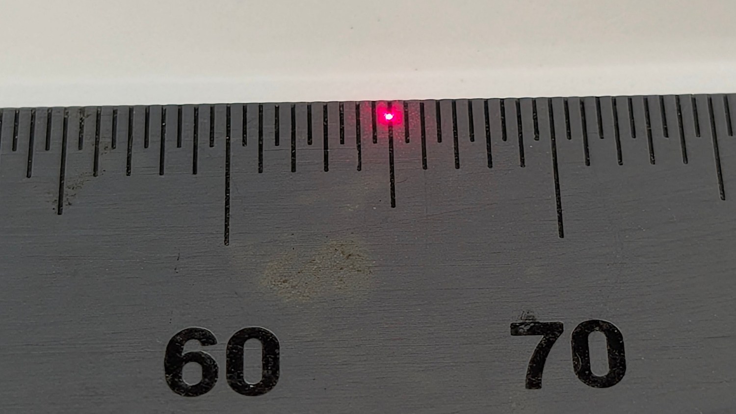
With that done, running the Z axis to put the lens about 30 mm above the plate produces a suitably teeny spot:
Sherline laser aligner – focused spot on scale
The Sherline’s previous home atop that same gray countertop had been firmly affixed to the basement wall, with the gantry and laser projector screwed to the floor joists: everything immovable. The countertop now sits atop a workbench not firmly affixed to anything: a good solid bump will likely knock the Sherline out of alignment with the beam.
How often that happens and how awful recovery will be remains to be seen. For now, It Just Works™ again.
Feeding Sherline aligner into the search box will reveal much of the backstory.
I extracted an XZ positioner from the Box o’ Optics Lab Stuff before coming to my senses: this is not nearly such a critical application.
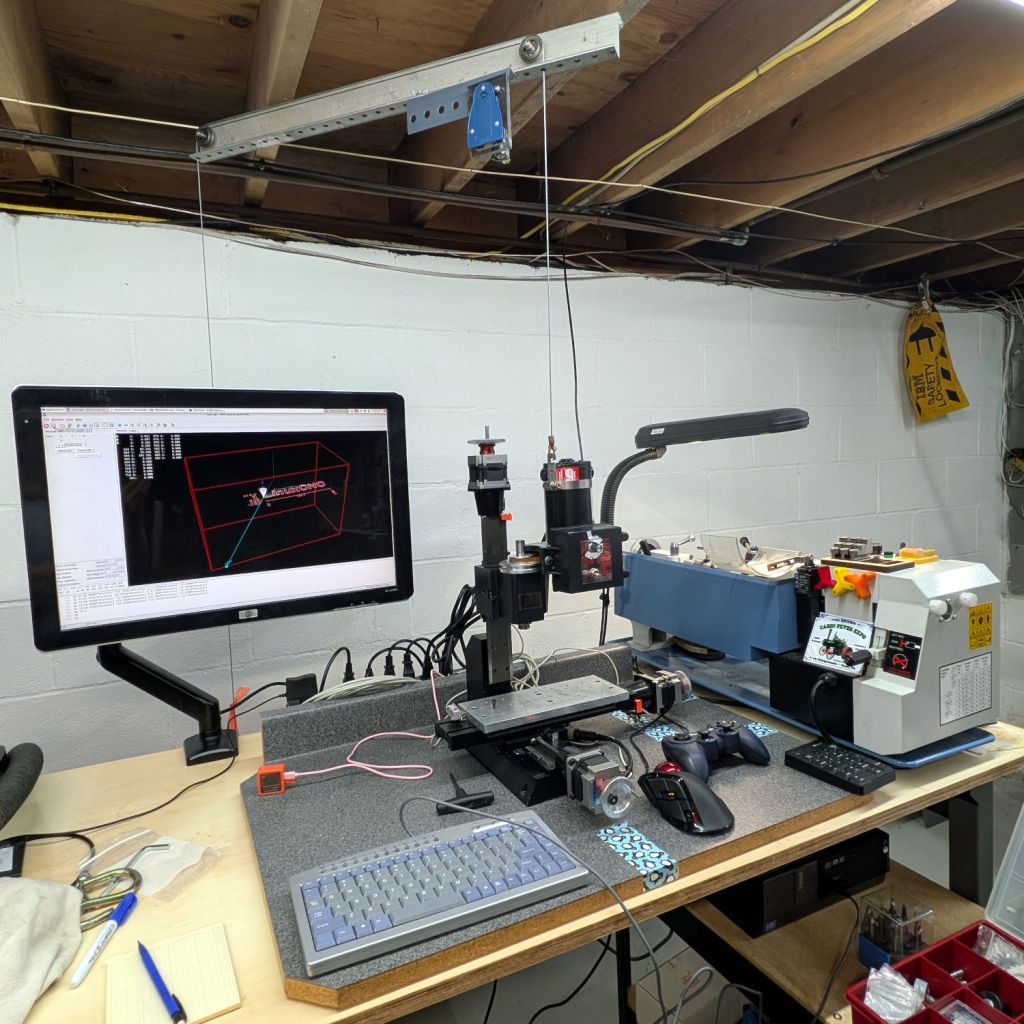
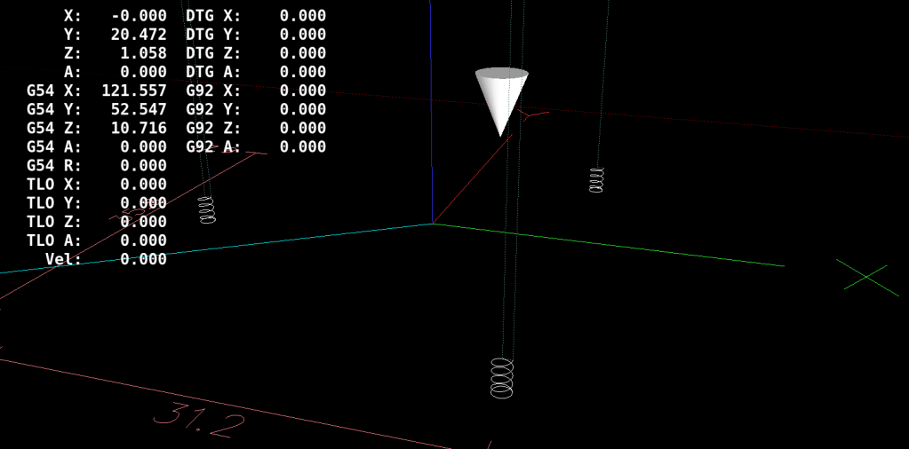
Notes on finally getting the Sherline CNC mill operating in its new home, with a suitable Axis startup image:
Sherline setup 2026-06
The gray countertop from its former home sits on foam strips soaking up a slight warp with enough isolation to keep things quiet.
The gantry required the usual fiddling to make the cable hoist the Z axis directly upward, with the orange flag on the counterweight barely visible below the monitor.
A clean installation of LinuxCNC 2.9.8 on an ancient Dell Optiplex 9020 proceeded smoothly. Installing x11vnc let the rest of the proceedings happen from upstairs in the Comfy Chair. For unknown reasons, vinagre works better than Reminna as a VNC client, after recalling F11 enters / exits fullscreen mode.
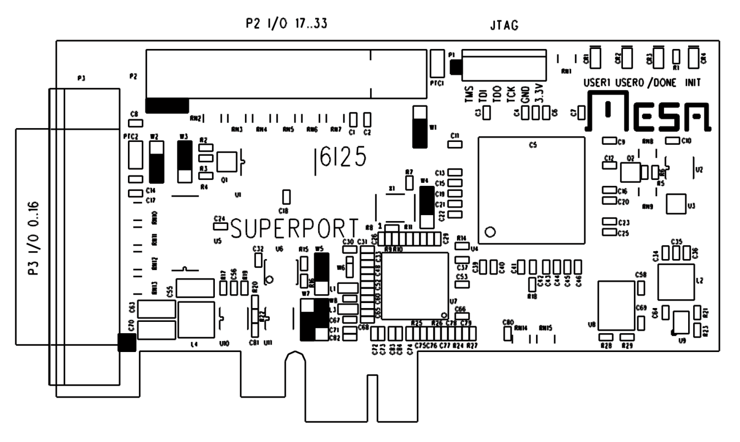
The mesaflash utility accompanying LinuxCNC 2.9.8 did not recognize the Mesa 6i25 card. Fetching & compiling the most recent version (3.5.17) cleared that hump and flashed the bitmap:
The 6i25 wants to be known as a 5i25, with its jumpers in their default positions:
Mesa 6i25 – jumper locations
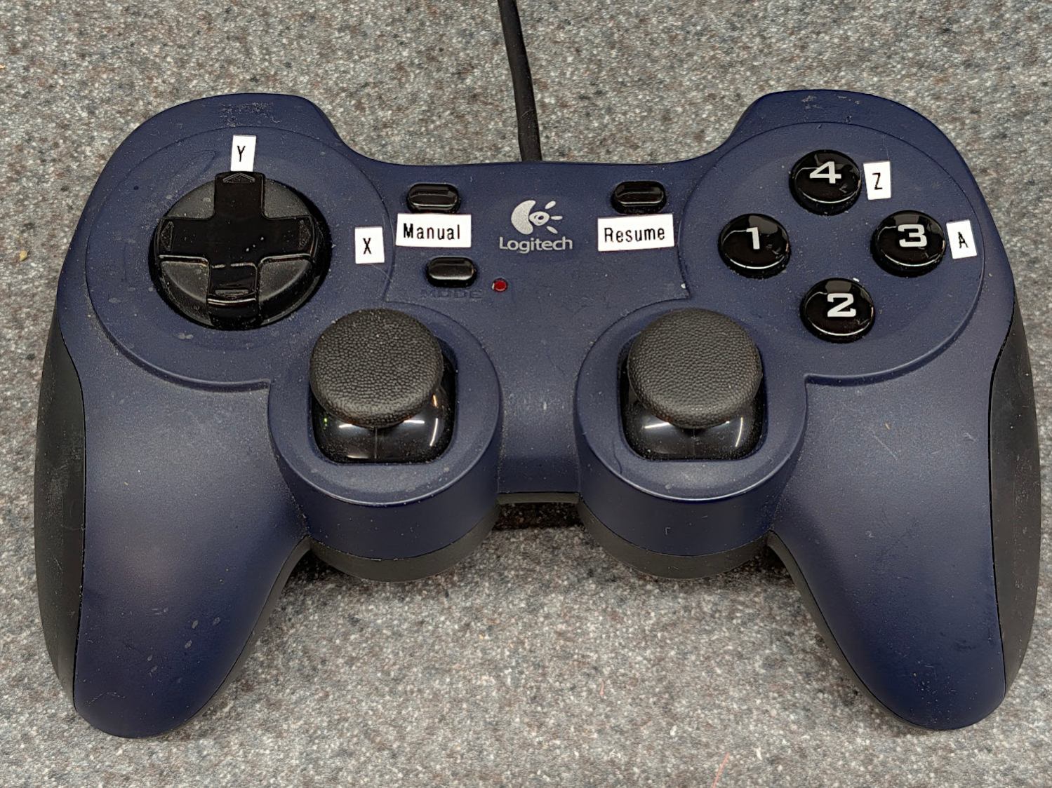
For unknown reasons, the button originally known as btn-triggerbecame btn-joystick for a while and has now reverted to btn-trigger. It’s labeled 1 in the four-button cluster:
Logitech Dual-Action Gamepad – relabeled
Which required changing the pin name in the Kicad library component:
Sherline HAL schematic – Logitech button 1 name
Which required converting the old Kicad library format into the new Kicad library format, a completely automatic process without, AFAICT, any unpleasant side effects.
The new name fed into the schematic as expected, after minor fumbling while re-adding the modified component and setting its annotation number:
Sherline HAL schematic – Logitech AZ button logic
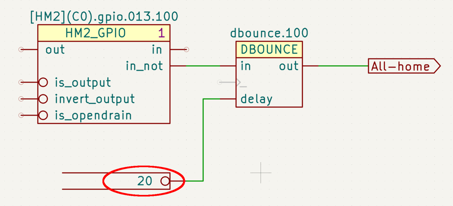
The X axis home microswitch has (apparently) become more bouncy while it was idle, so I increased the number of samples before HAL sees a change in that GPIO input:
Sherline HAL schematic – home switch debounce
The dbounce block runs in the servo thread at 1 m per tick, so those 20 samples take all of 20 ms while the X axis moves 0.15 mm. At some point I should apply a scope to that switch, but for now It Just Works™.
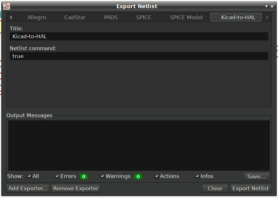
Kicad produces an “intermediate XML file” containing the netlist data intended for a conversion / export program, which is basically what my Kicad-to-HAL lashup does. I told Kicad to use Bash’s true command as a converter:
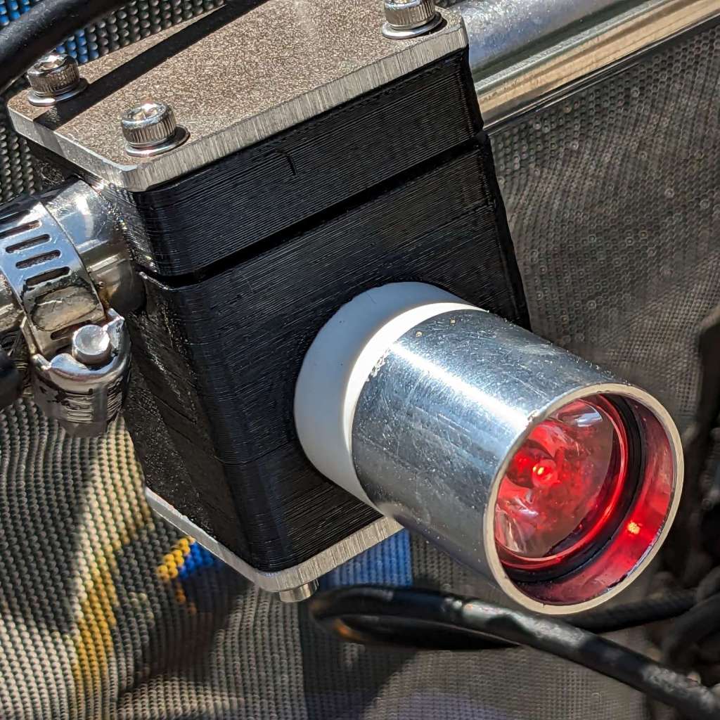
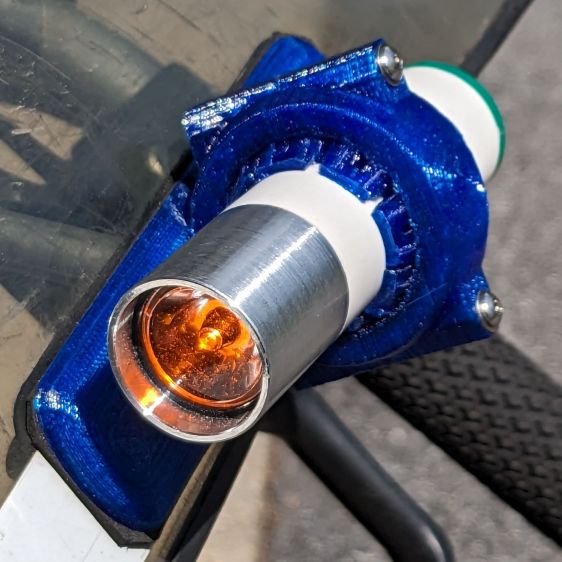
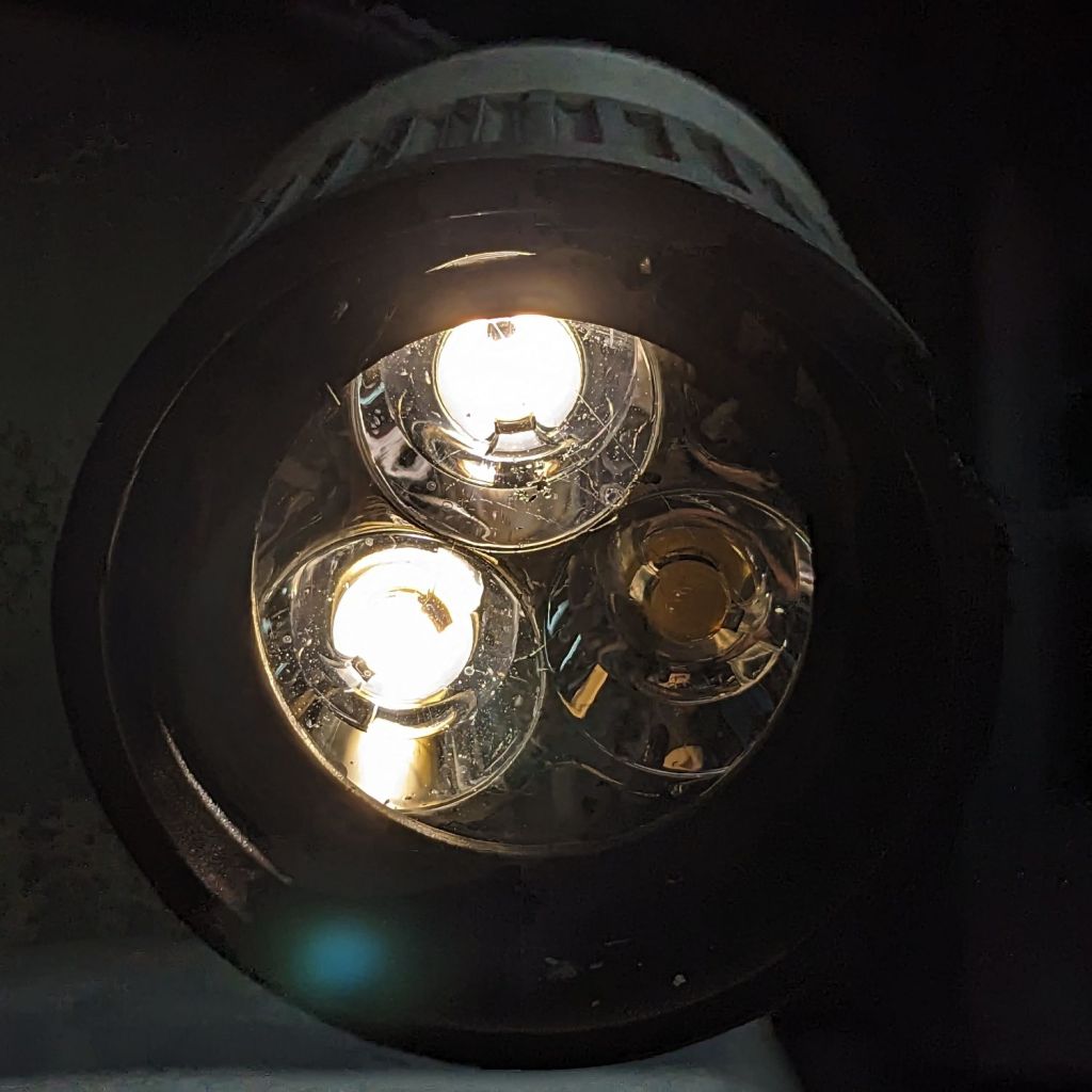
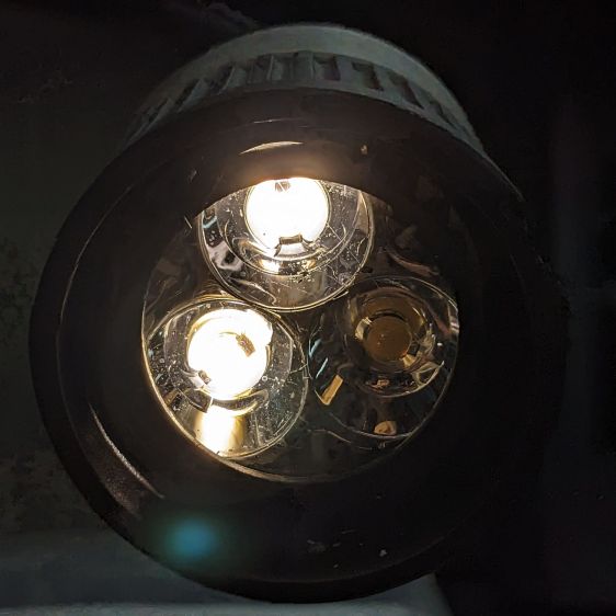
The running lights have the same general structure as before and fit into the same front and rear holders:
Tour Easy Running Light – rear installed
I made the recess slightly deeper to provide a bit more protection to the lens:
Tour Easy Running Light – front installed
The lenses have a 10° beam angle, so a few more millimeters of sidewall doesn’t intercept much light.
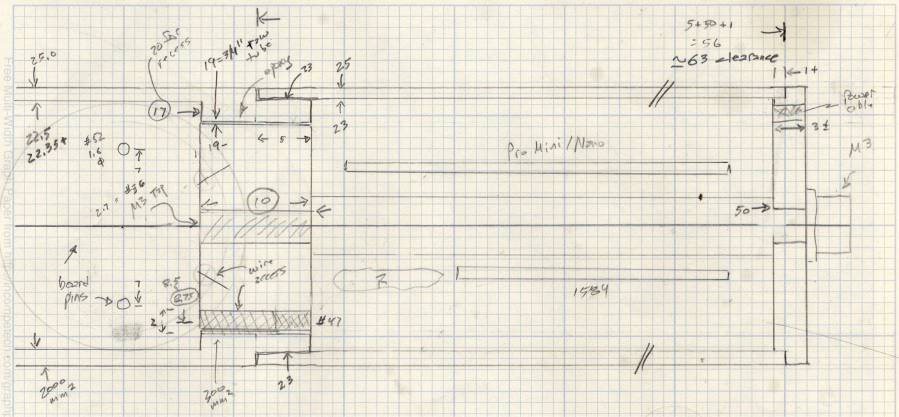
The layout doodle grew a few more notes:
Tour Easy running light – housing dimensions
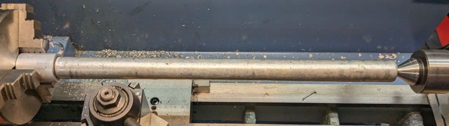
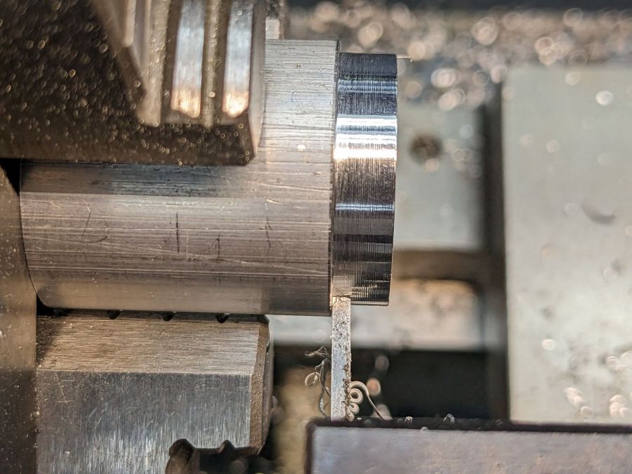
I had the good idea of boring the tube, knurling the rod, then epoxying the two together beforecutting the rod:
Tour Easy Running Light – heatsink curing
Which let the lathe hold them in perfect alignment during curing:
Tour Easy Running Light – heatsink plug alignment
The rod fits through the lathe spindle and I intended to use it as an arbor while turning the tube exterior, then cut the finished heatsink off flush.
Which really good idea lasted until the next morning, when I looked at the setup and immediately cut the rod flush with the tube. Because reasons, perhaps excess blood in my caffeine stream.
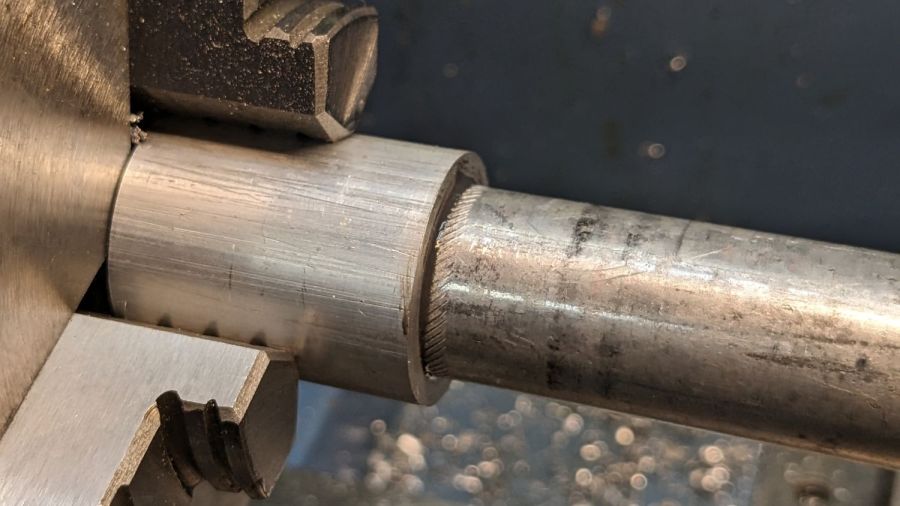
So I had to finish the heatsink on hard mode right up against the chuck:
Tour Easy Running Light – turning heatsink rebate
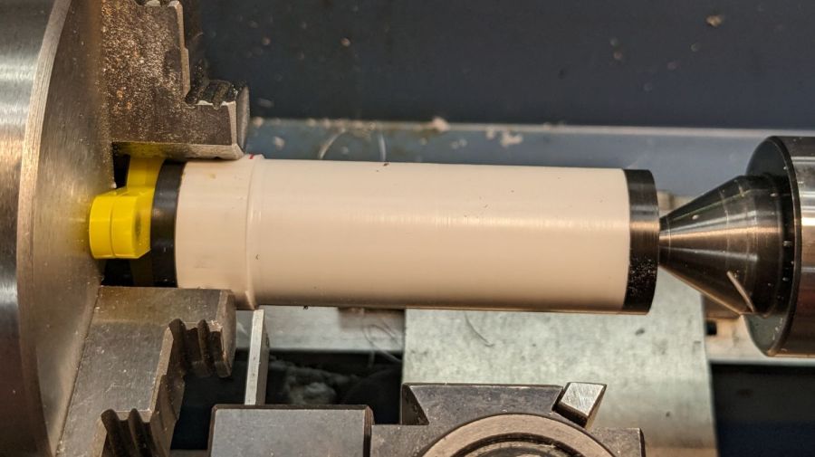
Flipping it around and gripping that little rebate to skim the OD down to 25 mm seemed fraught with peril, so I stabilized the open end with a chuck and plenty of oil; the live center was just too big around for the job.
After boring the PVC pipe to 23 mm ID, I made a pair of Delrin fixtures to simplify turning the exterior to 25 mm before parting it off:
Tour Easy Running Light – turning body OD
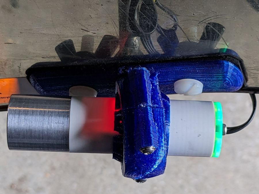
The PVC is so thin the Arduino’s LEDs shine right through:
Tour Easy Running Light – installed top view
The radioactive green endcap is ordinary laser-cut fluorescent edge-lit acrylic with sunlight through the garage door on the left. I used red acrylic for the taillight to encourage their separate identities.
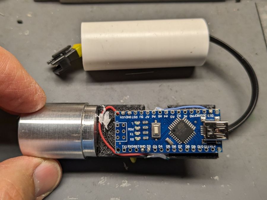
The knockoff Arduino Nano fits on one side of the support plate:
Tour Easy Running Light – Arduino view
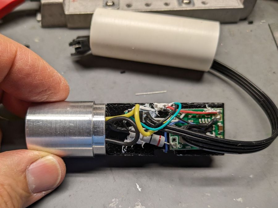
And the current regulator on the other:
Tour Easy Running Light – current regulator
Because these run from a dedicated 6.3 V step-down regulator, rather than the Bafang controller’s headlight output, the 2.0 Ω sense resistor sets the LED current to 0.8 V / 2.0 Ω = 400 mA, which is pretty close to the LED 1 W spec.
The white blob at the end of the two ribbon cable wires is the optoisolator pulling down a pin when the LIGHT signal is active, telling the firmware to stop the normal blink pattern and just turn the LED on all the time. This will come in handy if I ever do any night riding.
The LED is epoxied to the aluminum shell (with metal-filled JB Weld) and the whole affair never gets more than comfortably warm even with the LED running constantly.
I think they came out All Good™, despite various blunders along the way.
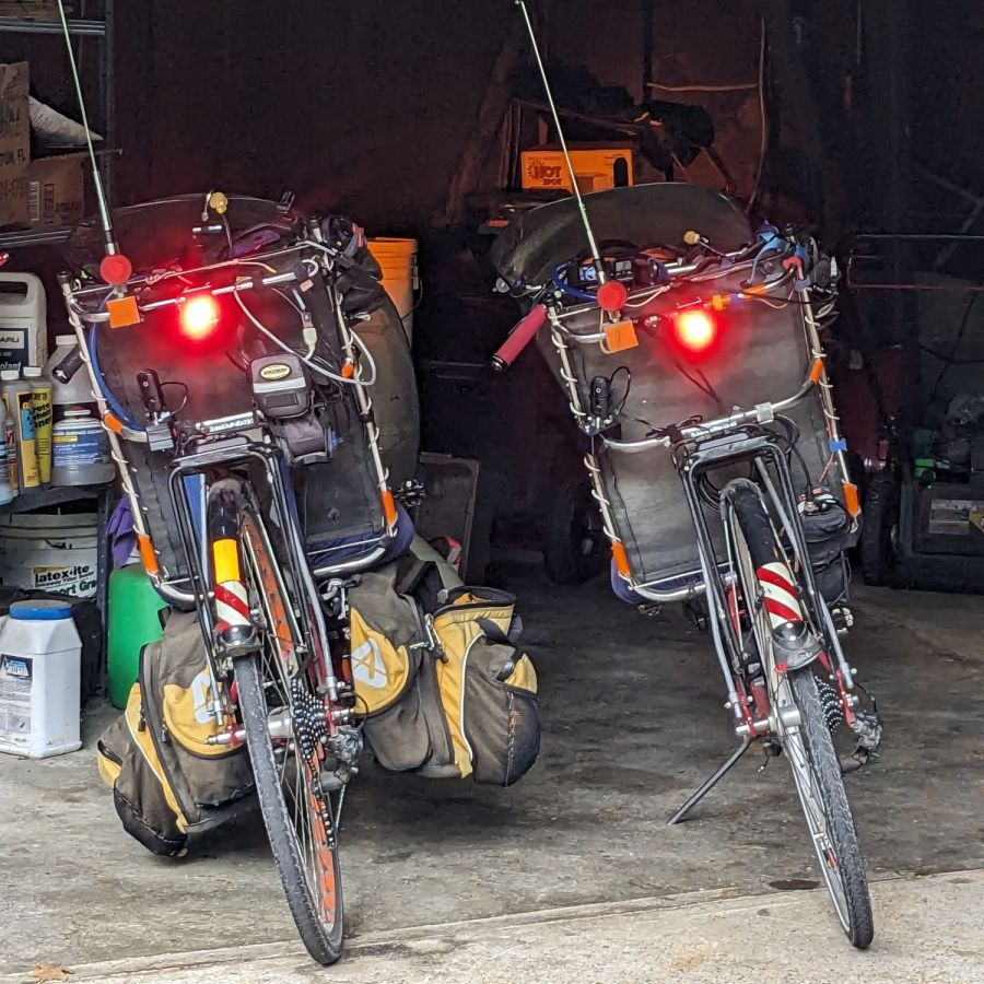
Having just finished another set of daytime running lights, we once again have a matched pair of Tour Easy recumbents:
Tour Easy Running Light – two tail lights
Although both ‘bents have Bafang 750 W motors with 48 V lithium batteries and both motor controllers have “light” outputs, they are different.
The controller on Mary’s bike (on the right) has a 6.3 V output that goes active when you press the 500C display’s + button for a few seconds. Those running lights simply use the light output for power, with a bit of tweakage to keep their current draw within the 500 mA limit.
The controller on my bike (on the left) has a 12 V output that goes active when I press-and-hold the headlight button on the DPC-18 display’s pad. Unlike the 500C, however, the DPC-18 dims its display when the lights are on, rendering it completely illegible in sunlight.
Because the running lights must operate with the headlight output inactive, a buck converter from a randomly named Amazon seller steps the 48 V battery down to 6.3 V. Note that the usual buck converters have a 36 V upper limit, so you want one with an LM2596HV regulator.
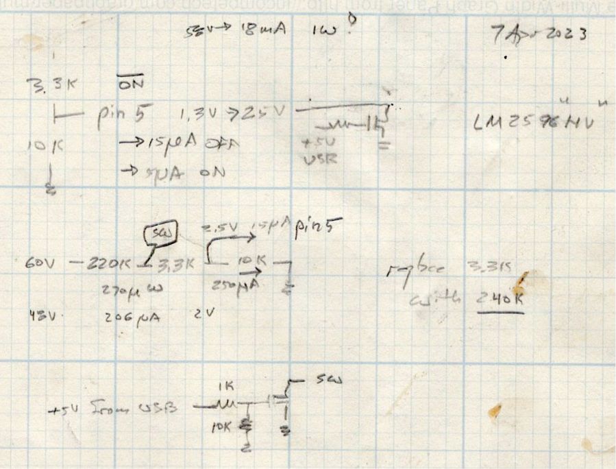
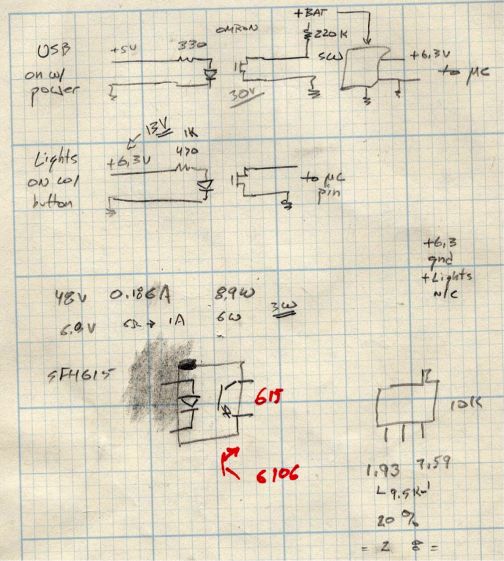
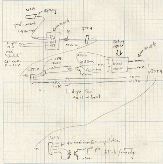
Because the regulator should be turned off when the motor controller is off, it must have a control input to enable / disable it; even if the regulator has the input pin, most boards don’t bring it out to a pad. The PCB I used has a SW input that must be low to enable the regulator, as shown in the middle doodle amid these scratches:
Tour Easy running light – buck converter SW control doodles
The SW pad on the PCB drives a voltage divider made from a 3.3 kΩ and a 10 kΩ resistor, with the regulator’s control (pin 5) looking at the junction. Running the numbers suggested a 220 kΩ resistor from the battery + terminal would provide enough current to hold the pin high, while not drawing more than a few hundred microamps, and a transistor could pull it low to turn the regulator on.
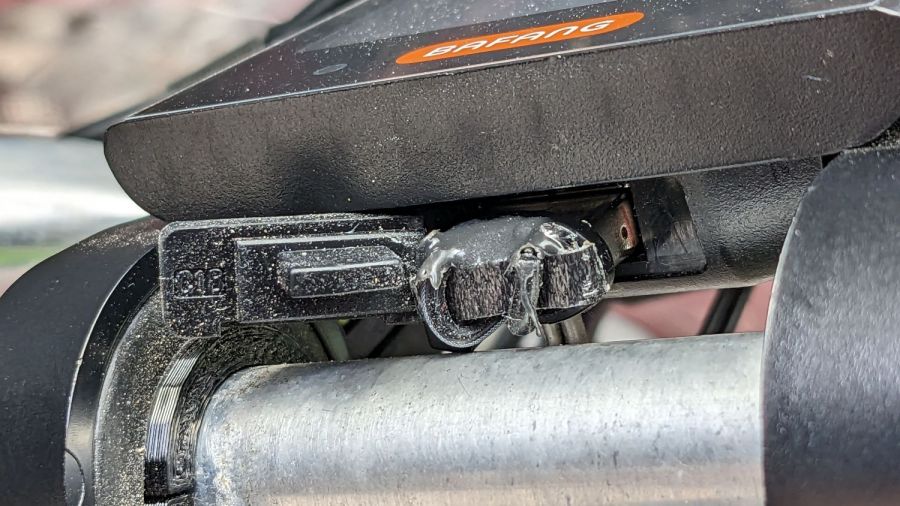
The DPC-18 display has a USB port to charge your phone on the go, so I hijacked that to get +5 V when the controller is turned on:
Tour Easy Running Light – Bafang DPC-18 USB plug
It’s a cut-down USB breakout board with two 24 AWG wires stripped from a ribbon cable soldered in place and coated with epoxy. The silicone port cover sticks out on the left; I eventually jammed it under the display panel in lieu of cutting it off.
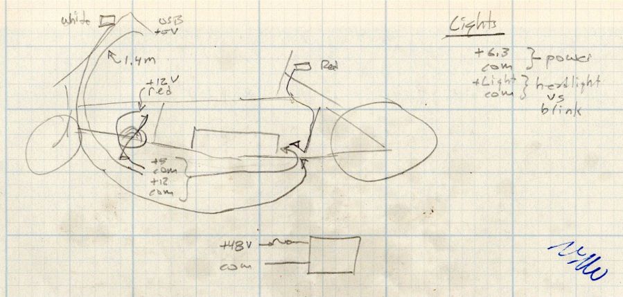
Although I want the running lights on whenever the controller is on, It Would Be Nice™ to have a steady headlight / taillight in the unlikely event I ever ride after dark. With that in mind, the USB power pair joins another pair from the motor controller’s LIGHT connector (via a red 2-pin Juliet plug), so the firmware can tell when the headlights should be on, and the resulting 4-wire ribbon cable wanders off to the battery mounting plate:
Tour Easy running light – wire routing doodle
The connectors along the way are 4-pin JST-SM 2.5 mm, which are most certainly not watertight. We’re fortunate in being able to not ride in the rain whenever we want, so the connectors won’t be exposed to water very often.
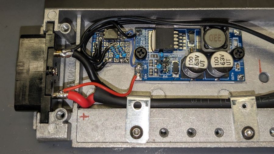
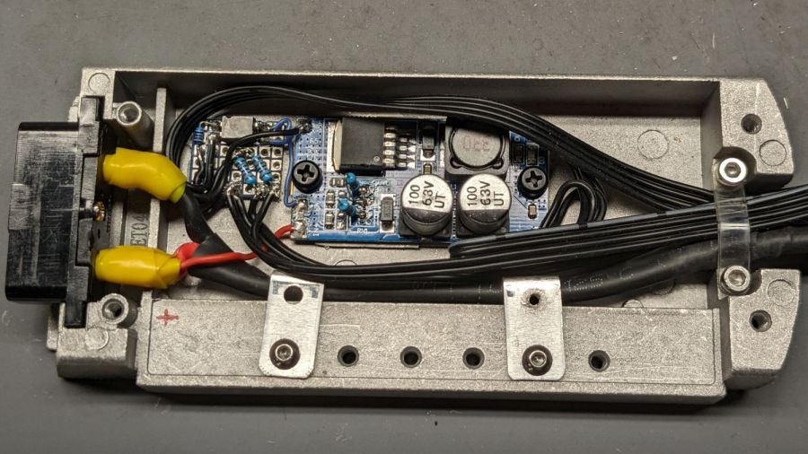
The battery mounting plate has an aluminum casting with a small compartment, probably intended for a complete e-bike controller, that just barely holds the hardware required to produce the 6.3 V supply:
Tour Easy Running Light – Bafang battery base circuitry – detail
Yes, those exposed battery terminals with soldered-on wires got a silicone tape wrap. No, there are no fuses involved. The two steel brackets holding the main power cable in place came pre-bent and pre-drilled in a random piece of scrap harvested from some dead equipment; they’re screwed into pre-tapped holes intended for the six TO-220 style power transistors of the missing motor driver.
The perfboard in the upper left holds an optoisolator for the USB power → SW input and a pair of resistors for the LIGHT signal to the headlight and taillight:
Tour Easy running light – control doodles
The optoisolators come from an ancient surplus deal; the bag I thought contained unmarked SFH615 parts apparently got mixed with some unmarked SFH6106 parts with the opposite transistor pinout.
The sketched trimpot in the lower right was on the buck regulator board, where it stood just an itsy too tall to fit the space available. Given that I would never adjust it, I set it for 6.3 V, removed it, measured the resistances, substituted fixed resistors, and the board should produce 6.3-ish V forevermore.
The regulator sits atop heatsink tape on a brass sheet with more heatsink tape isolating it from the housing and two nylon screws holding the stack in place.
With the various cables soldered in place:
Tour Easy Running Light – Bafang battery base circuitry – wired
Daubing urethane adhesive into each pocket, sliding a tiny magnet atop the goo, and flipping them over onto a sheet of plastic atop the surface plate to let them cure went about the way you’d expect. Given the state of my fingertips, however, I was not about to fiddle with the phone / camera / anything, but it really did happen.
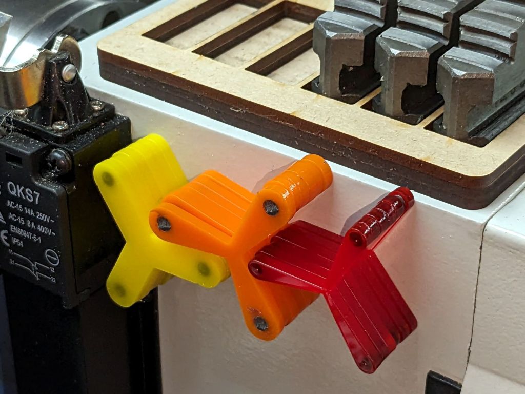
The final result:
Lathe Chuck Stops – on-lathe storage
The alert reader will notice the slight gap under the left leg of the first orange stop, which provides a good introduction for a few things that should happen differently the next time I do something like this.
To my credit, I got all but one of the 54=3×6×3 magnets into their pockets in the same orientation. That’s gotta count for something and, hey, that orange stop sticks to the chuck just fine.
That one also suffered from my failure to switch the Axis UI to metric units before touching off the Z axis at 0.1 mm, thereby putting the Z=0.0 level 2.53 mm below the surface. Fortunately, the 3 mm MDF baseplate prevented that error from creating three pockets in the tooling plate, although it did produce holes instead of pockets in the stop.
I dropped the magnets into the thru-cut stop on the surface plate and dabbed some adhesive atop the magnets to bond them into their holes. This worked fine and led me to suspect the easiest way to make these stops would be to just laser-cut the holes and skip the whole CNC thing.
The disadvantage of cutting the holes through is that adhesive will inevitably ooze out around the magnet and mess up the bottom surface of the stop. Sticking both the stop and the magnets onto kapton tape seems like it should seal well, but liquid always finds a way.
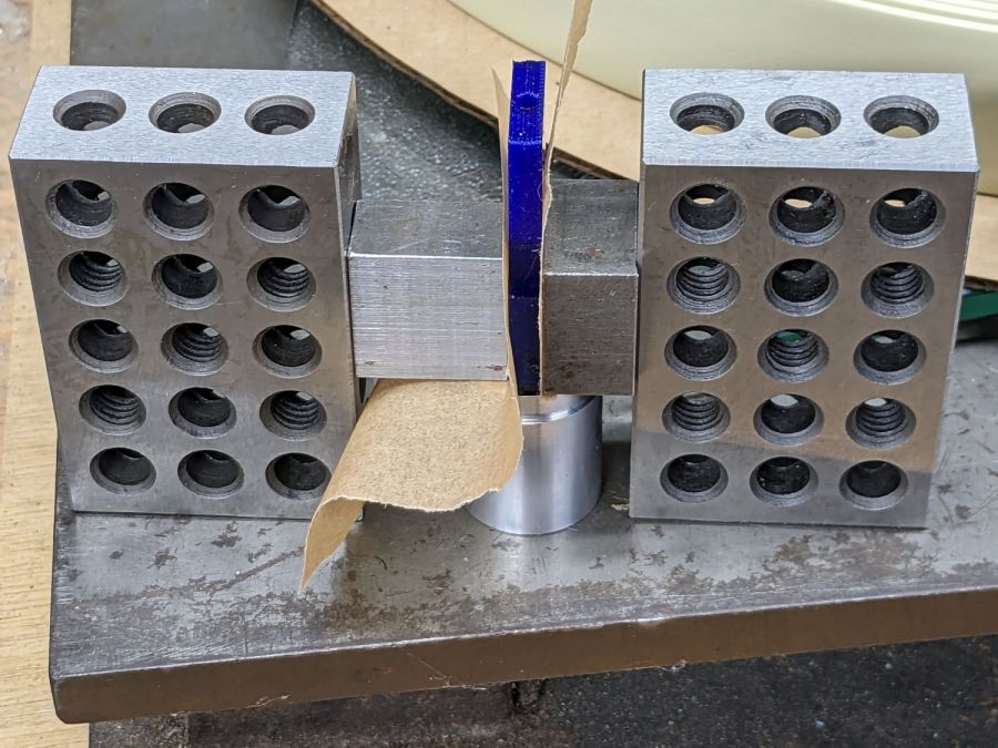
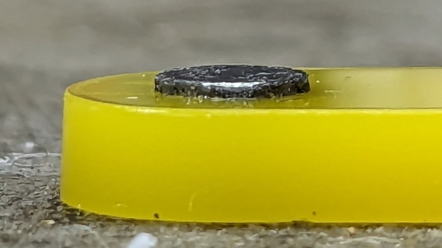
In any event, the two-part urethane adhesive (JB Plastic Bonder) expands slightly as it cures, which is great for gap filling and not so good for precision bonding. With the pockets in the other 17 stops arranged open-side down, the magnets held themselves firmly to the plastic sheet atop the surface plate and the expanding urethane pushed the acrylic stop upward, leaving the magnets standing slightly proud of the stop’s surface:
Lathe Chuck Stops – protruding magnet
Not by much, mind you, but not what I wanted, having painstakingly cut the pockets 2.2 mm deep for a 2.0 mm magnet.
Next time, dot some slow-cure clear pouring epoxy in each pocket, put the stop on the surface plate with the pocket facing up, then drop the magnet in place. The magnet pulls itself into the pocket, the epoxy doesn’t expand, any overflow will fill in over the magnet, and anything sticking out can be sanded off.
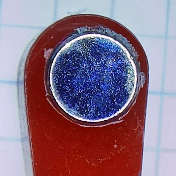
The fixtures worked well and aligned perfectly on the Sherline’s tooling plate. The 0.1 mm outset around the stops in the chipboard probably wasn’t needed, although the total repeatability seemed to be around 0.2 mm and pocket position errors are visible only on the smallest (red) stops:
Lathe Chuck Stops – misaligned pocket
All in all, this turned out pretty well. Next time will be even better!
#<chuckrad>=20.000                  (radius to center of magnet)
#<chuckjaws>=3                      (number of jaws)
#<chuckang>=[360.0/#<chuckjaws>]    (angle between jaws)

#<bitrad>=[2.900/2]                 (cutter radius)

#<pocketrad>=[4.100/2]              (magnet pocket radius)
#<pocketdeep>=2.200                 ( … depth)
#<xoffs>=[#<pocketrad>-#<bitrad>]   (pocket center to cutter center)

#<safez>=20.0                   (above all the clamps & gadgets)

G21 G54 G80 G90 G94             (metric!)

F600                            (full speed for the Sherline)

G0 Z#<safez>
Obviously, those magic numbers must match the laser-cut blanks, the magnets, the cutting bit in the spindle, the clamps on the table, the speed of the machine, and everything else you overlooked.
So. Much. Pain.
Knowing the angle to the current pocket, polar coordinate notation gets to the center point, with a jaunt in relative motion to the starting point for the helix into the pocket:
That dance produced rounder pockets with cleaner bottoms than just a single helix down and a straight pull upward.
Then set up for the next hole and clean up after the last one:
G0 @#<chuckrad> ^#<ang>         (back to center)
G0 Z#<safez>

#<ang>=[#<ang>+#<chuckang>]     (set up next hole)
O100 ENDREPEAT

G0 Z[2*#<safez>]
G0 X0 Y0

M2
I ran the Sherline XY axes at their 600 mm/min top speed, the spindle at 10 kRPM with a shiny new 3 mm (nominal!) cutter, ramped into the helix at ≅10° (on a 1 mm circle!), and it sliced the acrylic into nice chips without getting all melty.
Unlike with Javascript, when you get something wrong in G-Code, you can hear the crash.
The LinuxCNC pocketing code as a GitHub Gist:
This file contains hidden or bidirectional Unicode text that may be interpreted or compiled differently than what appears below. To review, open the file in an editor that reveals hidden Unicode characters.
Learn more about bidirectional Unicode characters