Ed Nisley's Blog: Shop notes, electronics, firmware, machinery, 3D printing, laser cuttery, and curiosities. Contents: 100% human thinking, 0% AI slop.
Category: Science
If you measure something often enough, it becomes science
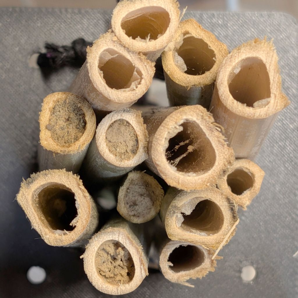
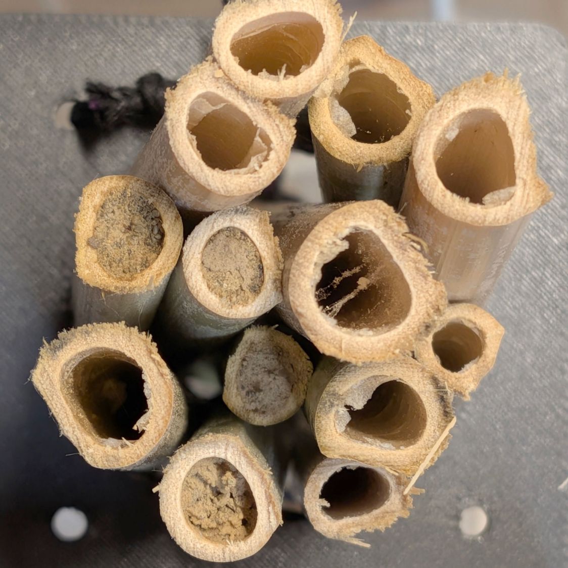
One of the bundles of small (a few mm ID) stalks on the kitchen window:
Bee Tunnel Nest – small A
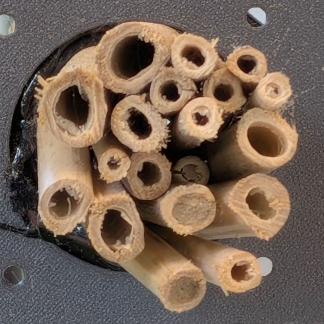
Another bundle of small stalks on a window a dozen feet away:
Bee Tunnel Nest – small B
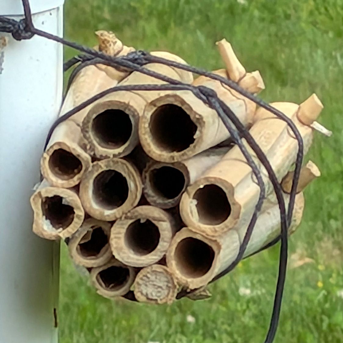
A bundle of medium (five to ten mm ID) stalks lashed to a downspout:
Bee Tunnel Nest – medium
Unlike the mud dauber wasps decorating our previous house, these little bees dart in and out without announcing their presence: we’ve never seen them at work.
Assuming a single bee works on each bundle, she apparently starts with the lowest stalk and moves upward after filling & capping it.
Larger bees have yet to discover the bundles of larger stalks out on the trees, but … so far, so good!
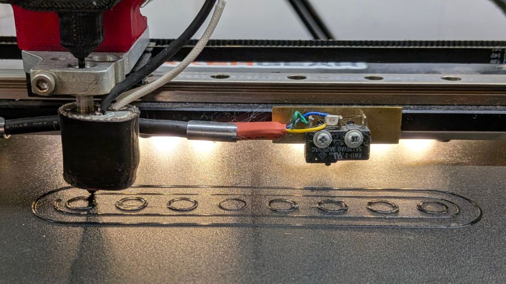
The first layer of a short TPU chain (about which, more later) came out vanishingly thin in the middle and much too thick on the ends:
Makergear M2 – TPU first layer
So: let the platform cool, scrape off the wreckage, set the nozzle for Z=2.0 mm, and measure the actual gap at various spots across the platform.
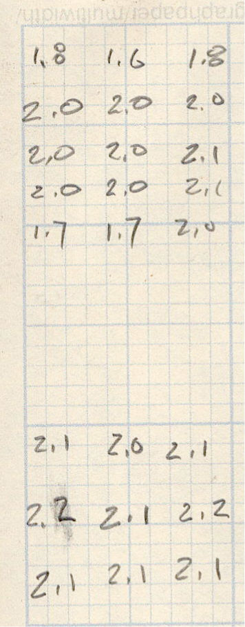
Those results are the top set of measurements:
Makergear M2 – BuildTak flatness check
The bottom set of measurements came from a similar test a few days later, after pulling the BuildTak plate off, doing nothing other than scrutinizing it, reinstalling it, and successfully printing several TPU chains of varying design, none of which had any first-layer problems. The platform is slightly too high along the +Y and -Y edges (rear and front), with no bow worth mentioning.
My measurements are, perforce, done with a cold platform, for obvious reasons, and the TPU prints at 50 °C. I have the uneasy feeling the heater / BuildTak magnetic base can bow upward in the middle while it heats, then flatten out after a while at a stable temperature. The good news: it’s not permanently bent.
More study is needed, including thinwall boxes after letting the platform soak at 50 °C for varying times.
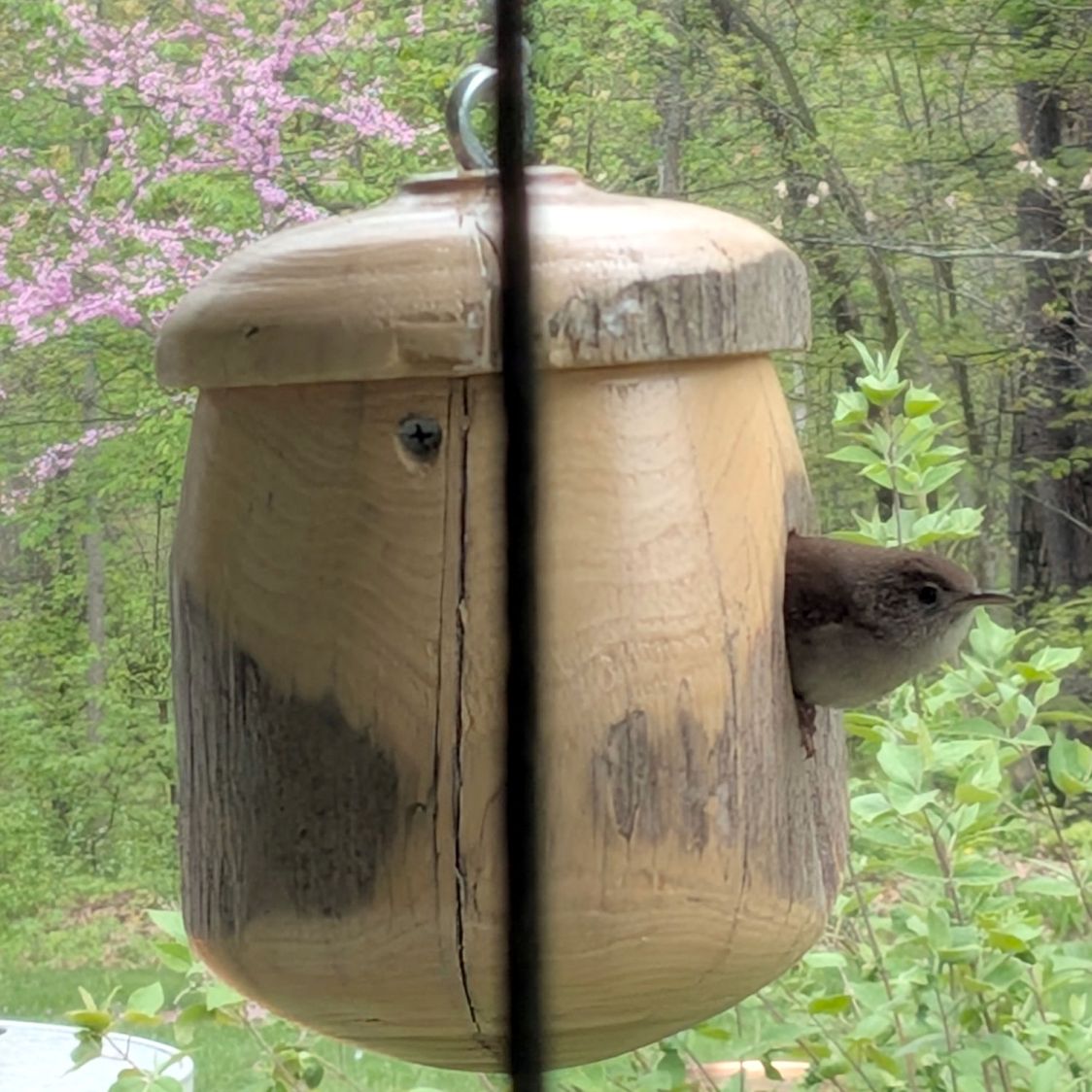
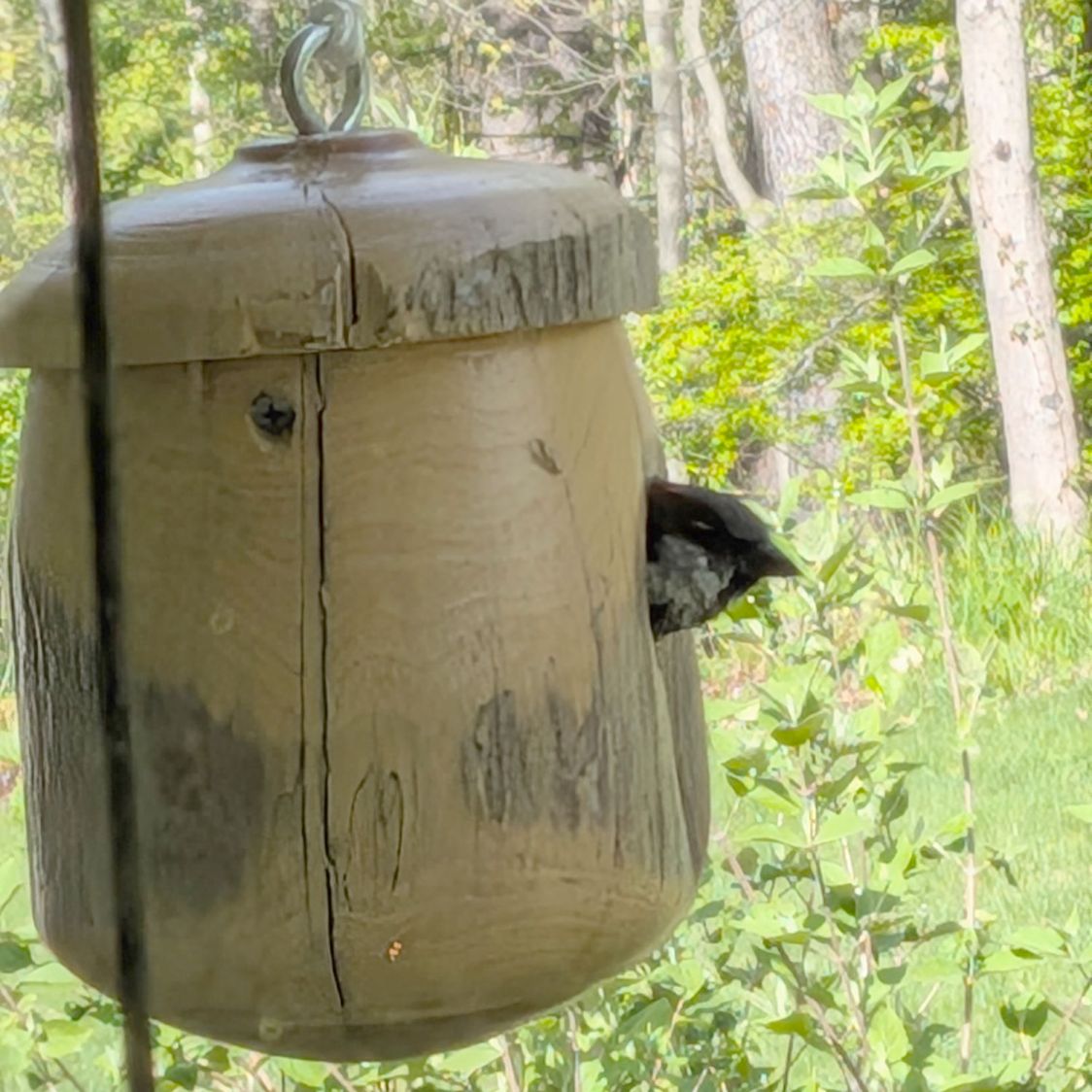
The entrance hole was 1-½ inch ⌀, a bit larger than the 1 inch ⌀ preferred by wrens and entirely suitable for the pair of House Sparrrows who also took an interest in the property:
Bird House – sparrow inside
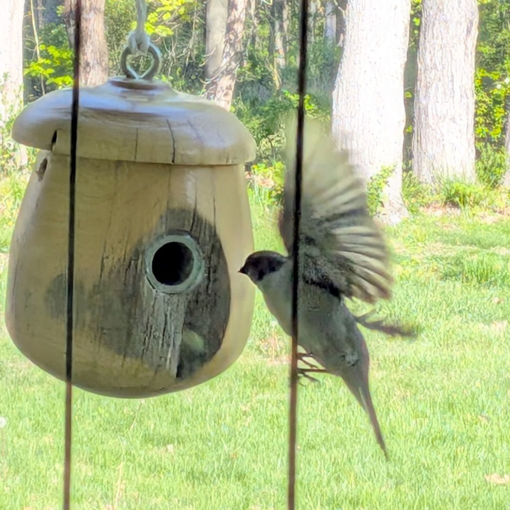
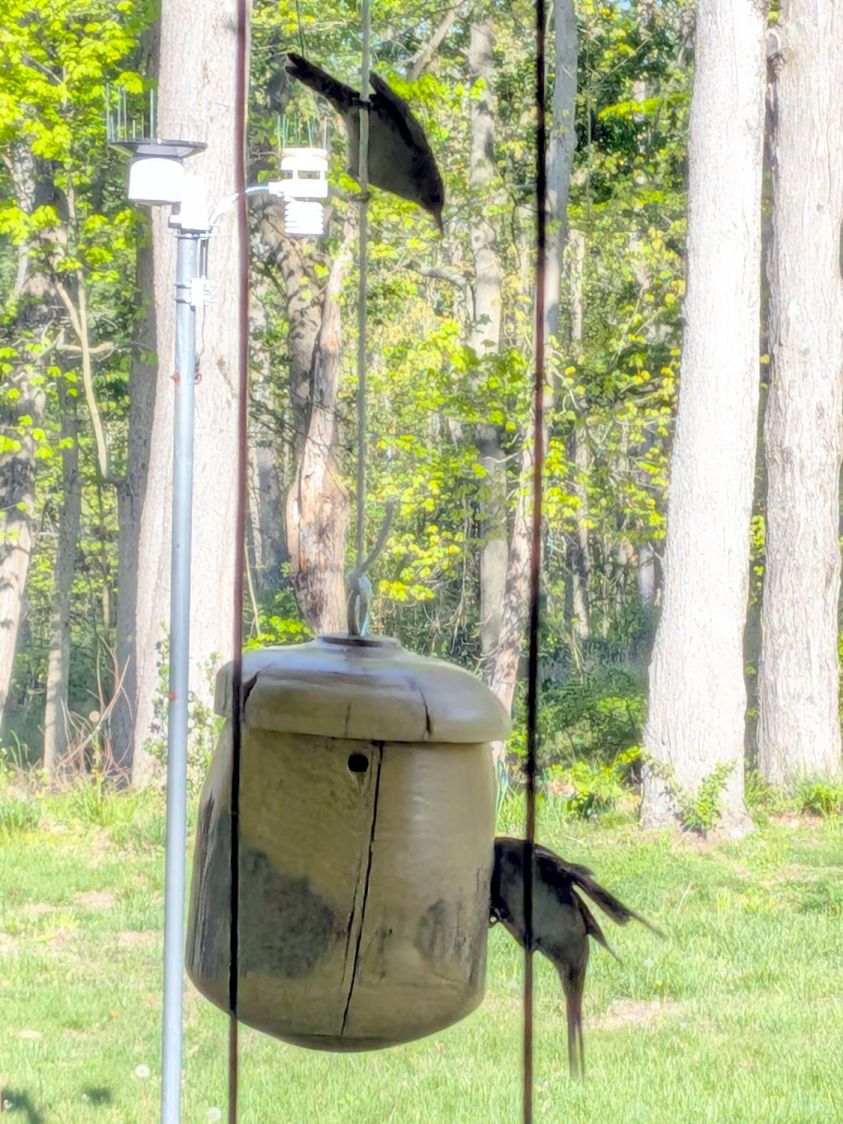
This led to considerable discussion and displays of outright hostility:
Bird House entrance reducer – wren vs sparrow
Sparrows and wrens disagree on nestbuilding materials, with the wrens hauling twigs into the box and sparrows hauling them back out again.
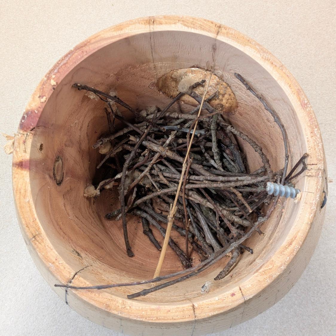
Because wrens have better PR agents than sparrows, I intervened by taking the box apart:
Bird House – nest base sticks
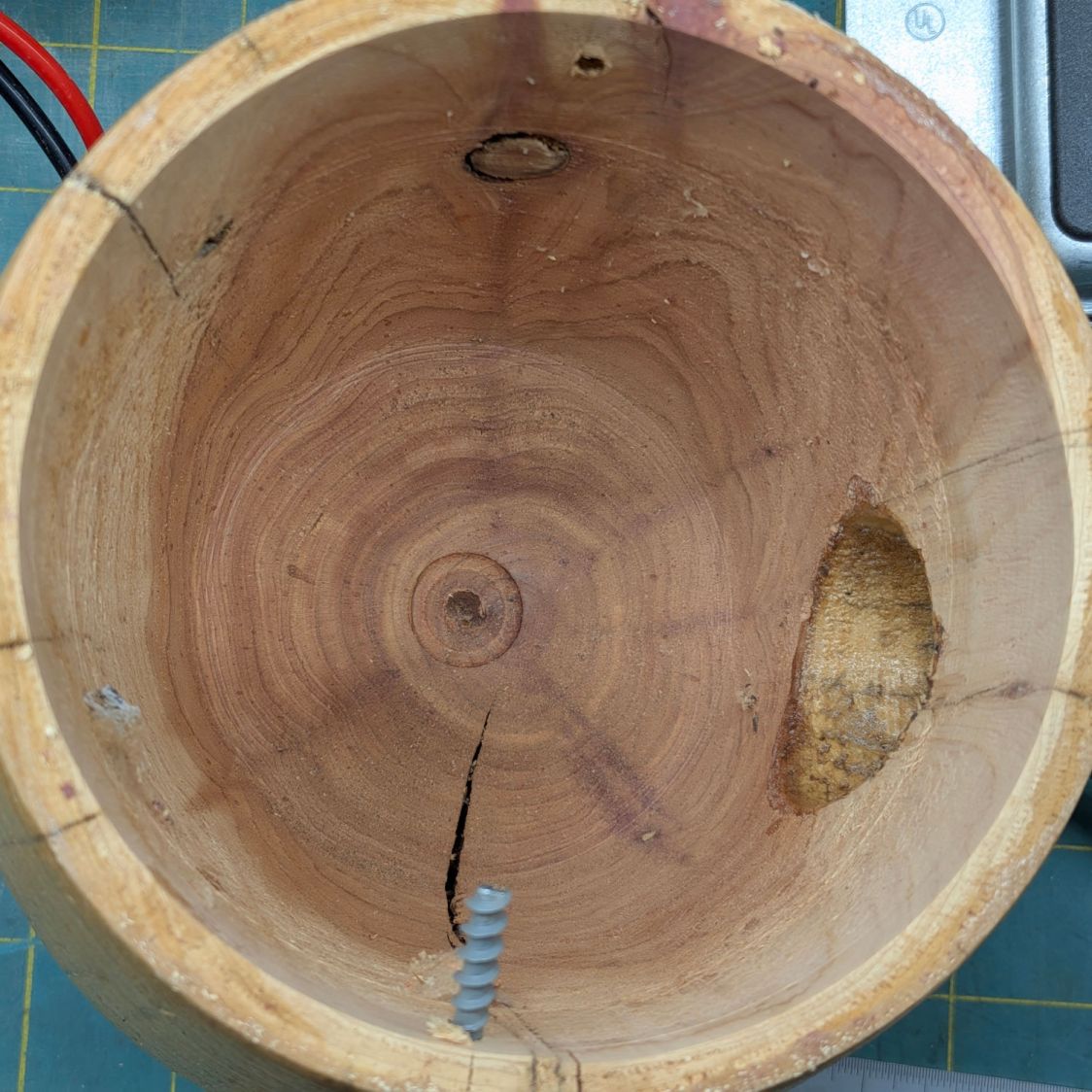
Although I realize that’s a lot of work for a small bird, I dumped the contents off the patio and set about reducing the entrance hole:
Bird House – interior cleared
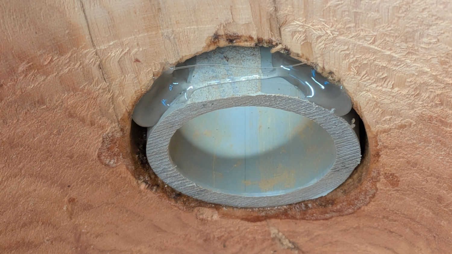
Because birds aren’t too fussy about looks, I sawed off half an inch of 1 inch (ID) CPVC pipe and glued it in the hole:
Bird House entrance reducer – interior glue
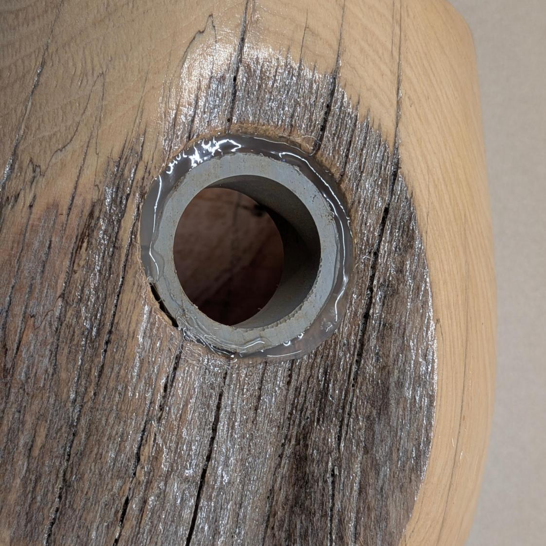
The outside looks marginally better:
Bird House entrance reducer – exterior glue
The sparrows continued to approach the hole at full throttle, deploying landing gear and speed brakes at the last possible moment:
Bird House entrance reducer – sparrow approach
But they no longer fit through the hole and eventually gave up trying. The wrens resumed hauling twigs, although we’re not certain they’ll finish the project, as birds tend to build several partial nests before selecting the final one.
Most of the PolyDryer boxes had the same humidity as before, so I didn’t disturb them. When the humidity starts to rise, then we’ll see what’s going on in there.
The PETG Orange meter continues to misbehave and has been glitching from 22% to 30%. The indicator card shows the humidity is around 10% inside and the relatively low weight gain suggests there’s not much water to be adsorbed.
The PETG-CF Blue spool is new and, once again, shows filament does not arrive bone-dry in the factory wrapper.
Those two boxes now have alumina beads.
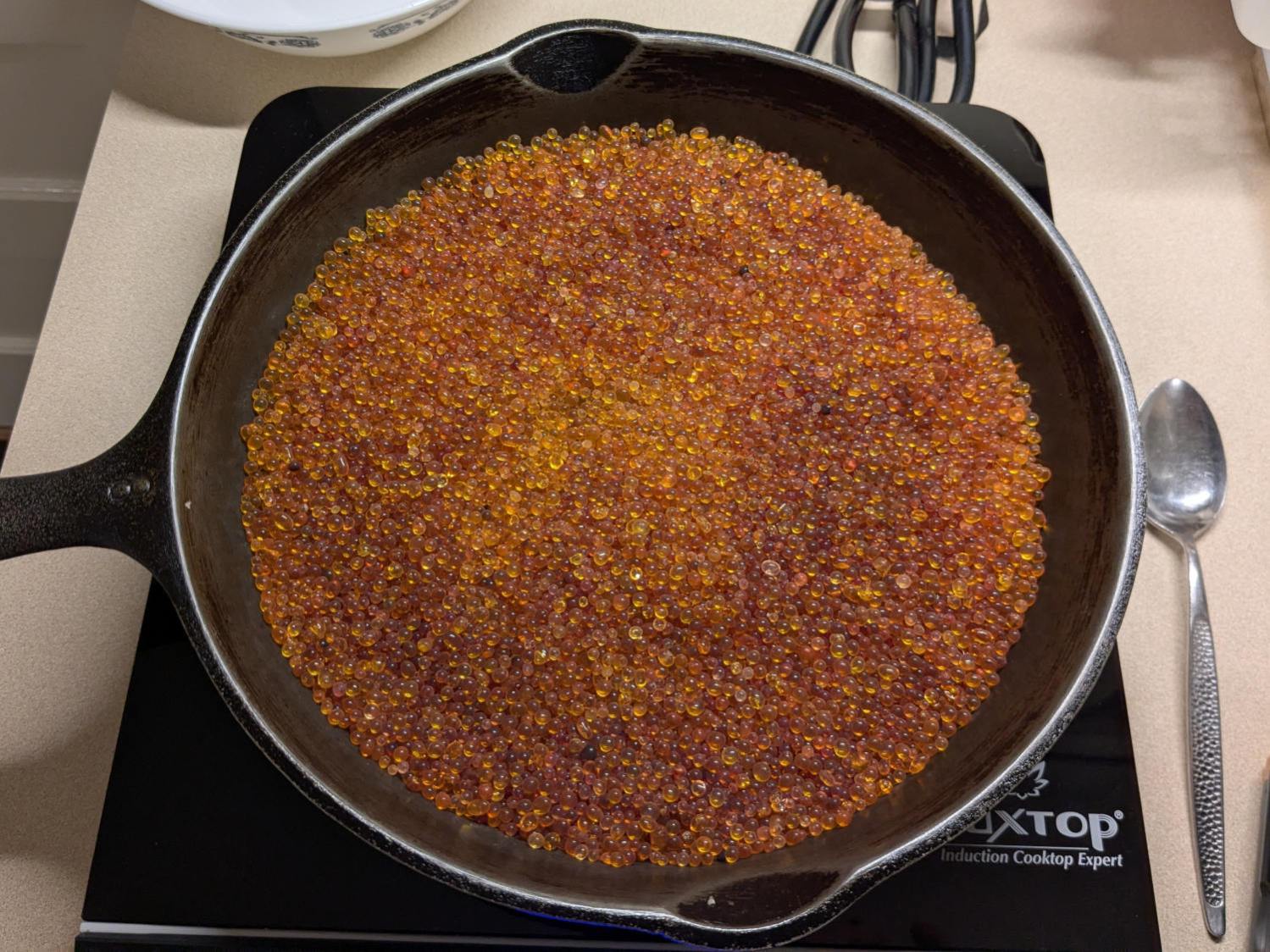
Dehydrating the jar of wet silica gel on the induction cooktop (set for 405 °F) sweated it down from 532 g to 503 g over the course of four hours, with nearly all of that change in the first two hours.
Obligatory photo from a while ago, because it looks pretty much the same now:
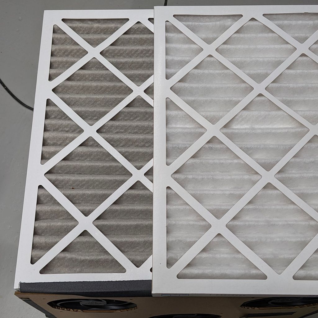
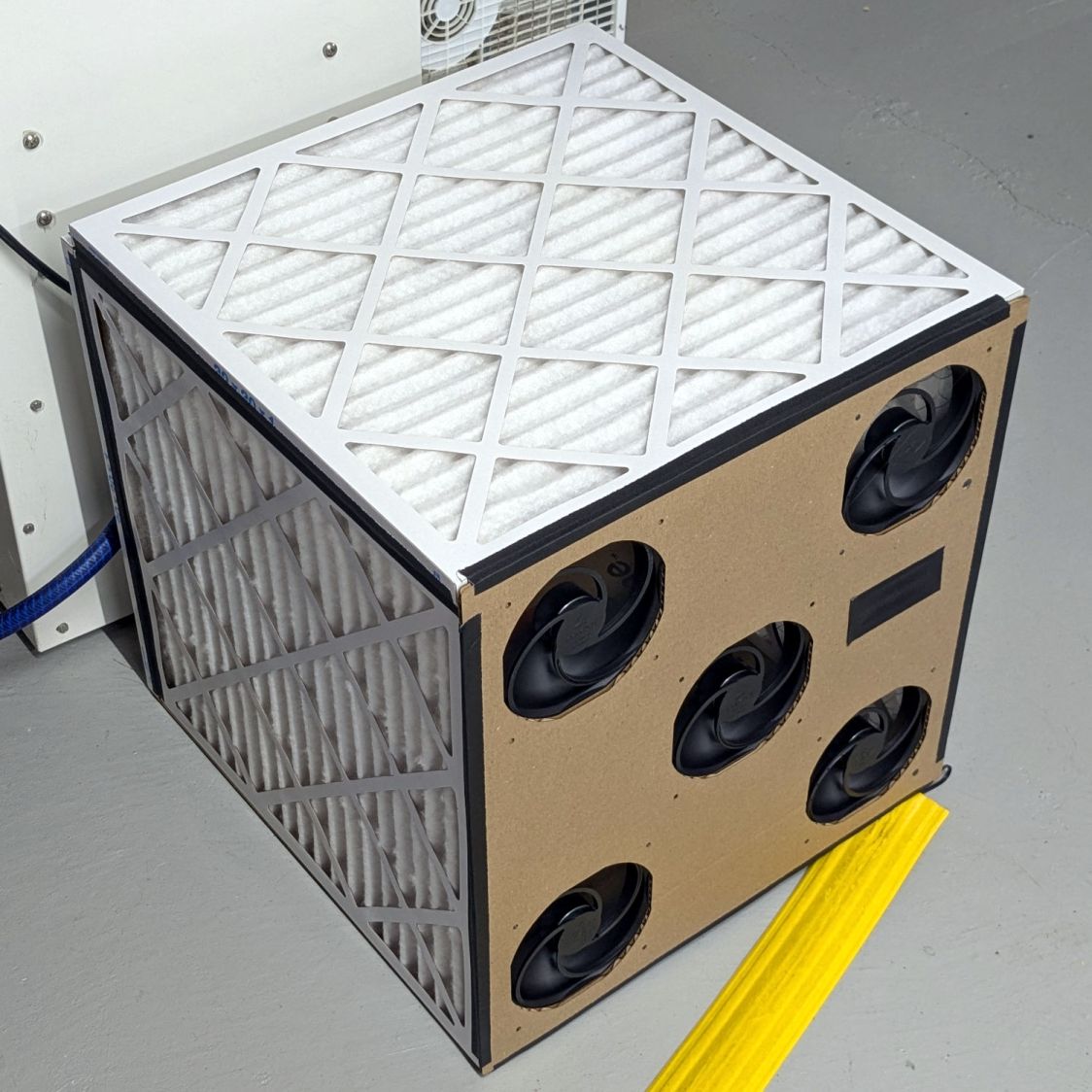
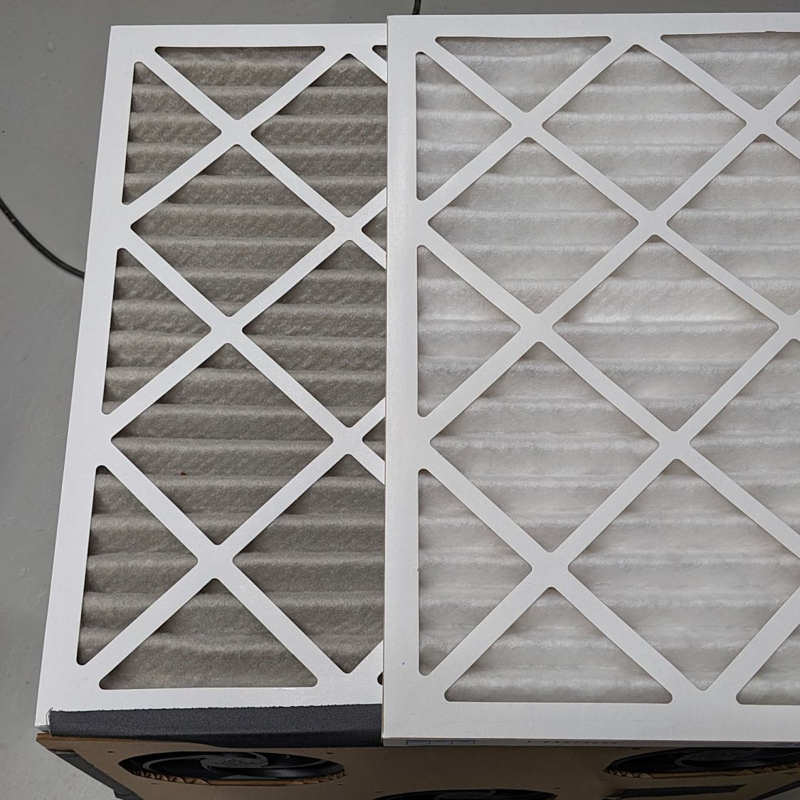
Running continuously for three months made the air filters look like this (with an unused filter on top for comparison):
Basement Air Filter Box – 3 months – A
I have not stretched the image contrast, so the new filter isn’t the pure white in the top picture, but it’s still about the same white as the cardboard frame. The floor is, indeed, painted gray.
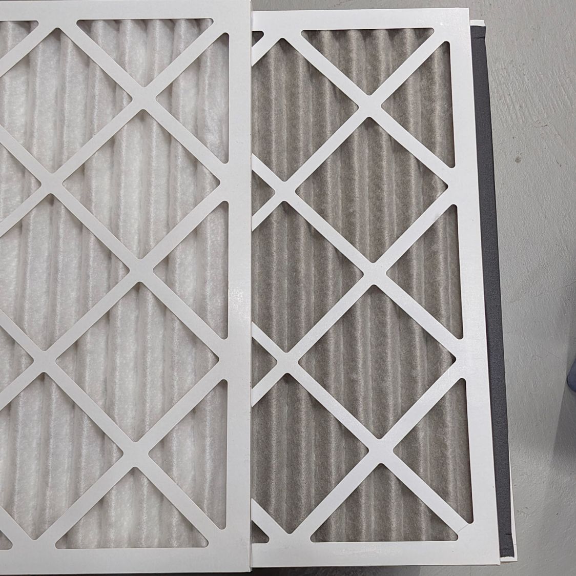
Looking at the pleats in the other direction to show I’m not making it up:
Basement Air Filter Box – 3 months – B
The inside surface of the filters has the same gray appearance. The fans are, unsurprisingly, immaculate.
Totally did not expect that!
The filters sport a MERV 13 rating and snag “most smoke” from the passing air, so they’ve been collecting any fumes not sucked out of the laser cutter, along with whatever arises from other Basement Shop™ activities.
So I’ll buy another set of filters, build another box, and see what accumulates during the next three months.
Based on the results from last time, I set the temperature to the cooktop’s maximum 460 °F and, bother fiddling with condensing the moisture on a lid, and let it cook.
Weighing the beads (about) once an hour:
Start: 700 g
1 hr: 678 g
2 hr: 666 g
3 hr: 661 g
The 39 g water loss is 5.6% of the wet weight and 5.9% of the dry weight, which is roughly the amount absorbed by both silica gel and alumina after a month or so in the filament boxes.
During those hours the surface temperature rose from 73 F to 190 °F, although the exact number depends on exactly where the IR thermometer was staring. Stirring the beads to get an average temperature might be more convincing, but not by much.
Exactly how dry the beads become after three hours remains unknown, but the temperature increase suggests most of the water has gone elsewhere.
Cooling the beads in a covered bowl and pouring them into a jug produced a total weight of 767 g, which settled at 770 g over the course of two days; the jug seems reasonably vapor-tight.
Alumina beads seem much less prone to damage by overheating than silica gel beads and have similar performance in the boxes, which makes them a strong contender for the next round.