Ed Nisley's Blog: Shop notes, electronics, firmware, machinery, 3D printing, laser cuttery, and curiosities. Contents: 100% human thinking, 0% AI slop.
Tag: Thing-O-Matic
Using and tweaking a Makerbot Thing-O-Matic 3D printer
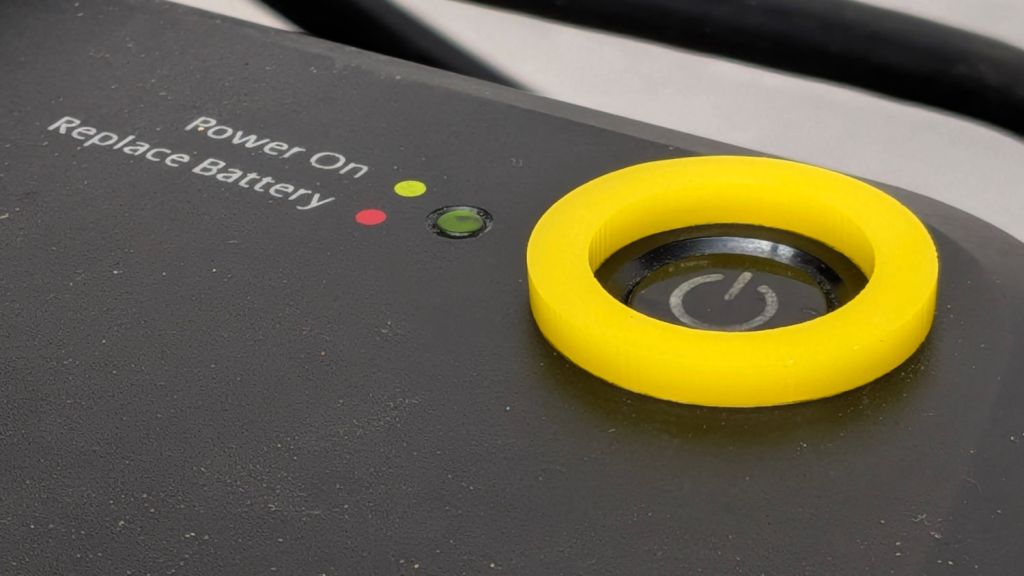
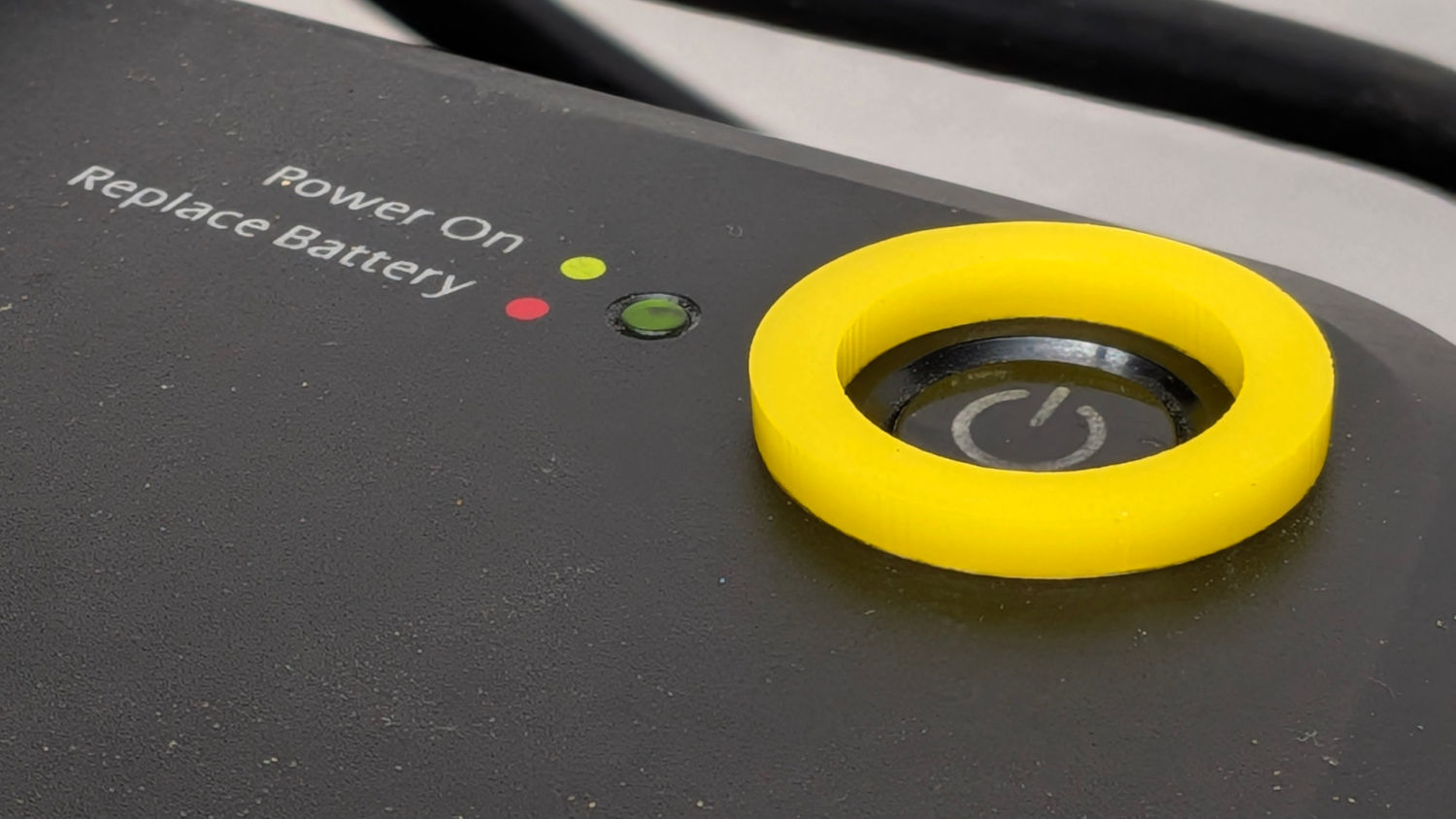
It turns out that dragging a USB cable across the top of the UPS for the PC (about to be) running the Sherline mill was enough to flip its flush-mounted hairtrigger power switch. Although I can’t recess the switch, adding a mollyguard should help:
Mollyguard – UPS power switch
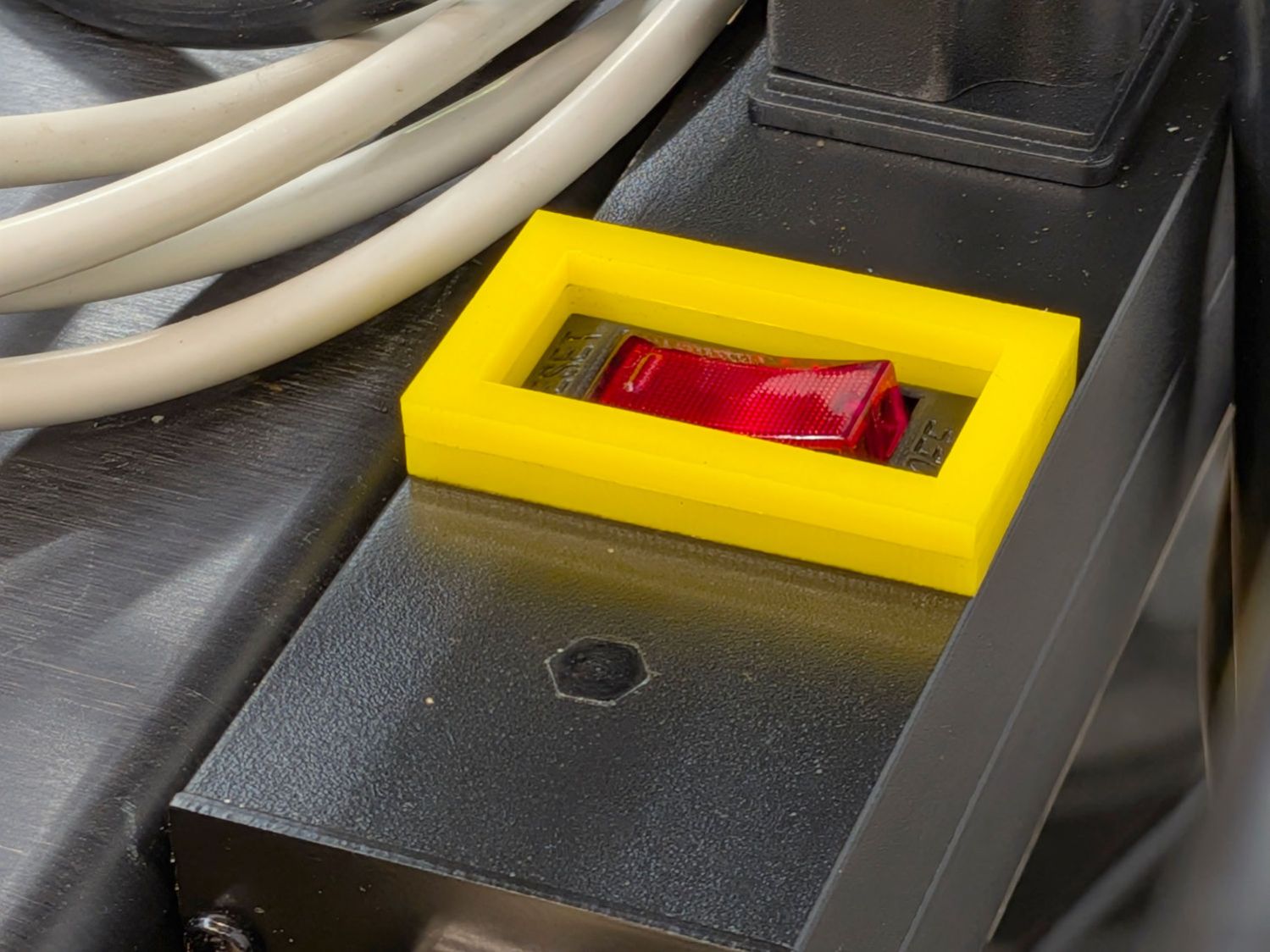
The power switches on the new outlet strips also seem unduly sensitive and a preemptive strike seemed in order:
Mollyguard – outlet strip switch
Two layers of 3 mm acrylic just barely clear the switch, but should prevent casual trips. AFAICT, the little hexagonal shape fills the hole for an indicator LED this strip doesn’t have.
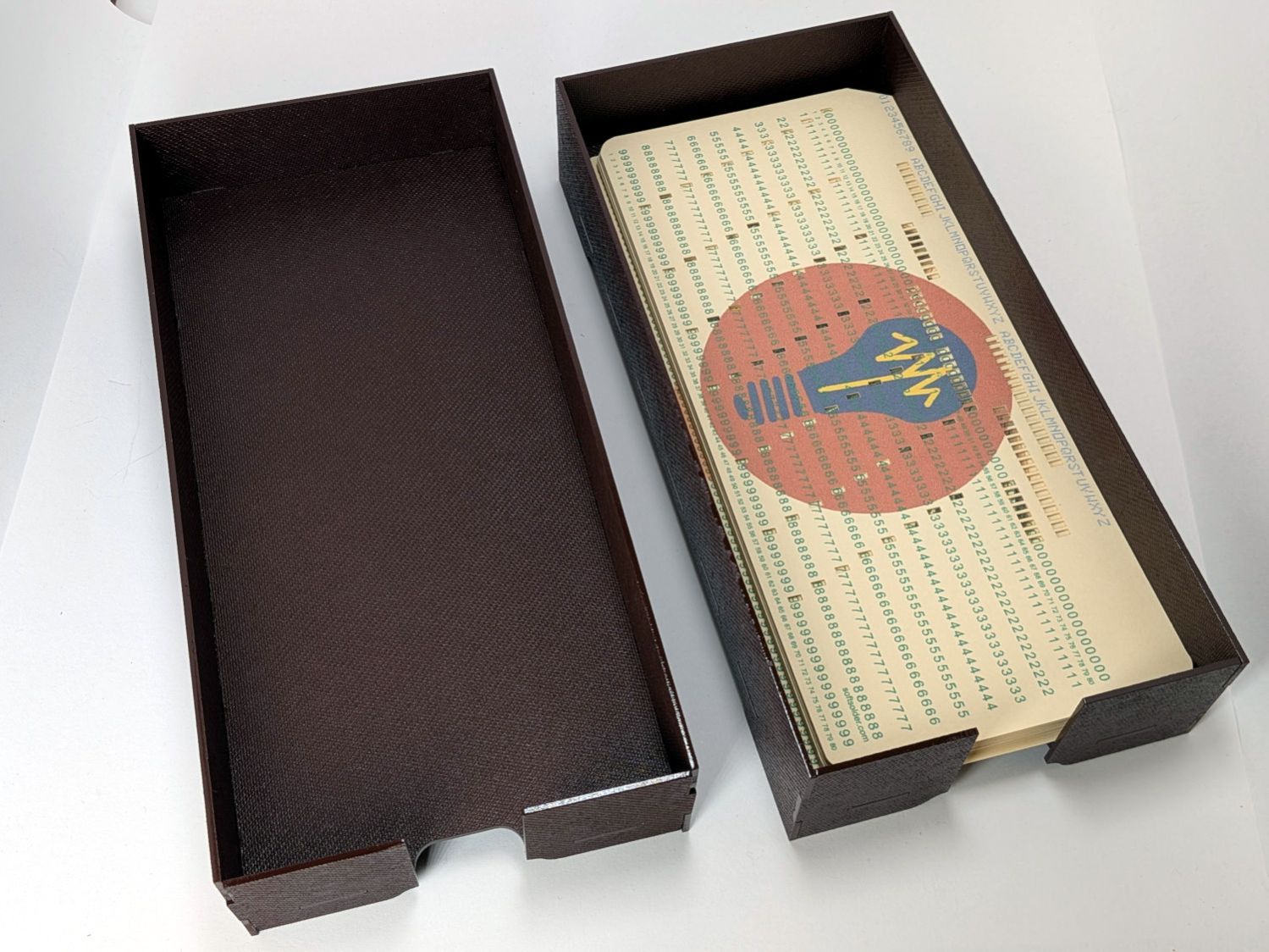
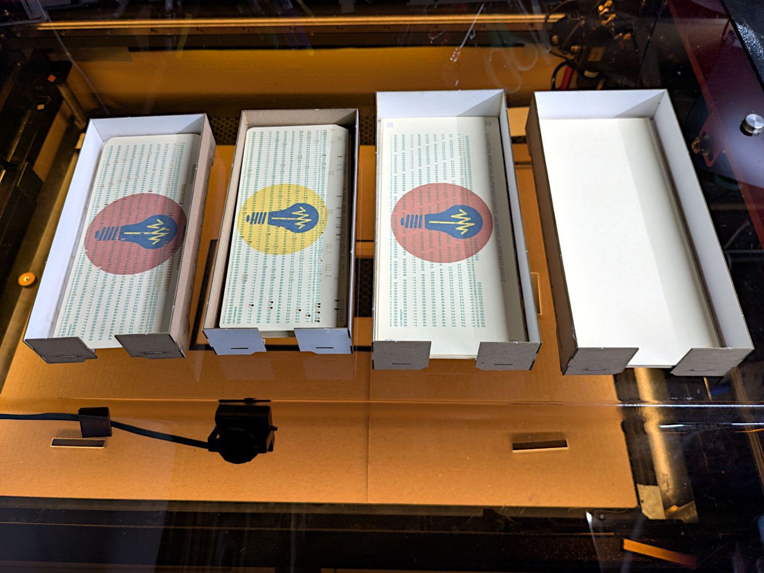
If you must have a stack of punched cards on your desk, a nice tray does wonders for the office decor:
Card Storage Tray – overview
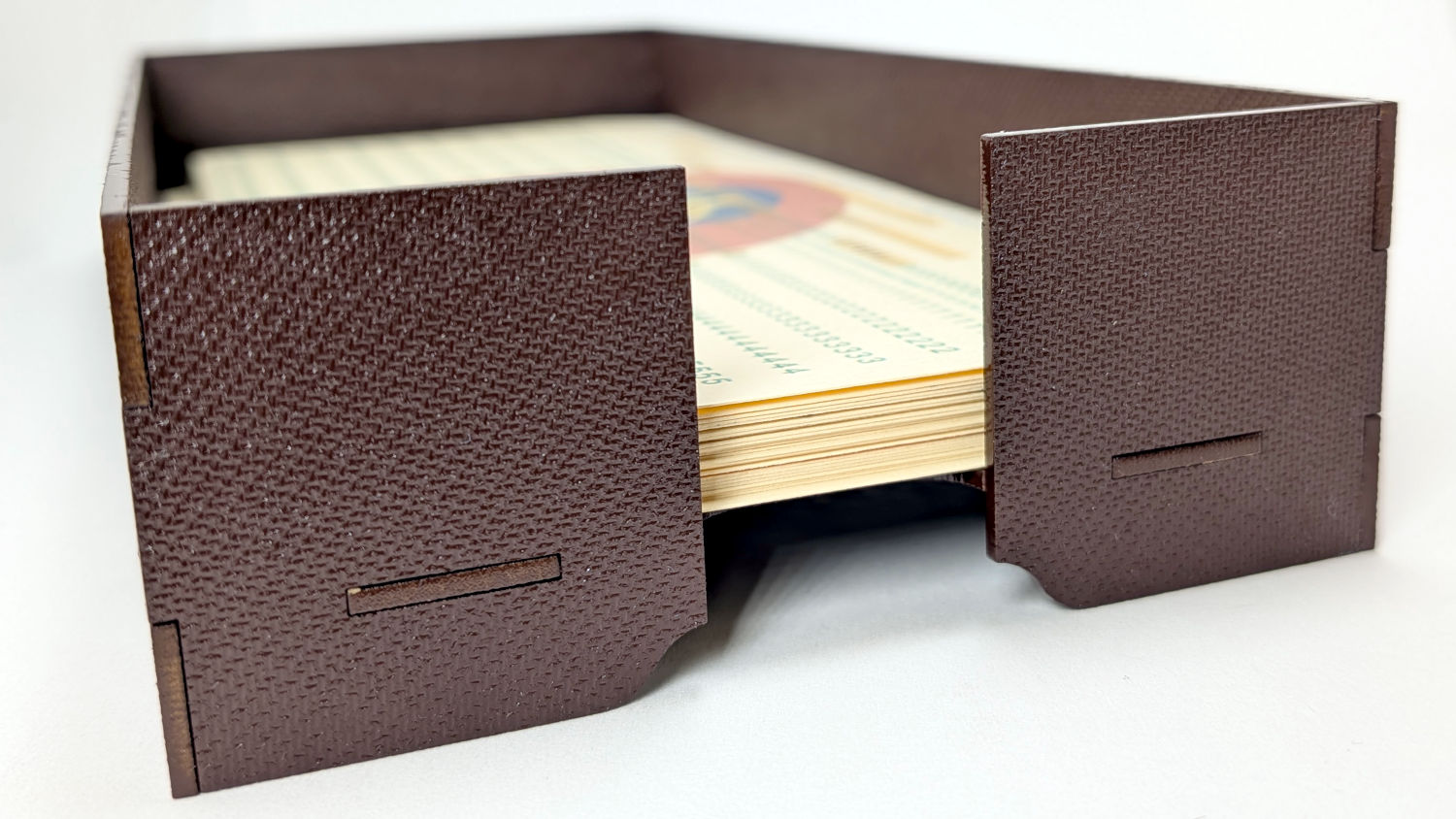
That’s a coat of Rustoleum Painter’s Touch 2x [many more adjectives] Kona Brown Gloss rattlecan paint atop Trocraft Eco board. I sprayed the separate parts on a sheet of newspaper, waited 20 minutes, flipped them over, sprayed the other side, gave them another 20 minutes, and got them inside out of the wind for a day of curing.
They’re held together by cyanoacrylate adhesive dots between the tabs, with accelerator daubed on the other side of the joint to encourage prompt curing. In general I do not like cyanoacrylate, but sometimes it seems like the right hammer for the job.
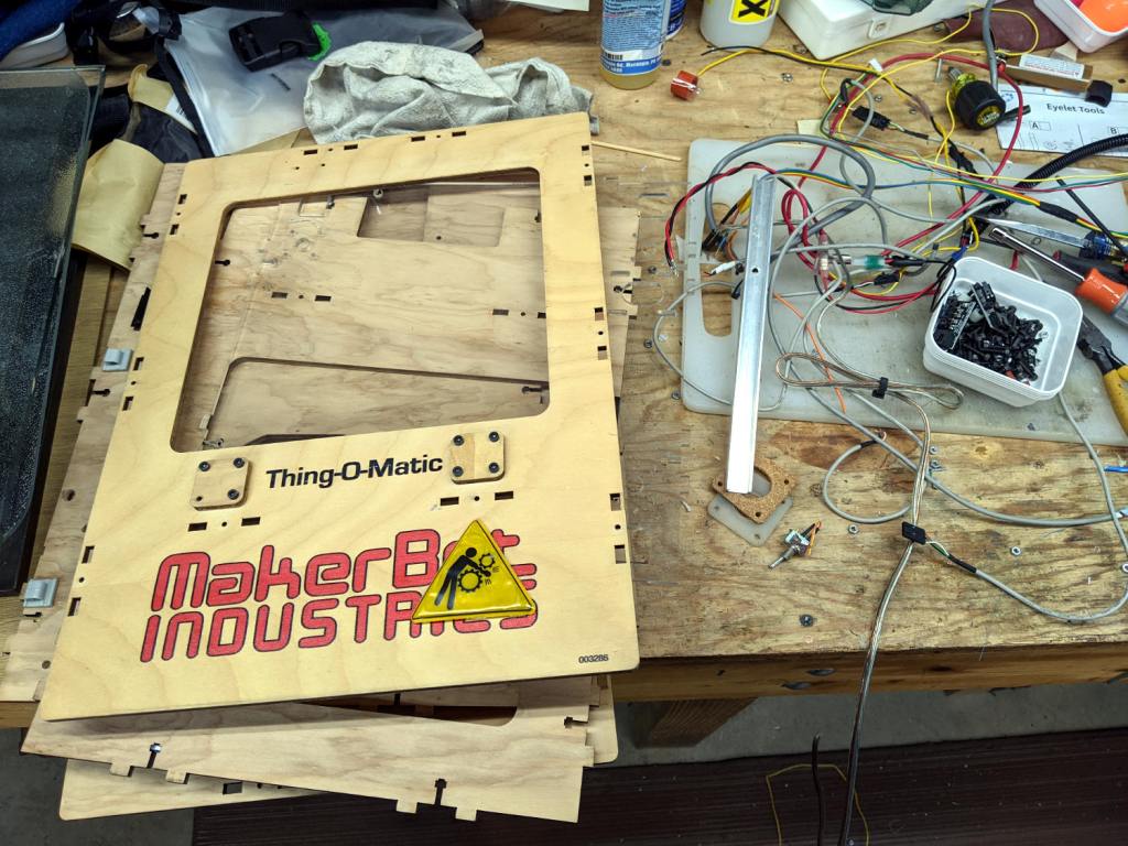
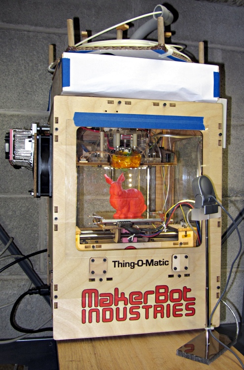
The Thing-O-Matic got me started in 3D printing (and blogging!), provided an education in many useful subjects, and has long since outlived its usefulness.
The recesses in cheap 1/4-inch shank nut drivers aren’t much deeper than the nuts, which means a screw sticking out of the nut by more than a few threads defeats the entire purpose.
Well, I can fix that:
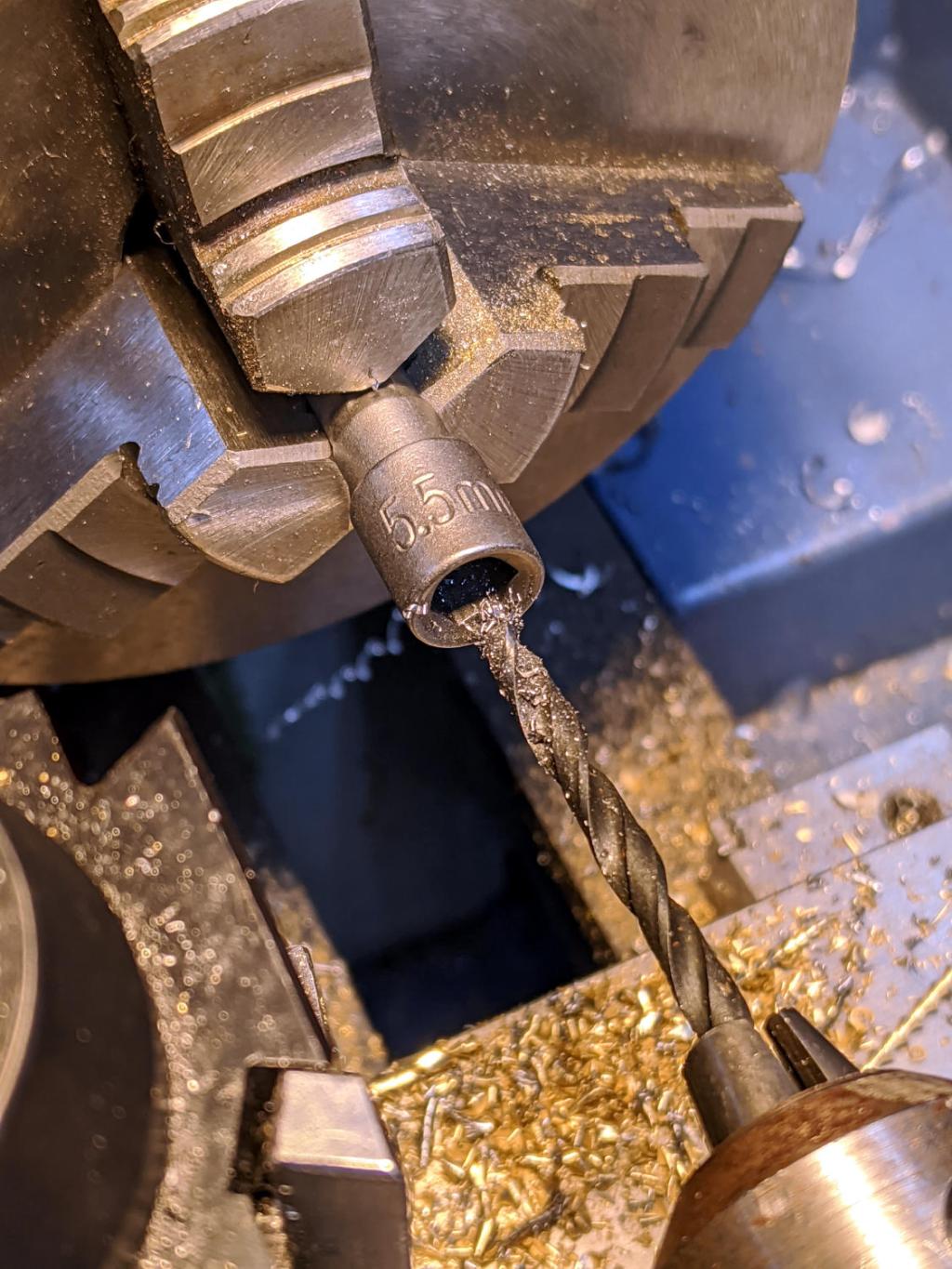
Drilling 5.5 mm socket
That’s a 5.5 mm socket for M3×0.5 machine screw nuts, getting a screw clearance hole drilled into it with a #28 drill (0.1405 inch = 3.5 mm). The sockets are allegedly “forged and hardened”, but an ordinary HSS drill bit cuts like they’re butter, so I’m thinking somebody skipped the hardening step.
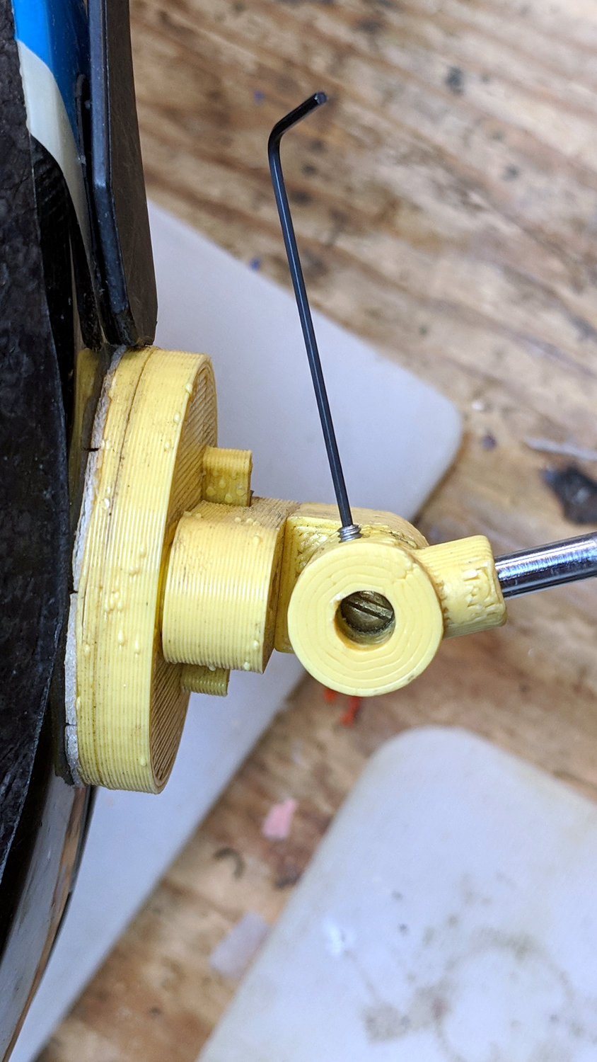
That’s a 0.035 inch = 35 mil hex wrench, of which Eks reminds me “Any time your design requires a tiny [obscene gerund] wrench, you’re doing it wrong”.
Ex post facto notes from the third Squidwrench Electronics Workshop.
Exhibit various 50 Ω resistors, including my all-time favorite, a 600 W 3 GHz dummy load:
600 W Dummy Load Resistor
… down to a 1/8 Ω metal film resistor.
The dummy load’s N connector triggered a regrettable digression into RF, belatedly squelched because I wasn’t prepared to extemporize on AC concepts like reactance which we haven’t covered yet.
Discussion of resistor applications, power handling, power derating with temperature, etc:
Whiteboard – Session 3 – Resistor power derating
Why you generally won’t find 50 Ω load resistors in Raspberry Pi circuits. Cartridge heaters for 3D printers, not aluminum power resistors, although everyone agrees they look great:
Power resistors on heat spreader
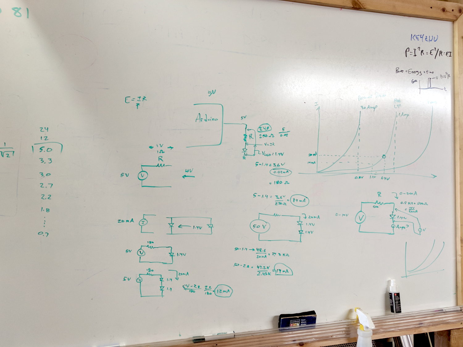
Discussion of voltage vs. current sources, why voltage sources want low internal resistances and current sources want high resistances. Bungled discussion of current sources by putting diodes in parallel; they should go in series to show how added voltage doesn’t change current (much!) in sources driven from higher voltages through higher resistances:
Whiteboard – Session 3 – Voltage vs Current Sources
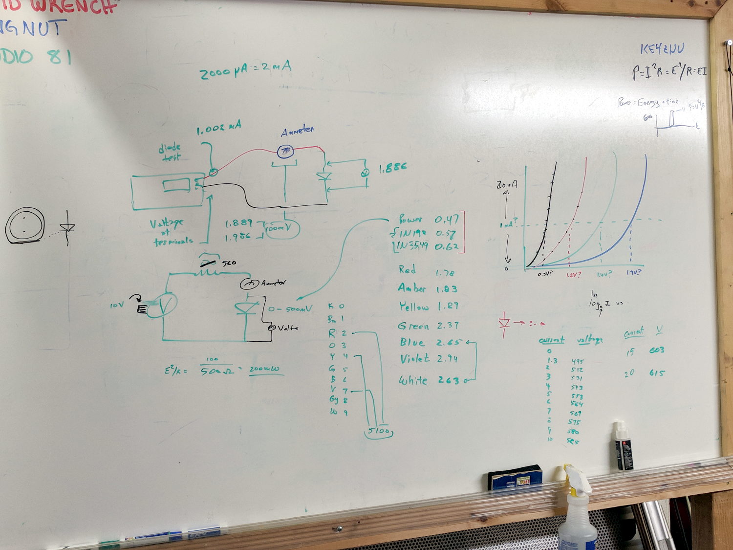
Use Siglent SDM3045X DMM in diode test mode to measure forward drop of power / signal / colored LEDs, discuss voltage variation with color / photon energy. Measure 1.000 mA test current for all forward voltages.
Compute series resistor (500 Ω) to convert adjustable power supply (the digital tattoo box, a lesson in itself) into reasonable current source; roughly 10 V → 20 mA. Find suitable resistor (560 Ω) in SqWr junk box parts assortment, digression into color band reading.
Wire circuit with meters to measure diode current (series!) and voltage (parallel!), measure same hulking power diode (after discovering insulating washers now in full effect) as before in 1 mA steps to 10 mA, then 15 and 20 mA, tabulate & plot results:
Whiteboard – Session 3 – Diode current vs forward drop
Discover warm resistor, compute power at 20 mA, introduce cautionary tales.
Lesson learned about never returning parts to inventory, with 560 Ω resistor appearing in diode drawer. Cautionary tales about having benchtop can of used parts as front-end cache for inventory backing store.