Following a linkie I can no longer find led me to retrieve the Tektronix Circuit Computer in my Box o’ Slide Rules:
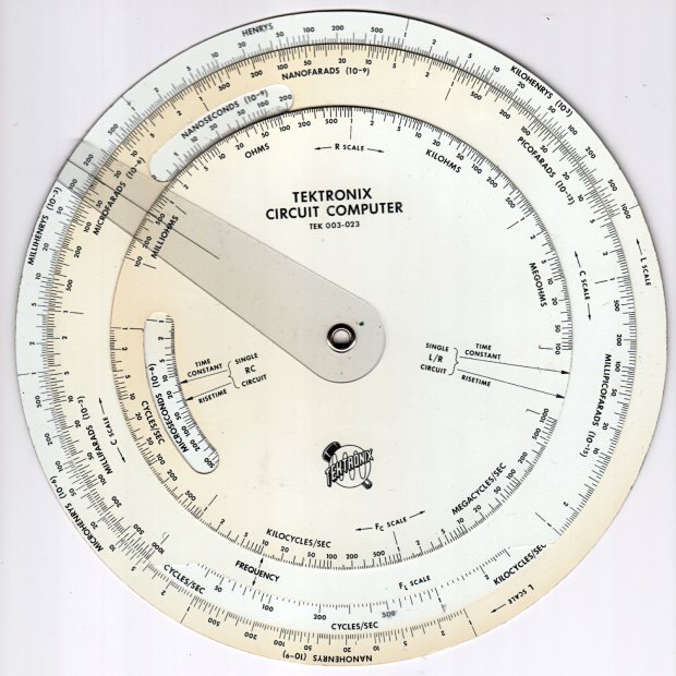
I’m pretty sure it came from Mad Phil’s collection. One can line up the discolored parts of the decks under their cutout windows to restore it to its previous alignment; most likely it sat at the end of a row of books (remember books?) on his reference shelf.
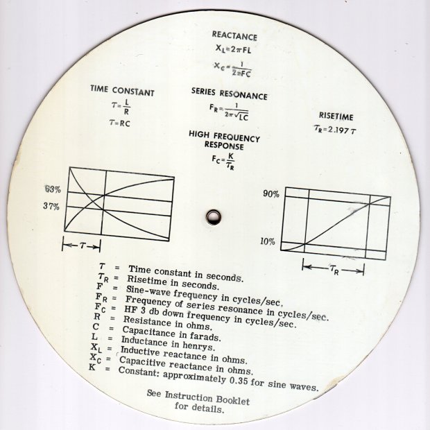
The reverse side lists the equations it can solve, plus pictorial help for the puzzled:
Some searching reveals the original version had three aluminum disks, shaped and milled and photo-printed, with a honkin’ hex nut holding the cursor in place. The one I have seems like laser-printed card stock between plastic laminating film; they don’t make ’em like that any more, either.
TEK PN 003-023 (the paper edition) runs about thirty bucks (modulo the occasional outlier) on eBay, so we’re not dealing in priceless antiquity here. The manual is readily available as a PDF, with photos in the back.
Some doodling produced key measurements:
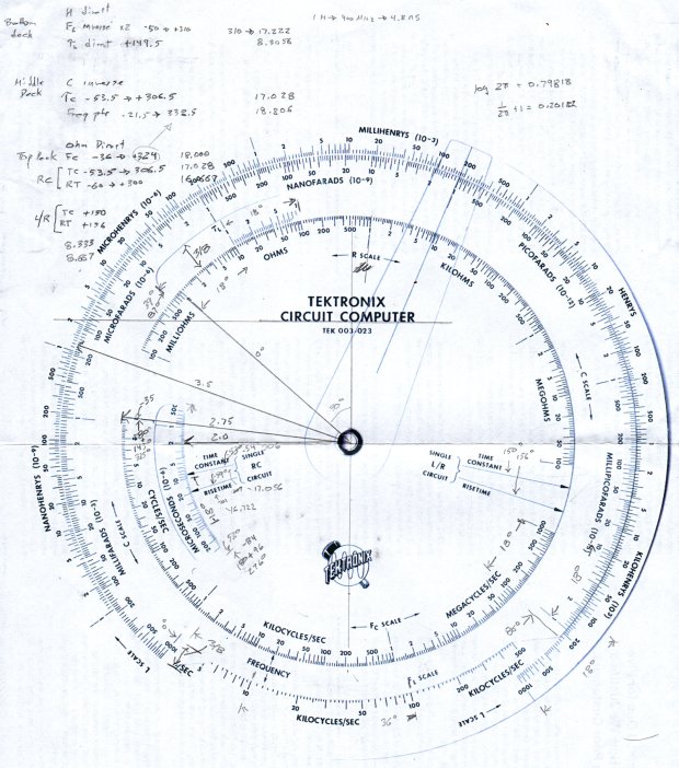
All the dimensions are hard inches, of course.
Each log decade spans 18°, with the Inductive Frequency scale at 36° for the square root required to calculate circuit resonance.
Generating the log scales requires handling all possible combinations of:
- Scales increase clockwise
- Scales increase counterclockwise
- Ticks point outward
- Ticks point inward
- Text reads from center
- Text reads from rim
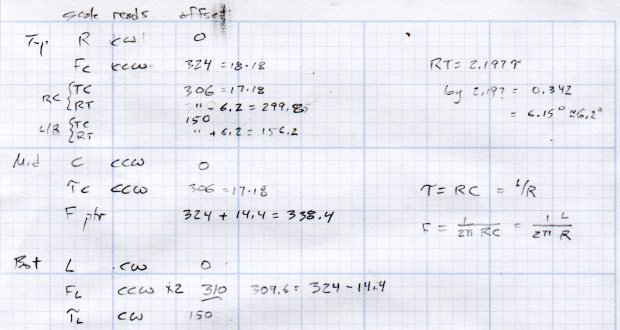
I used the 1×100 tick on the outer scale of each deck as the 0° reference for the other scales on that deck. The 0° tick appears at the far right of plots & engravings & suchlike.
The L/R Time Constant (tau = τ) pointer on the top deck and the corresponding τL scale on the bottom deck has (what seems like) an arbitrary -150° offset from the 0° reference.
The Inductive Frequency scale has an offset of 2π, the log of which is 0.79818 = 14.37°.
The risetime calculations have a factor of 2.197, offsetting those pointers from their corresponding τ pointer by 0.342 = log(2.197) = 6.15°.
A fair bit of effort produced a GCMC program creating a full-size check plot of the bottom deck on the MPCNC:

By the conservation of perversity, the image is rotated 90° to put the 1 H tick straight up.
The 3018 can’t handle a 7.75 inch = 196 mm disk, but a CD-size (120 mm OD) engraving came out OK on white plastic filled with black crayon:

The millimeter scale over on the right shows the letters stand a bit under 1 mm tall. And, yes, the middle scale should read upside-down.
Properly filling the engraved lines remains an ongoing experiment. More downforce on the diamond or more passes through the G-Code should produce deeper trenches, perhaps with correspondingly higher ridges along the sides. Sanding & polishing the plastic without removing the ink seems tedious.
The Great Dragorn of Kismet observes I have a gift for picking projects at the cutting edge of consumer demand.
More doodles while figuring the GCMC code produced a summary of the scale offsets:
Musings on the parameters of each scale:
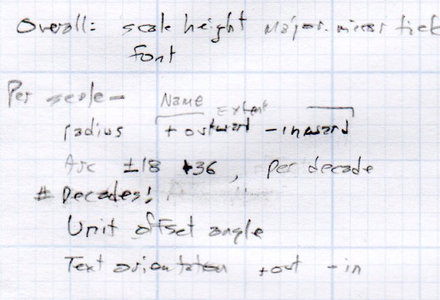
How to draw decades of tick marks:
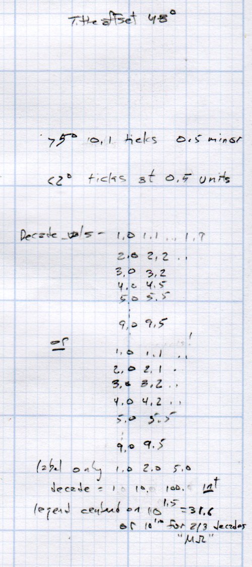
It turned out easier to build vectors of tick mark values and their corresponding lengths, with another list of ticks to be labeled, than to figure out how to automate those values.
More on all this to come …

Comments
13 responses to “Tektronix Circuit Computer: Layout Analysis”
I’ve gotten good marking on laser engraved acrylic by flooding with acrylic paint, letting dry, then knocking it off. It removes relatively easily and gives nice sharp contrast.
How much laser power do you need to engrave white(-ish) acrylic?
A slightly charred trench would definitely grab paint better than the slick V-groove from a diamond drag tool.
AFAICT, a 40 W CO2 laser is about the minimum for cutting acrylic. I keep lusting after a Lasersaur, but …
This project is reminiscent of a pilot’s E6B:
#ad https://amzn.to/2XBXOSM
That can be your next project!
If I were a pilot, it’d be even better!
Engraving 0.2 mm lines in aluminum poses a challenge I’m definitely not ready to tackle. [sigh]
[…] all that prepared, a full-size Tek Circuit Computer disk plots the way it should on a sheet of Letter-size […]
[…] Tektronix Circuit Computer scale annotations read both inward (from the center) and outward (from the […]
[…] Tektronix Circuit Computer needs text along radial […]
[…] Tektronix Circuit Computer, being a specialized circular slide rule, requires logarithmic scales bent around […]
[…] Nisley at The Smell of Molten Projects in the Morning blog writes about the Tektronix Circuit Computer. This is more like a circular slide rule than a true […]
[…] to cut laminated cardstock decks for the Homage Tektronix Circuit Computer required a bit more blade extension than my LM12UU holder made […]
[…] to see how it worked, I engraved the Tek Circuit Computer scales on scrap […]
[…] reproduction circular slide rule from the mid-1960s may not be the cutting edge of consumer demand, but the pen version of a Tektronix Circuit Computer […]
[…] judge from the dislodged pigment grains, the original Tektronix Circuit Computer probably used then-new laser printing on good-quality paper, laminated between plastic […]