Ed Nisley's Blog: Shop notes, electronics, firmware, machinery, 3D printing, laser cuttery, and curiosities. Contents: 100% human thinking, 0% AI slop.
Category: Software
General-purpose computers doing something specific
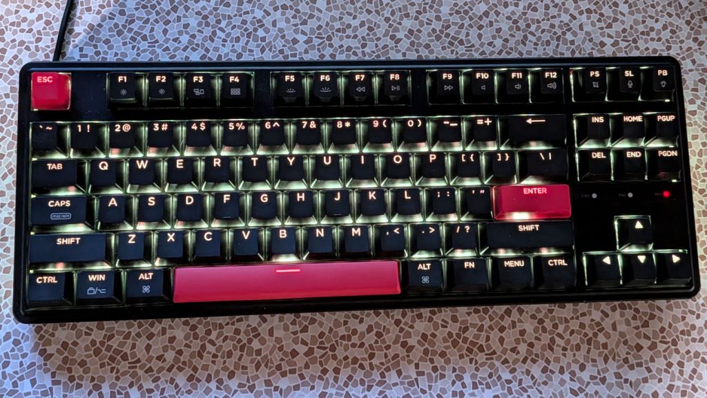
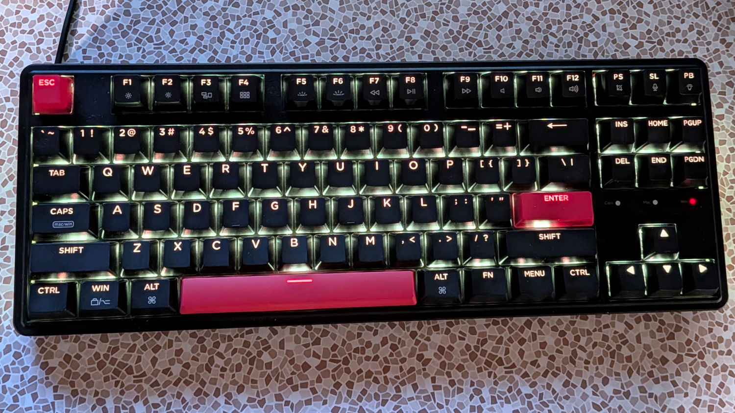
Having set the Moonlander to use Auto Shift, I’ve come to depend on it, so I got a Keychron C3 Pro keyboard for one of the Basement Shop’s PCs because it glows in the dark and can be configured with QMK:
Keychron C3 Pro – tamed
The default setup has rainbow hues cycling across the keyboard, which I find entirely too distracting. Although you can manually select the solid-color variant from the myriad possibilities using the keyboard, I forced a solid color with this config.h file:
#define RGB_MATRIX_DEFAULT_ON true // Sets the default enabled state, if none has been set
#define RGB_MATRIX_DEFAULT_MODE RGB_MATRIX_SOLID_COLOR // Sets the default mode, if none has been set
#define RGB_MATRIX_DEFAULT_HUE 36  // Sets the default hue value, if none has been set
#define RGB_MATRIX_DEFAULT_SAT 255 // Sets the default saturation value, if none has been set
#define RGB_MATRIX_DEFAULT_VAL 255 // Sets the default brightness value, if none has been set
Enabling Auto Shift requires this rules.mk file:
AUTO_SHIFT_ENABLE = yes
Both of those go in the keymap directory defining the keyboard mapping for my custom setup:
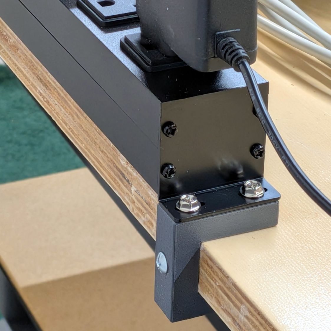
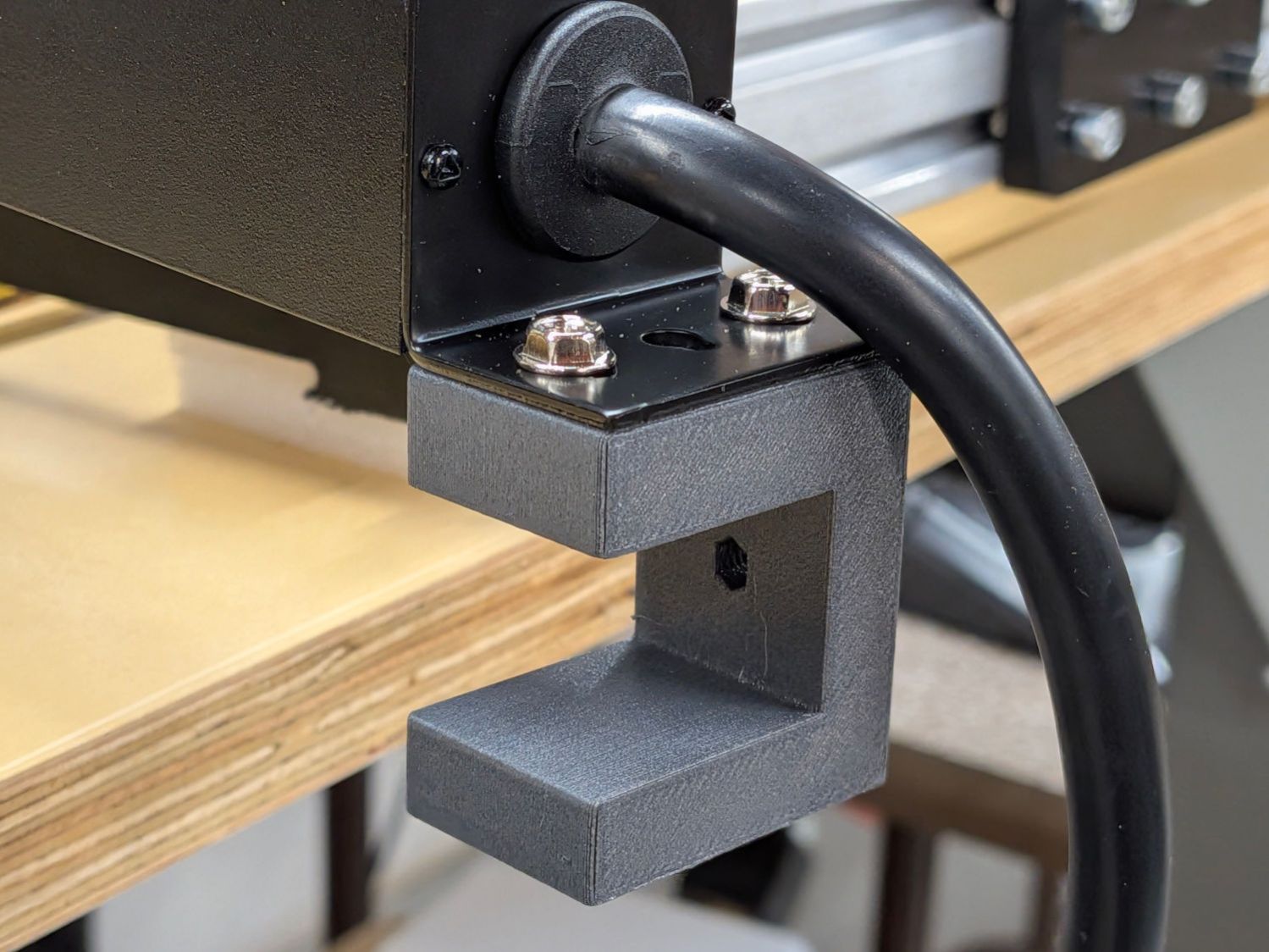
A spate of tidying-up led to mounting an outlet strip along the back of a bench:
Outlet Bench Mount – installed
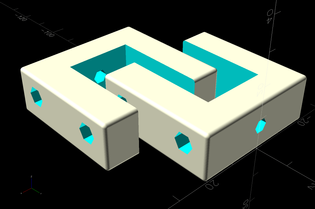
Rather than drill holes into the top of the bench for those screws, they fit into M4 brass inserts heat-staked into the brackets:
Outlet Bench Mount – show view
The holes for those inserts aren’t centered side-to-side on the brackets, because the screw holes aren’t centered on the bent-steel angles forming the outlet strip endplates.
The bottom arm on the brackets probably isn’t necessary, but they kept the outlet strip from crawling away while I match-drilled two holes for the screws into the side of the benchtop.
For obvious reasons, the brackets print on their sides:
Outlet Bench Mount – build view
Another outlet strip from a different manufacturer is, of course, different, but changing three parameters in the OpenSCAD program summons a different bracket from the vasty digital deep:
Outlet Bench Mount – different brand
Parametric modeling and a 3D printer are exactly the right hammers for the job …
This file contains hidden or bidirectional Unicode text that may be interpreted or compiled differently than what appears below. To review, open the file in an editor that reveals hidden Unicode characters.
Learn more about bidirectional Unicode characters
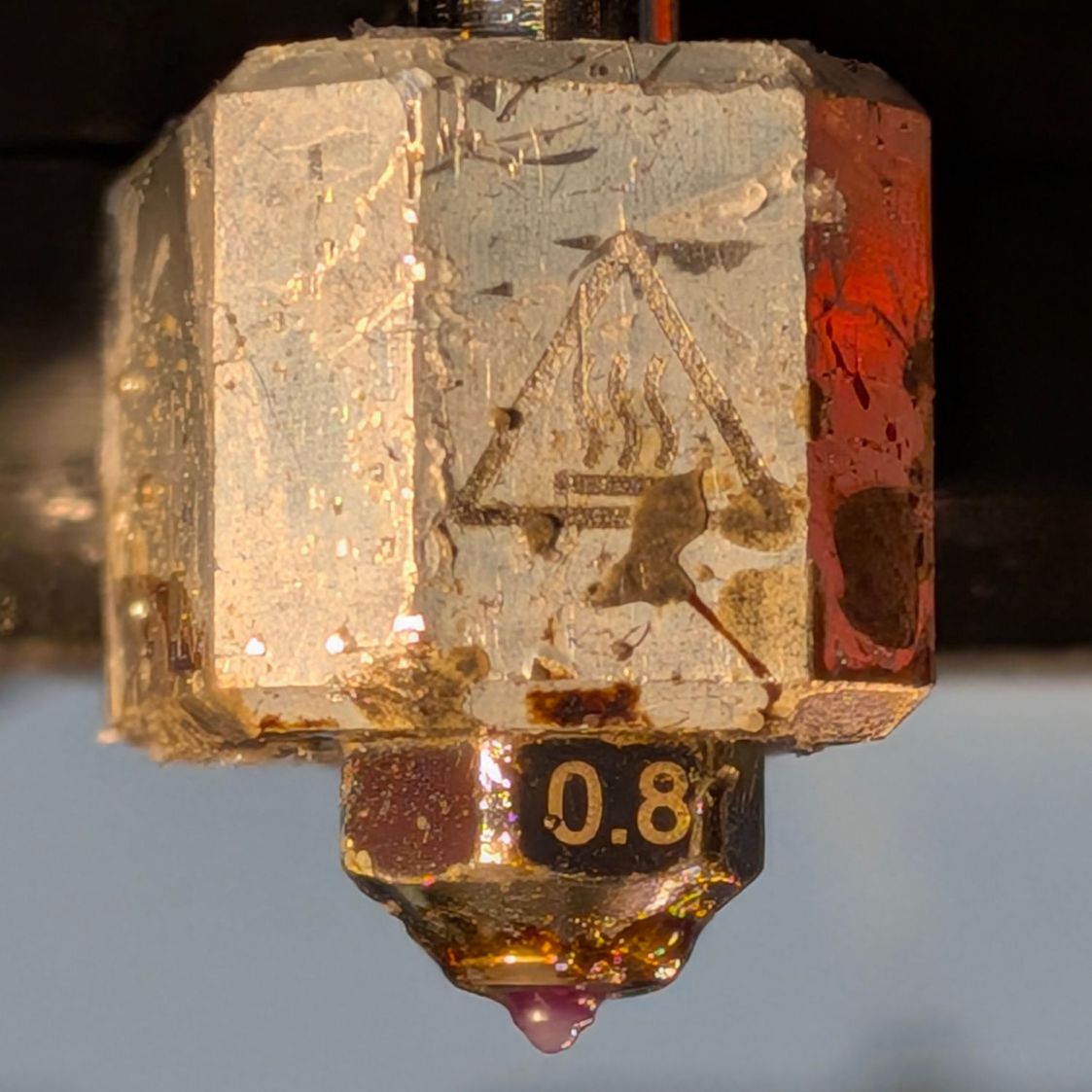
The aluminum block doesn’t look nearly as awful as these pictures suggest; those plastic smears serve as reminders of a few previous printing mishaps.
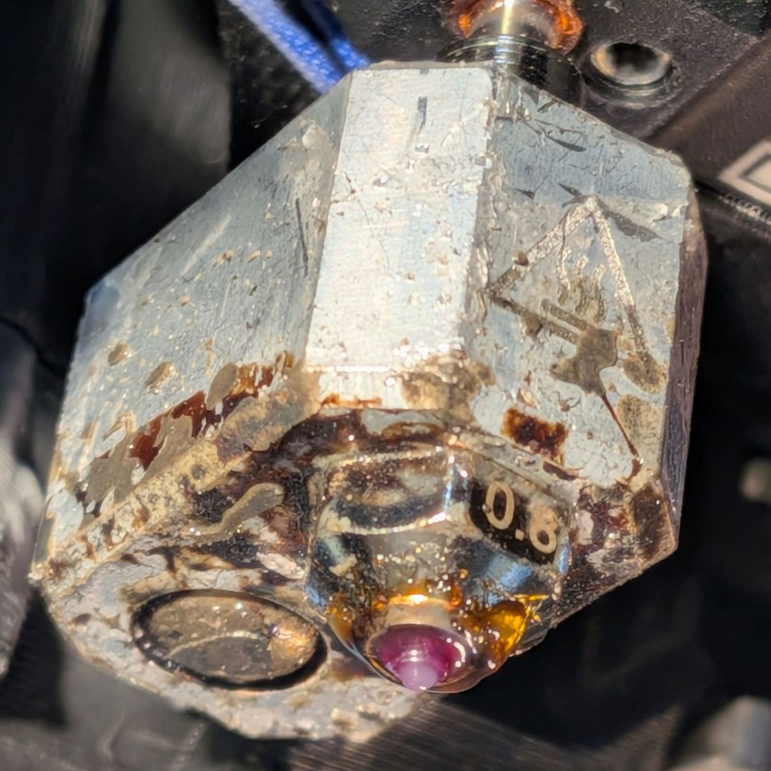
The nozzle is a 0.8 mm Durozzle with a ruby tip suitable for abrasive filaments like PETG-CF, although this is gooey squishy “natural” TPU:
Prusa MK4 hot end – 0.8 mm Durozzle ruby – bottom
The first patio table foot test piece in TPU had terrible adhesion to the Textured Sheet, which I eventually tracked down to an excessively thick first layer. Given that the MK4 homes the axes and performs mesh bed leveling probes over the build area, this was difficult to believe, particularly because it had never been a problem with the Prusa 0.4 mm ObXidian hardened steel nozzle.
More poking around showed some of the plastic drool left on the outside of the nozzle from the previous print session (as shown in the two pictures above) could remain hardened or at least “not squishy” despite the nozzle being heated before homing and mesh probing. Because probing depends on having the nozzle touch the platform, anything between the nozzle and the steel sheet will raise the Z=0 position and cause all the layers to be too high.
As far as I can tell, ruby has a thermal coefficient around 40 W/m·K, roughly the same as steel. Both are considerably lower than the 200-ish W/m·K for the aluminum block surrounding the nozzle tube, suggesting most of whatever temperature gradient there may be occurs between the heater and the nozzle, not in the nozzle.
While puzzling that out, I noticed the nozzle heated to only 160 °C prior to homing and probing, which seemed low for a filament calling for 230 to 250 °C during printing. Ordinary PETG heated to 170 °C, so something was different.
More puzzling showed the Start G-Code section of the printer’s Custom G-Code sets the home / probe temperature, herein reformatted for readability:
I had set up the eSun TPU 95A filament parameters based on Prusa’s TPU definition. I eventually discovered that definition includes the text MBL160 in its Notes section, which satisfies the regex in the first ternary operator:
Which sets the temperature to 10 °C below the first layer temperature, which I had set to 230 °C, so the probing now occurs at 220 °C.
I am not making this up.
Although that may be a bit too hot, the drool on the nozzle softens nicely and smashes flat during probing, thus solving the immediate problem and, without further ado, produced good round and square TPU feet.
Both the round and square TPU patio table feet came from a 0.8 mm nozzle on the Prusa MK4, which produces results much faster than the venerable Makergear M2’s 0.35 mm nozzle. However, for unknown reasons a 0.8 mm nozzle is not compatible with the MMU3, so changing from and to the default 0.4 mm nozzle requires a somewhat complex ritual.
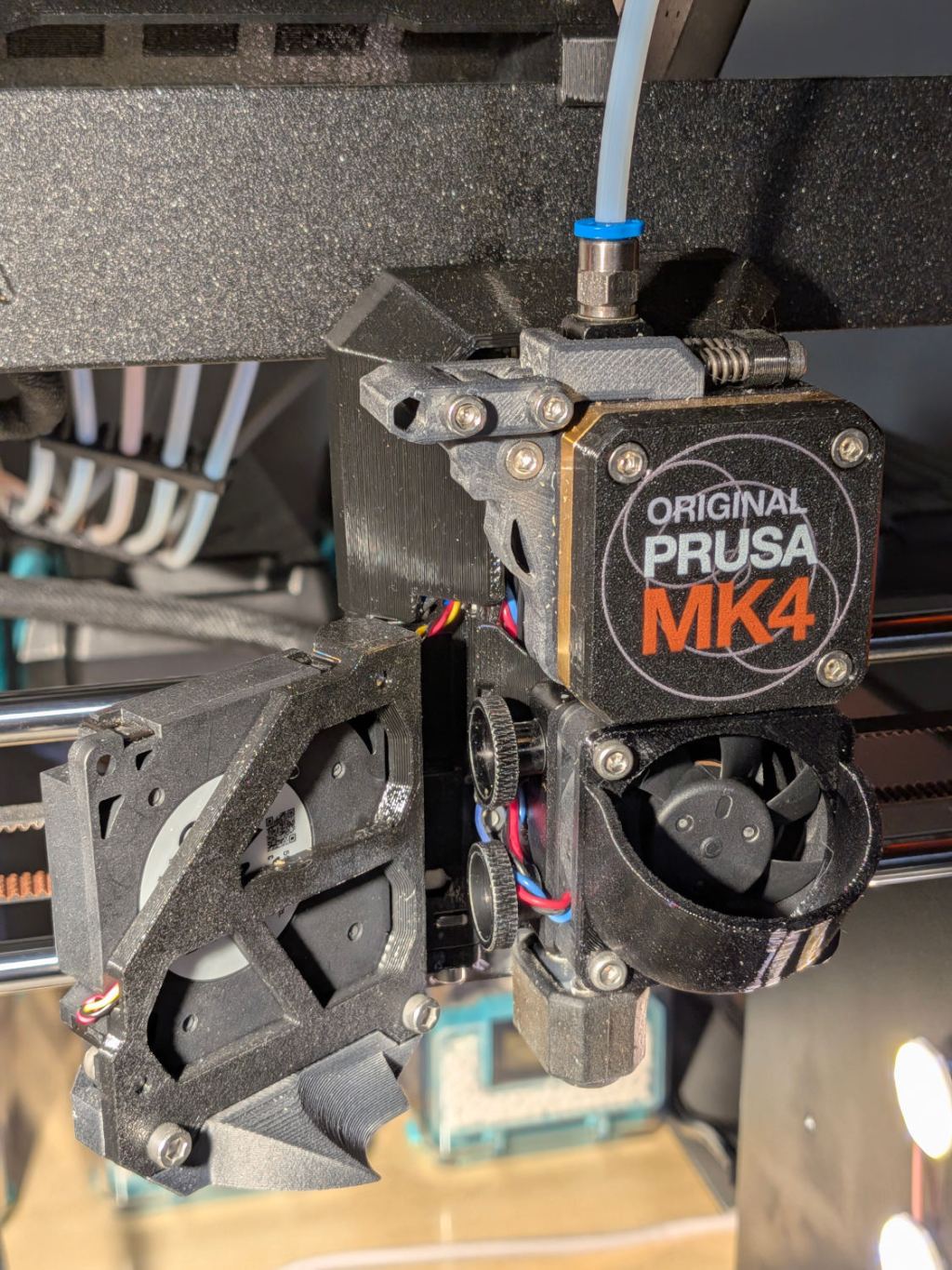
For context, the MK4 extruder and hot end:
Prusa MK4 – extruder overview
Because the MK4 automatically unloads the filament from the extruder (with help from auto-retracting filament spools) when using the MMU, the hot end doesn’t have any filament in it. Disconnect the PTFE tube from the fitting atop the extruder, insert the end of the TPU filament from its Polydryer box, and …
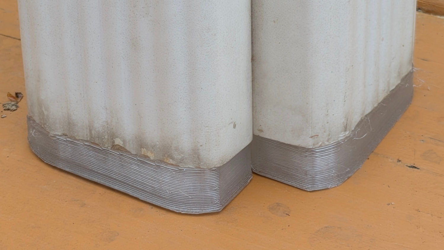
For a square patio table (with one missing foot), of course:
Patio Table Feet – installed
These are chunky enough to demonstrate they’re made of clear-ish TPU, at least when backlit:
Patio Table Feet – installed – backlit
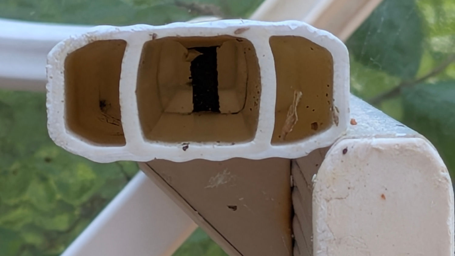
The interior of the leg determines what fits into it:
Patio Table Feet – leg interior
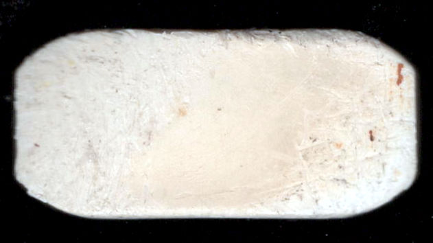
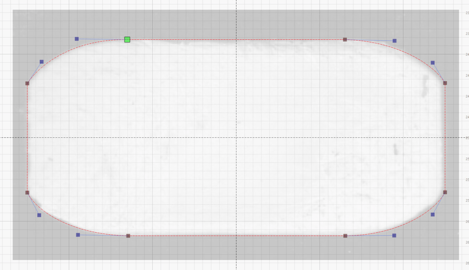
I pried out another foot, scanned it, and blew out the contrast:
Patio Table Foot – scan
Importing that into LightBurn let me draw a rectangle matching the measured size, then node-edit the corners to approximate the shape:
Patio Table Foot – LightBurn layout
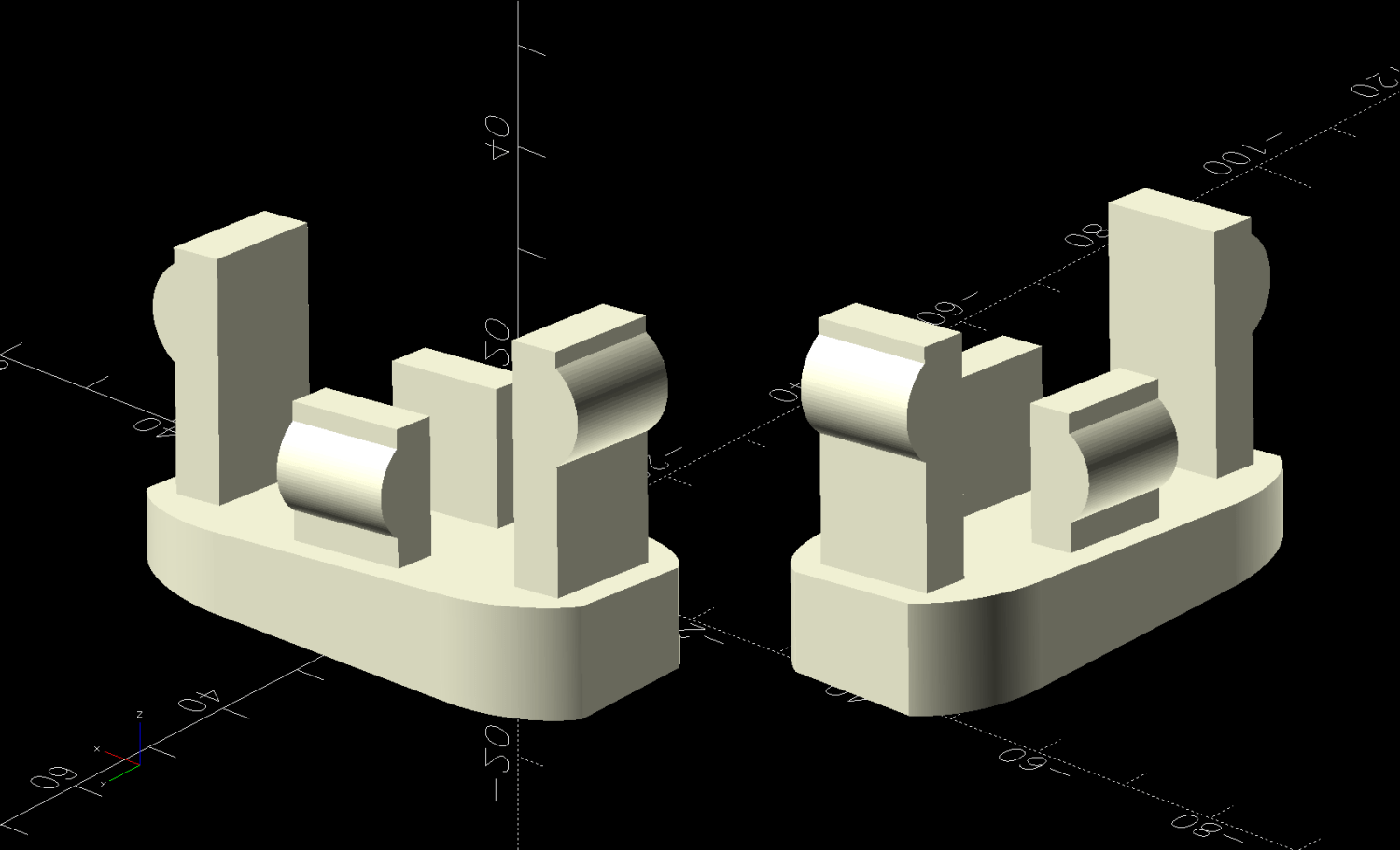
Export that shape as an SVG, import into OpenSCAD, and turn it into a solid model:
Patio Table Foot – solid model – show view
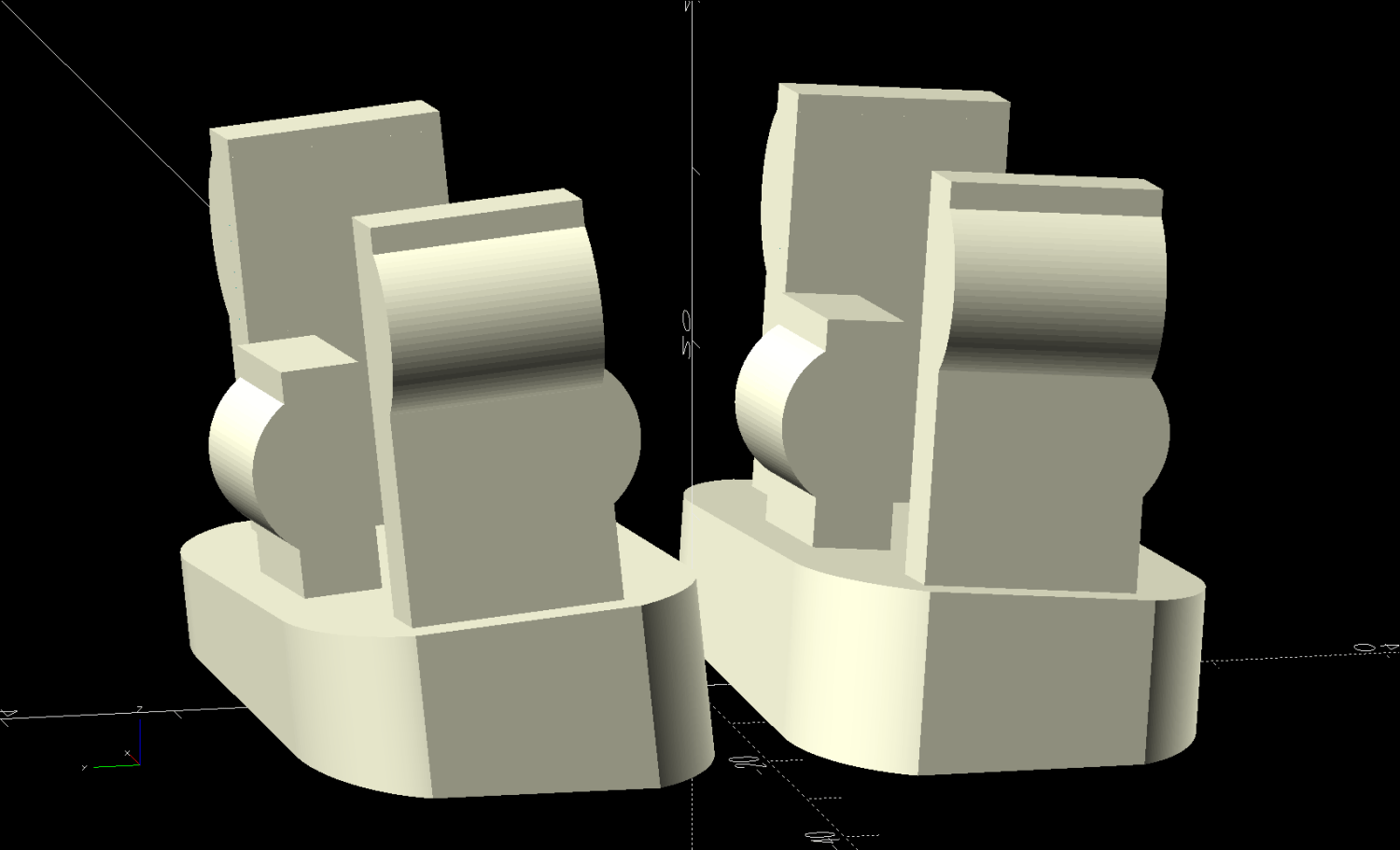
That’s the Show view simulating the actual positions, which demonstrates why the pair of legs at each corner wear mirror-imaged feet. The Build view arranges the pair more sensibly for 3D printing:
Patio Table Foot – solid model – build view
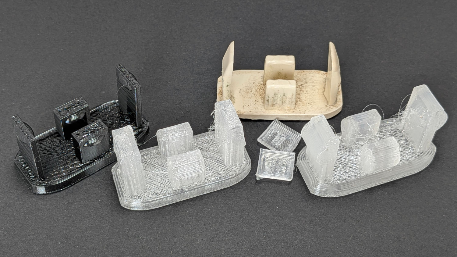
The protrusions and their bumps went through several iterations on the way to being functional, with the black TPU prototype on the left being entirely too bendy and the first clear version requiring utility knife editing to fit the end posts inside the leg:
Patio Table Feet – prototypes
The original feet seem to be injection-molded ABS with a flat bottom intended to erode one corner against whatever the table stands on. However, the legs splay out at 5° from the vertical, which makes the flat bottom I used for the first few iterations obviously wrong:
Patio Table Feet – flat foot
Somebody who can math harder than I would resolve the two angles and all the measurements into a single transformation matrix, but I rotated the foot separately around the X and Y axes, trigged the lowest corner to the proper height, then chopped off everything below Z=0. Works for me.
This file contains hidden or bidirectional Unicode text that may be interpreted or compiled differently than what appears below. To review, open the file in an editor that reveals hidden Unicode characters.
Learn more about bidirectional Unicode characters
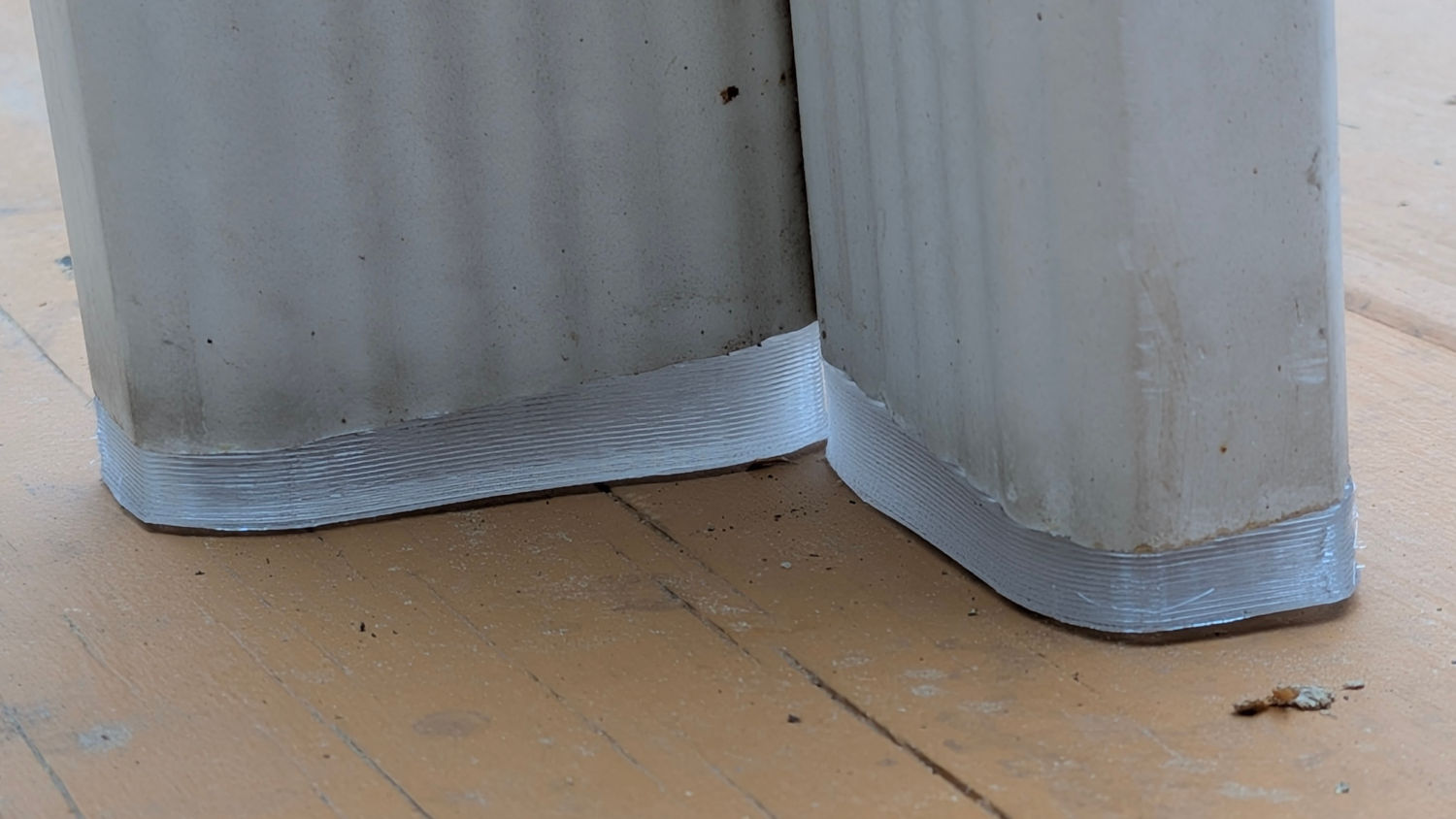
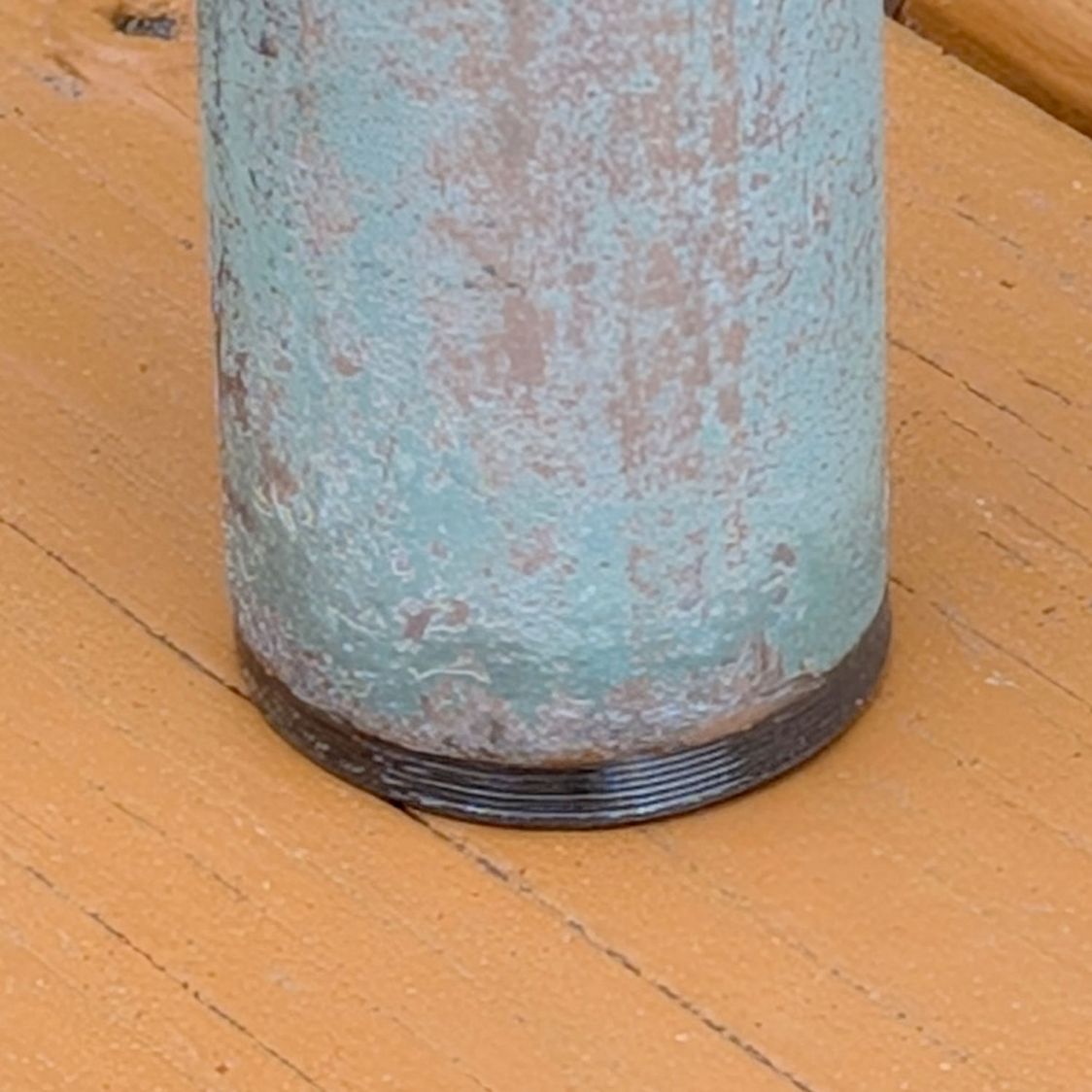
For a round patio table, although you can’t tell from the picture:
Round patio table feet – installed
Also despite appearances, that’s 3D printed from clear-ish TPU, with its black appearance due to internal reflections from the leg’s dark interior.
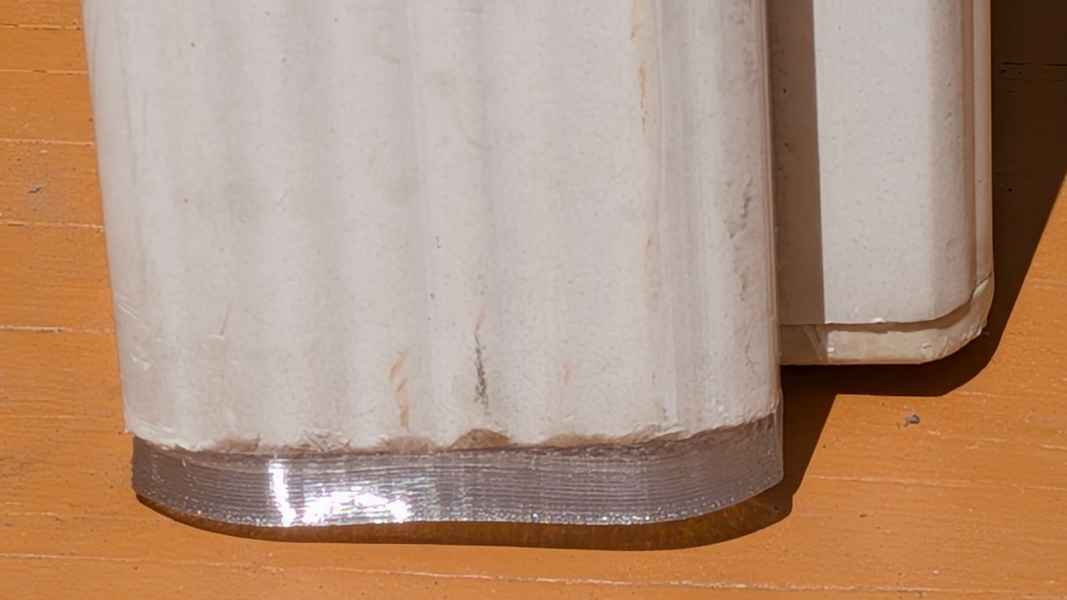
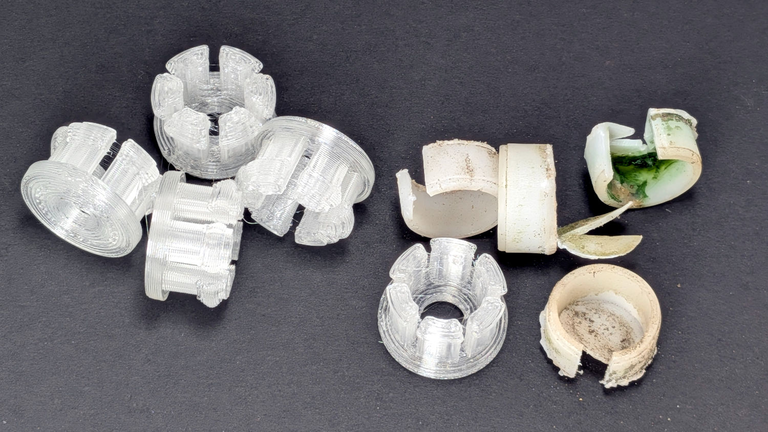
The original hard-white-plastic feet had eroded enough to let the aluminum legs scrape the deck paint:
Round patio table feet – old vs new
The only way to extract each old foot was to hack out a segment with a razor knife, after which it slid out easily.
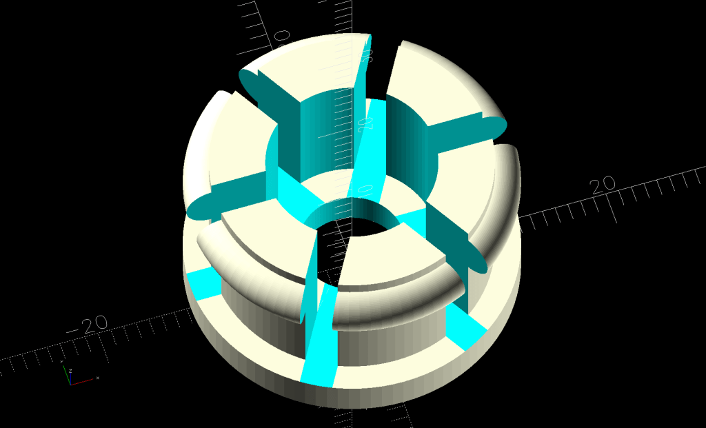
The ring around the top of the sections provides enough griptivity inside the leg to hold the foot in place:
Round Patio Table Foot – solid model
As with the TPU chains on the bike rack tray holder, I expect the compressed / bent segments will gradually relax inside the legs, but the feet ought not fall out in normal use.
The OpenSCAD source code isn’t quite a one-liner, but it’s close:
// Patio Table Foot - round legs
// Ed Nisley - KE4ZNU
// 2026-05-29

include <BOSL2/std.scad>

/* [Hidden] */

ID = 0;
OD = 1;
LENGTH = 2;

HoleWindage = 0.2;
Protrusion = 0.01;
NumSides = 4*3*2*4;
Gap = 5.0;

$fn=NumSides;

PadOA = [8.0,1*INCH,3.0];

SleeveOA = [13.0,21.7 - HoleWindage,12.0];

Kerf = 2.5;


//-----
// Build it

difference() {
  union() {
    tube(PadOA[LENGTH],od=PadOA[OD],id=PadOA[ID],anchor=BOTTOM) position(TOP)
      tube(SleeveOA[LENGTH],od=SleeveOA[OD],id=SleeveOA[ID],anchor=BOTTOM);
    up(PadOA[LENGTH] + SleeveOA[LENGTH] - 1.0)
      torus(d_maj=SleeveOA[OD],r_min=(PadOA[OD] - SleeveOA[OD])/2,anchor=TOP);
  }
  up(PadOA[LENGTH])
    for (a = [0,60,120])
      zrot(a)
        cuboid([PadOA[OD],Kerf,2*SleeveOA[LENGTH]],anchor=BOTTOM);
}
Except for having the bungee cord run across the middle of the tray where it blocks access for larger trays and tends to bend the taller leaves.
Well, I can fix that:
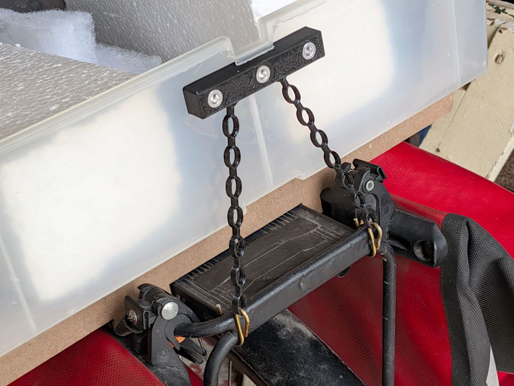
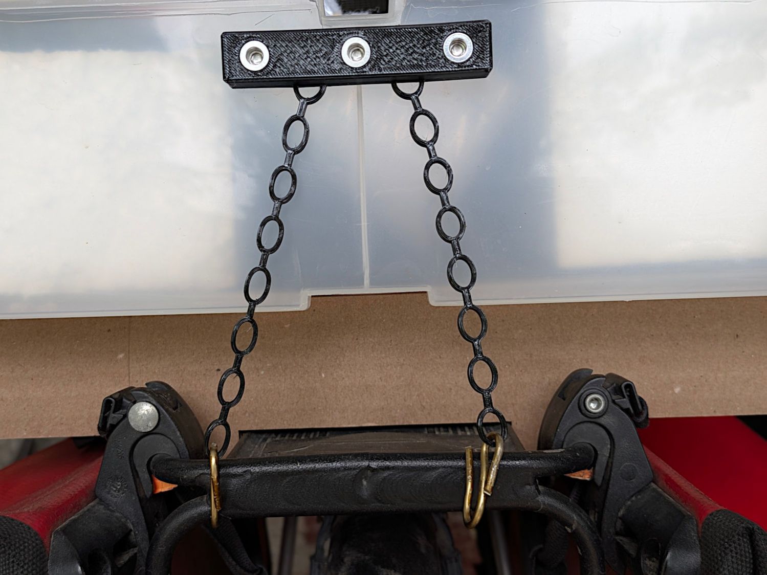
Bike Rack Tray Holder – straps – rear
The front tiedown is similar:
Bike Rack Tray Holder – straps – front
They’re printed from TPU: rectangular blocks and chains, ending in wire hooks bashed from a coat hanger. The M4 button-head screws thread into (uncrushed) rivnuts, which seemed easier to manage than square nuts in this situation.
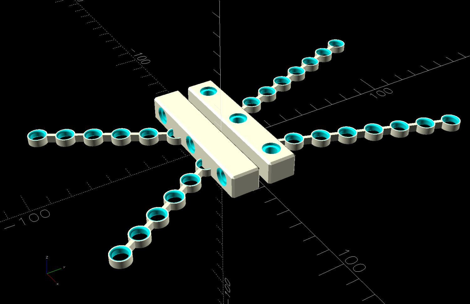
The chains are just thick circles, with half of the top links sunk into the blocks:
Stretchy Straps – build layout
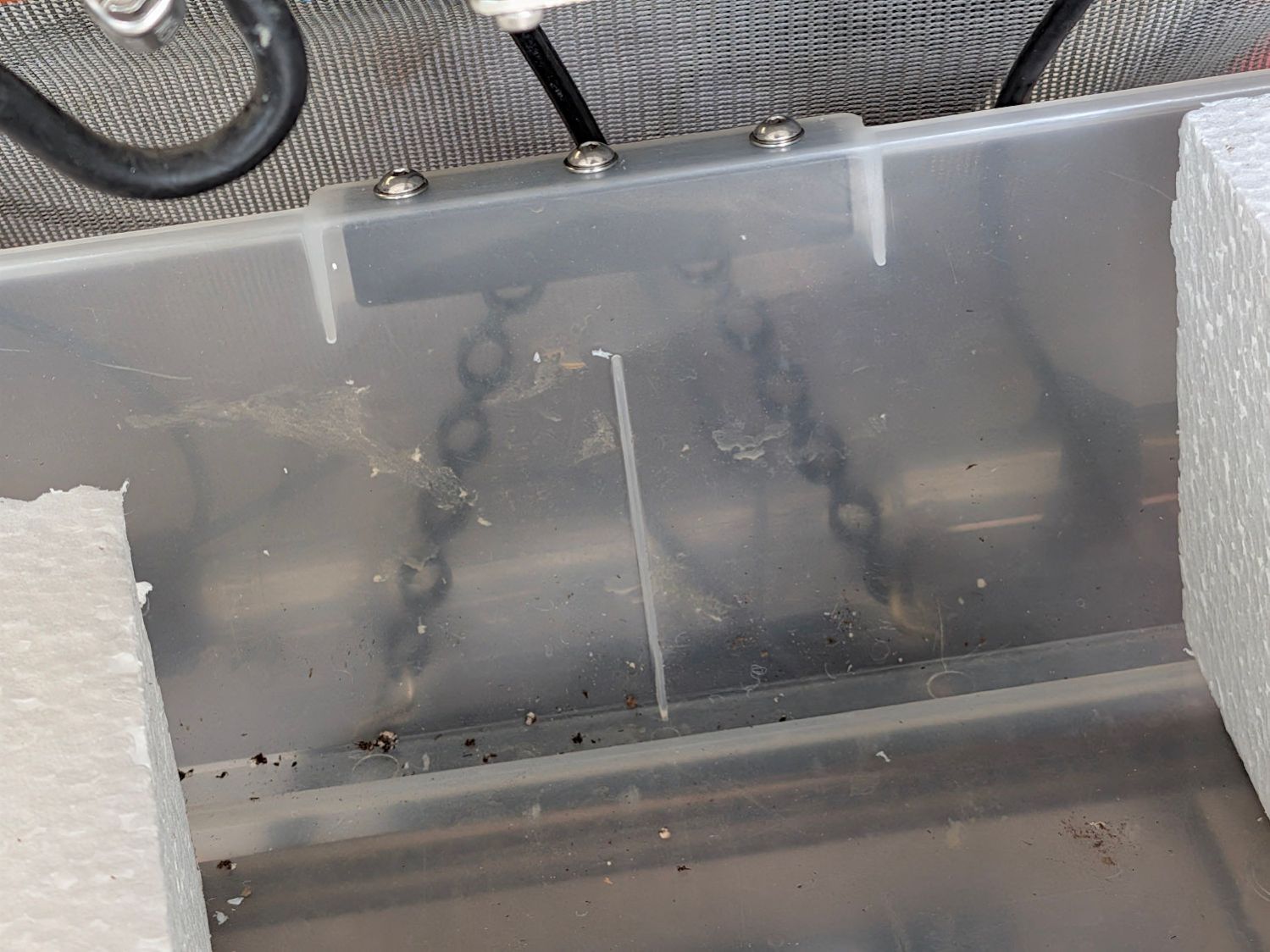
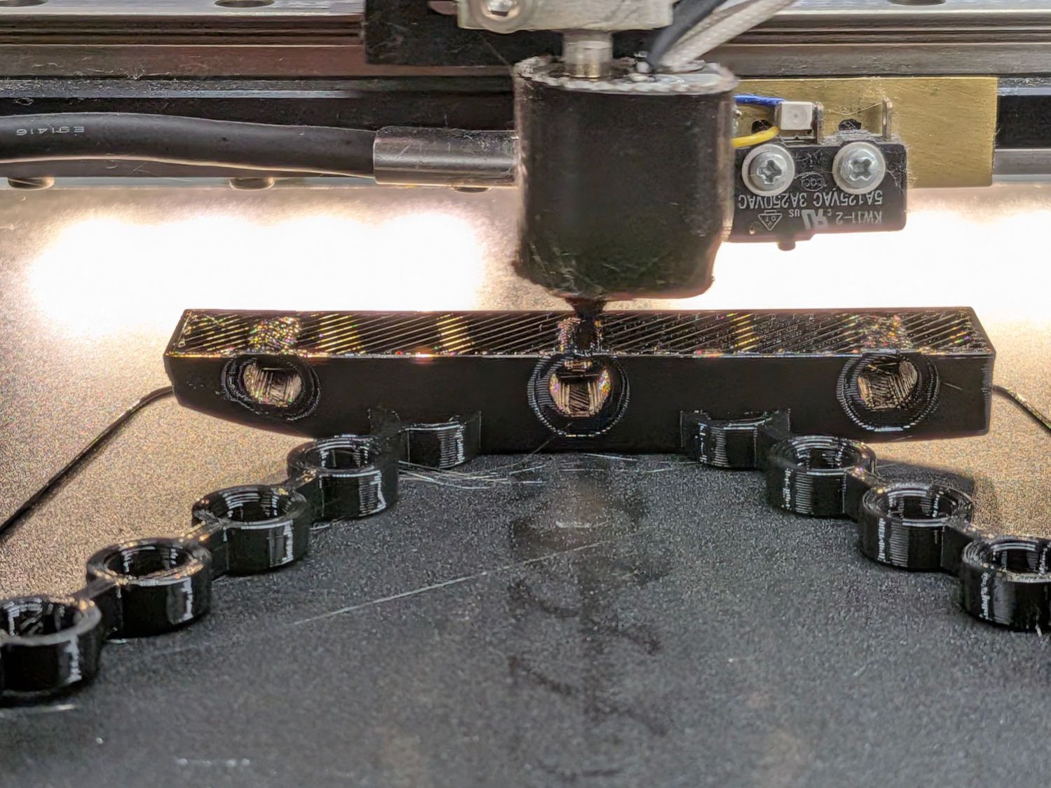
You’d (well, I’d) want to build them one at a time, because sometimes this happens:
Bike Rack Tray Holder – bad platform adhesion
Based on those measurements, I raised the extruder by 0.1 mm, but apparently did a poor job of cleaning / flattening the cold TPU on the nozzle and got it wrong. As a result, the first layer didn’t get squooshed properly onto the BuildTak, came unstuck, and produced art . The track down the middle of the photo shows traces of a previous, badly over-squooshed test chain.
The stretched TPU relaxes enough to leave very little tension after a day, as shown by the unhooked right chain:
Bike Rack Tray Holder – straps – relaxing
However, that make the chains exactly the right length, so they require even more force to get the hooks off the rack. After relaxing for another day, the stretched chains return to roughly their original lengths, so it’s all good.
This file contains hidden or bidirectional Unicode text that may be interpreted or compiled differently than what appears below. To review, open the file in an editor that reveals hidden Unicode characters.
Learn more about bidirectional Unicode characters