Ed Nisley's Blog: Shop notes, electronics, firmware, machinery, 3D printing, laser cuttery, and curiosities. Contents: 100% human thinking, 0% AI slop.
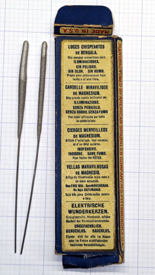
The back of the box gets downright multilingual, although there’s no English-language mention of “magnesium” anywhere on the box:
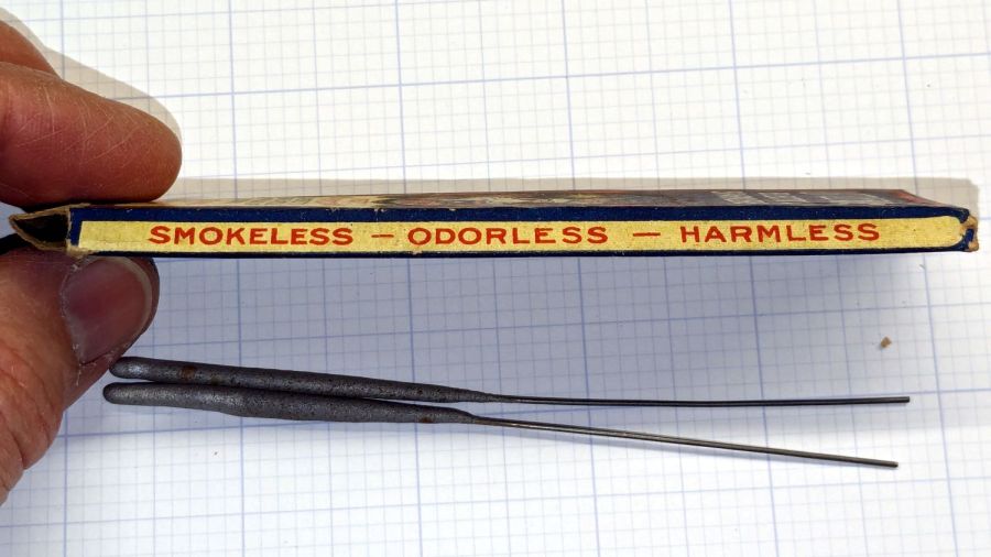
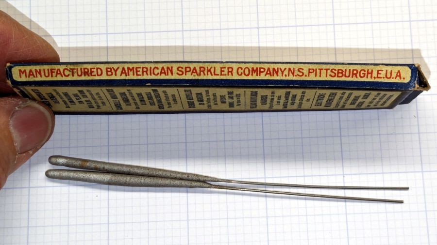
Little Fairy Electric Sparklers – box backLittle Fairy Electric Sparklers – box rightLittle Fairy Electric Sparklers – box left
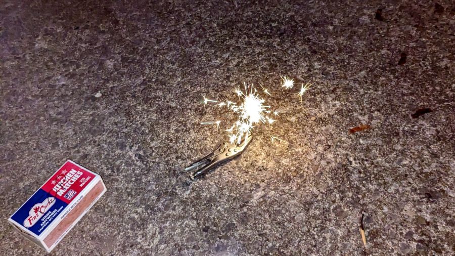
They are most assuredly not electric, which means they have no batteries to corrode and they still work fine:
Little Fairy Electric Sparklers – test firing
They emerged from a box of my father’s memorabilia, most likely packed away by his parents, so they date back to the early part of the previous century. The American Sparkler Company is long defunct, but the Internet never forgets.
Even my simple discrete LM3909 circuit can blink a blue LED from a battery producing under 1 V, but those cells were flat dead. Gotta look over there more often, I suppose.
In round numbers, the total capacity declined from 3.25 W·hr to 2.5 W·hr, which means a single battery can’t quite power the camera for the duration of our normal hour-long rides. I do not know what voltage trips the camera’s decision, but the batteries definitely shut down sooner.
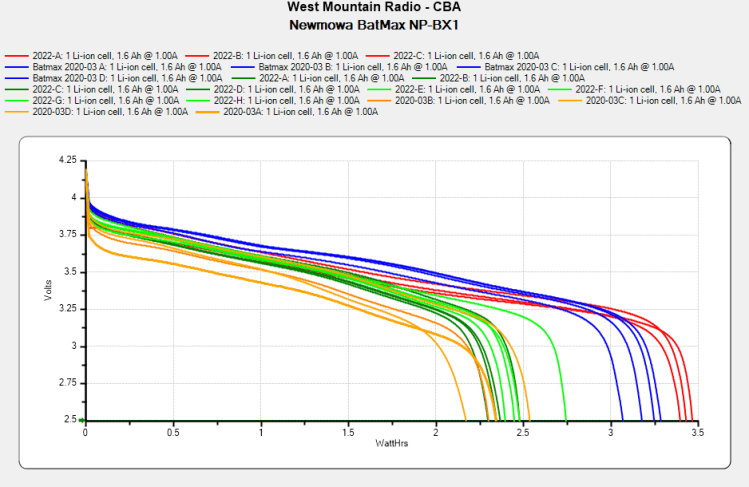
So, based on their previous track record, I bought another quartet of Batmax batteries. Being that type of guy, I tested both the old (2020) and new (2022) sets:
NP-BX1 – BatMax 2022 vs 2020 – used-new
The blue traces are the C/D batteries from the as-new tests back in early 2020, the green traces are C/D after two years of use, and the red traces are the “new” quartet after their first charge in the Official BatMax Charger.
It looks very much like BatMax is selling used batteries repackaged as new items, because they are indistinguishable from my used ones. They definitely are not the “Premium Grade A cells” touted in the description.
I returned them for a refund and sent the test results to BatMax; they sent “new replacements” even though I said I would not pay for any future shipments. The batteries had a slightly different wrapper, but the test results were still indistinguishable from used batteries. I offered to return the package and was told that would not be needed.
It seems three good batteries now cost about as much as four crap batteries, under the reasonable assumption chargers are essentially free.
Three batteries isn’t quite enough for my usual rotation and, for unknown reasons, one cannot buy only batteries, so in short order I will have two chargers and six batteries.
The consolidated test results:
NP-BX1 – Newmowa Batmax 2022 comparison
The color code:
Newmowa: red
BatMax 2020 new: blue
BatMax 2020 used: orange
BatMax 2022 new: green + lime
I stopped writing Amazon reviews after having a few detailed-writeups-with-graphs rejected for the usual unspecified reasons. As the Finn put it, “You wanna download, you know the access code already.”
Dropping the ordinary flashlight bulb into the drawer where it belonged revealed what I think is a halogen flashlight bulb, so I rebuilt the blinky test setup:
Halogen flashlight bulb test setup
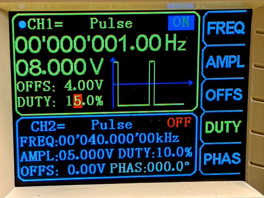
This time I used a BUZ71A MOSFET (13 A, 100 mΩ RDS) driven with a 10 V gate pulse to make sure it acted like a switch instead of a current sink.
The first attempt looked … odd:
Halogen 3V – no cap – 4ms 1A-div
The gate pulse is yellow, the drain voltage is magenta, the bulb current is cyan at 1 A/div, and the timebase ticks along at 2 ms/div.
Moving the magenta trace to the supply voltage on the other side of the bulb produces even more weirdness:
Halogen 3V – no cap – Vsupply – 4ms 1A-div
Apparently, slugging a 3 A bench supply with a 3 A pulse lasting only 4 ms causes distress of the output tract.
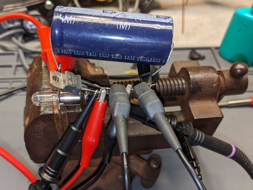
Kludging a hulking 22 mF (yes, 22000 µF) cap across the power supply provides enough local storage to make things work properly:
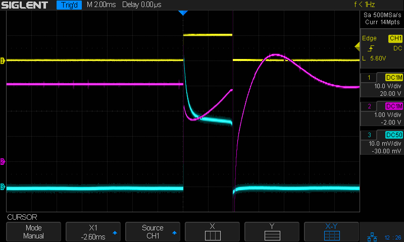
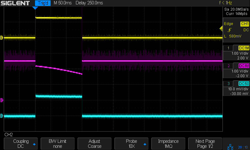
Halogen 3V – 22000µF – Vsupply – 4ms 1A-div
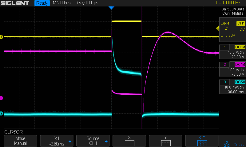
With the cap in place, the drain terminal looks less unruly:
Halogen 3V – 4ms 1A-div
The drain voltage starts at about 600 mV with the 3 A pulse, a bit more than you’d expect from the alleged 100 mΩ drain-source resistance, but those numbers are generally aspirational and the test setup leaves a lot to be desired.
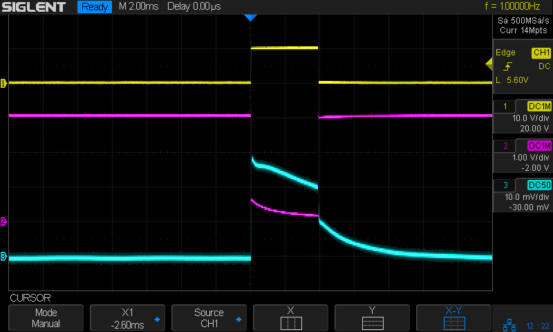
A 10 ms pulse produces a distinct flash, rather than a dull orange blip (timebase now at 10 ms/div):
Halogen 3V – 22000µF – 10ms 1A-div
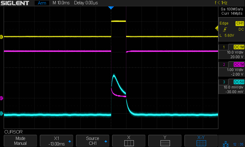
A 30 ms pulse reaches full brightness as the filament settles at normal operating temperature:
Halogen 3V – 22000µF – 30ms 1A-div
A 20 ms flash might suffice for decorative purposes, in which case each pulse requires 90 mW·s = 3 V × 1.5 A × 20 ms of energy. Running it all day requires 7.8 kW·s = 2.2 W·h, so it’s even less appealing than that old skool tungsten bulb.
Which is, of course, why LED flashlight bulbs are a thing.
A flashlight bulb emerged from the clutter, which prompted me to ask if it might make an interesting blinky. Spoiler: probably not.
The bulb had “2.4 V 0.7 A” stamped on its shell, so the test setup looked like this:
Flashlight bulb test setup
A list seems helpful:
Solder wires to bulb in lieu of a socket
Bench supply at 2.4 V
Grossly abused 2N3904 NPN transistor as a switch
Function generator pulsing the base
Scope voltage probes on base (yellow) and collector (magenta)
Tek current probe on bench supply lead (cyan, 500 mA/div)
The function generator has a 50 Ω output, so depend on it to limit the base current just like it was a resistor. The output voltage is symmetric around 0 V, so apply an offset of half the peak-to-peak signal to get a positive-going pulse:
Flashlight bulb test – function gen setup
A 150 ms pulse gives the bulb just barely enough energy to light as a little orange blip, with the collector voltage dropping as the filament heats up and its resistance increases:
Tungsten 2.4V 700mA – 150ms
Given 350 ms to heat up, the bulb produces a nice white-hot flash:
Tungsten 2.4V 700mA – 350ms
The poor transistor acts as a 600 mA constant current sink, which isn’t surprising given its 300 mA absolute maximum current rating.
Homework: figure the base drive and current gain
Protip: don’t do that to a cherished transistor
The bulb resistance starts out at 0.5 Ω and rises to 2.5 Ω when the filament glows white-hot at the end of the pulse.
Something like 250 ms produces a noticeable blink, requiring 360 mW·s = 2.4 V × 600 mA × 250 ms from the power supply. Blinking once every ten seconds all day means 8640 pulses for a total energy of 864 mW·hr; call it 1 W·hr.
A pair of (fresh) AA alkaline cells provide 7.5 W·hr for maybe a week of blinkiness.
A not-dead-yet 18650 lithium cell might offer 15 W·hr, but running the bulb from 3.7-ish V, rather than 3-ish V, increases the energy per pulse by 20% and decreases the run time correspondingly.
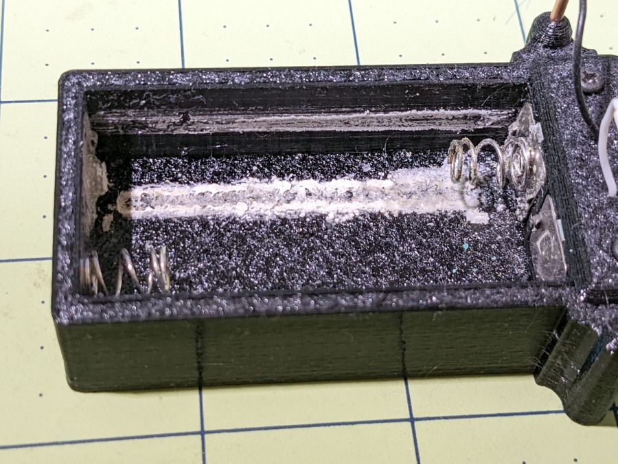
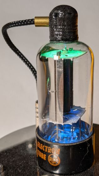
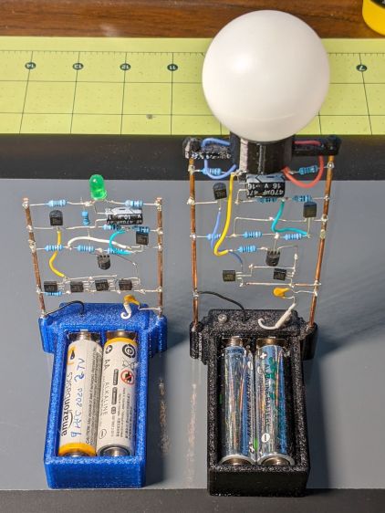
These two discrete LM3909 circuits recently stopped blinking:
LM3909 AA alkaline – Green and Blue
The green LED (on the left) took six months to wear its pair of not-dead-yet AA alkalines from 2.7 V down to nearly zero.
The blue LED in the radome took two months to go from 1.0 V (!) to nearly zero. It didn’t start very bright and went decidedly dim along the way, but the LM3909 circuitry still managed to jam a few microamps through the LED.
In both cases, one of the cells was reverse-charged by a few hundred millivolts, although neither leaked.
Both got another set of not-quite-dead AA cells and they’re back in action.