Ed Nisley's Blog: Shop notes, electronics, firmware, machinery, 3D printing, laser cuttery, and curiosities. Contents: 100% human thinking, 0% AI slop.
This metric micrometer has resided in my tool chest just short of forever:
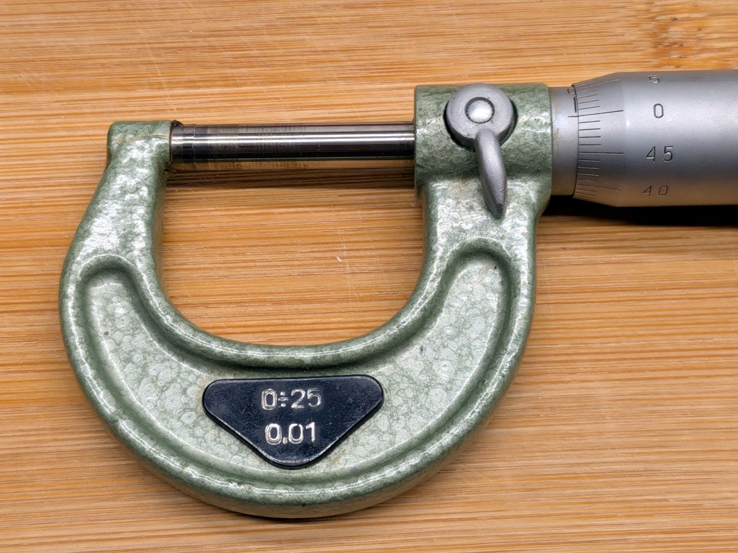
Metric micrometer – detail
During that entire time, it read 0.025 mm too high: when the spindle was on the anvil, as shown, the thimble sat 2-½ divisions above the index line. Not off by much, but an annoying bit of mental arithmetic every time.
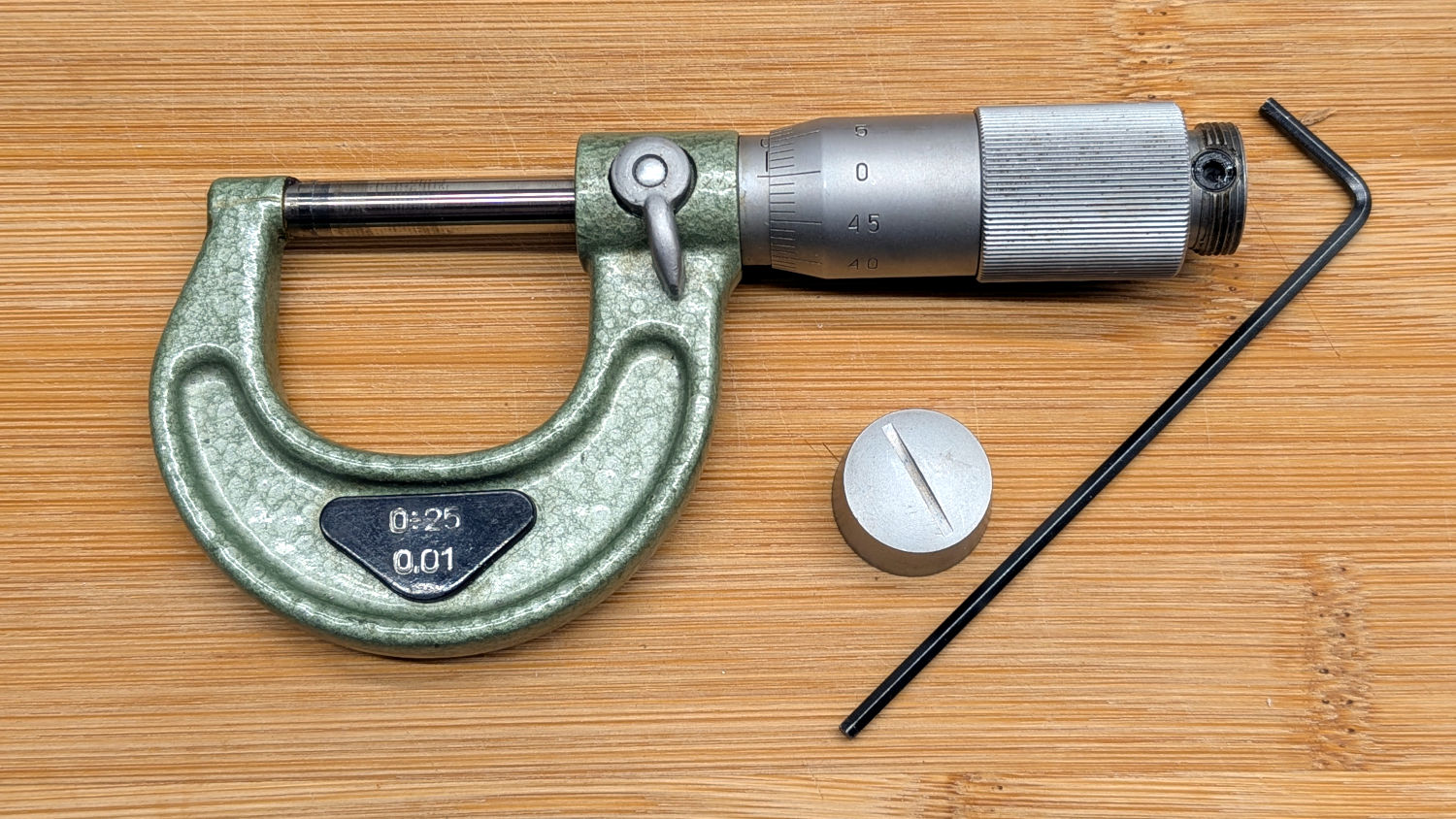
A cap unscrews from the end of the thimble, revealing the setscrew locking the thimble to the spindle:
Metric micrometer – overview
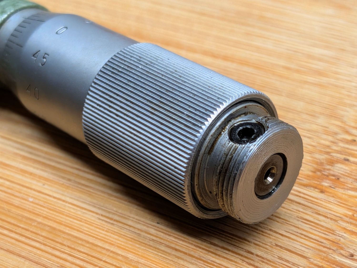
Unfortunately, loosening the setscrew (with a 2 mm hex wrench) didn’t release the thimble:
Metric micrometer – thimble setscrew
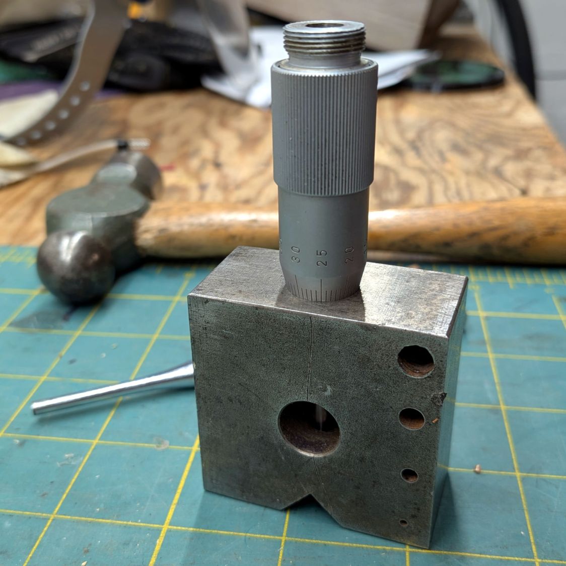
After steeping the joint in Kroil penetrating oil for while, I stood the thimble on the bench block and gently tapped the spindle with a punch, just enough to break it free:
Metric micrometer – spindle adjustment
Then it was a matter of screwing the thimble back onto the frame until the spindle contacted the anvil, continuing to screw the thimble until the 0 line matched the index line, and tightening the setscrew. There was some slippage as the Kroil worked its way further into the joint, but a firm grip on both got the job done.
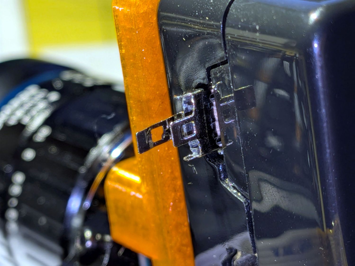
While setting up a Raspberry Pi camera, I had occasion to pull out its USB power cable, whereupon grabbing the camera while unscrewing it from the tripod felt unusually sharp:
Micro-B USB – RPi jack
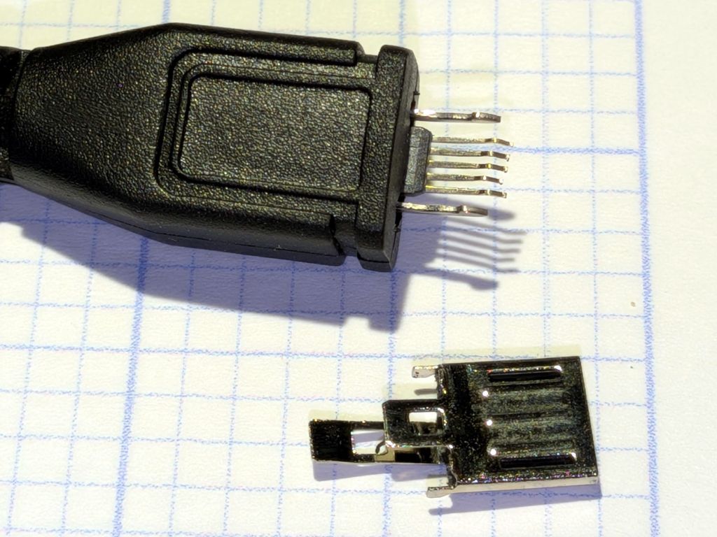
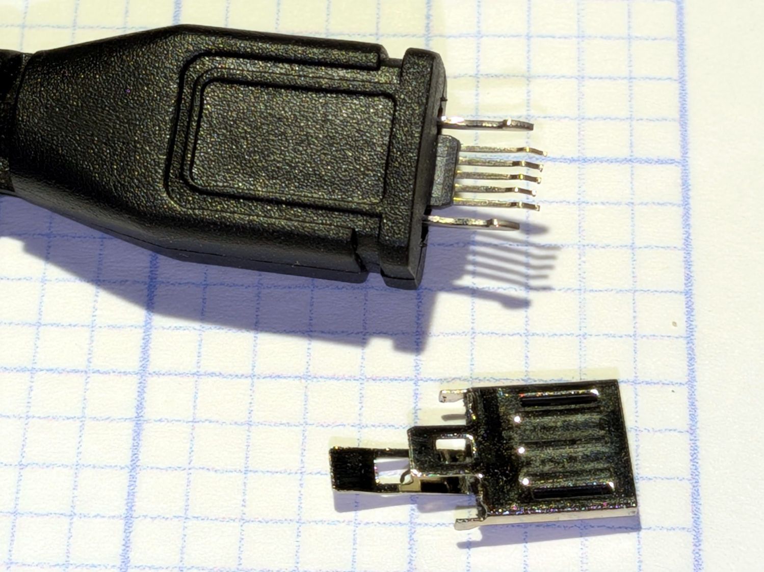
It seems the wall wart’s USB Micro-B connector pulled apart:
Micro-B USB connector – disembowled
Somewhat to my surprise, it was a CanaKit 5 V 2.5 A wall wart, definitely not the cheapest piece of junk ever made by the hand of man. On the other paw, it’s been around for quite a while, so …
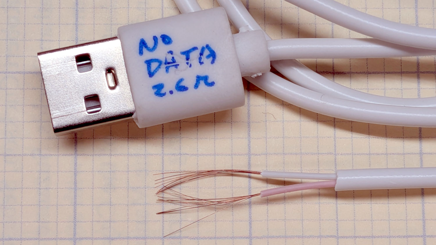
Even I will agree that’s not a repairable failure, so I planned to splice in a Micro-B connector from a volunteer chosen from the Box o’ USB Micro-B Cables:
Each of those conductors appears to be made up of nine springy copper-colored 0.06 mm strands, somewhat smaller than 40 AWG: not what you want on the business end of a 2.5 A wall wart. I had previously measured the cable’s overall resistance with a surprisingly useful Treedix USB Cable Tester and it was on the very high end of the charge-only cable collection.
So I soldered a female USB-A breakout from the Drawer o’ USB Breakouts to the wall wart’s wires, snapped a 3D printed case around it, got a good (0.26 Ω) A-to-Micro-B cable from the Box o’ USB Adapters, and moved on.
Our ancient Branson 200 Ultrasonic Cleaner began behaving erratically due to water seeping under the rather casual seal from last year’s fix. Although drying the switches let it start up again, it would run for only a few seconds before shutting down again, which suggested a deeper problem than just the switches.
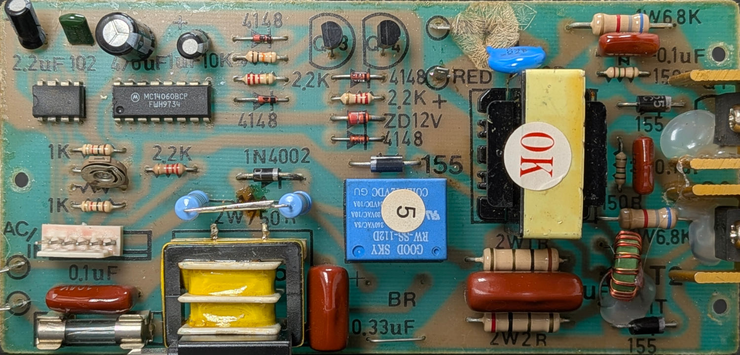
Take a picture of the PCB’s component side:
Branson 200 Ultrasonic Cleaner – PCB component side
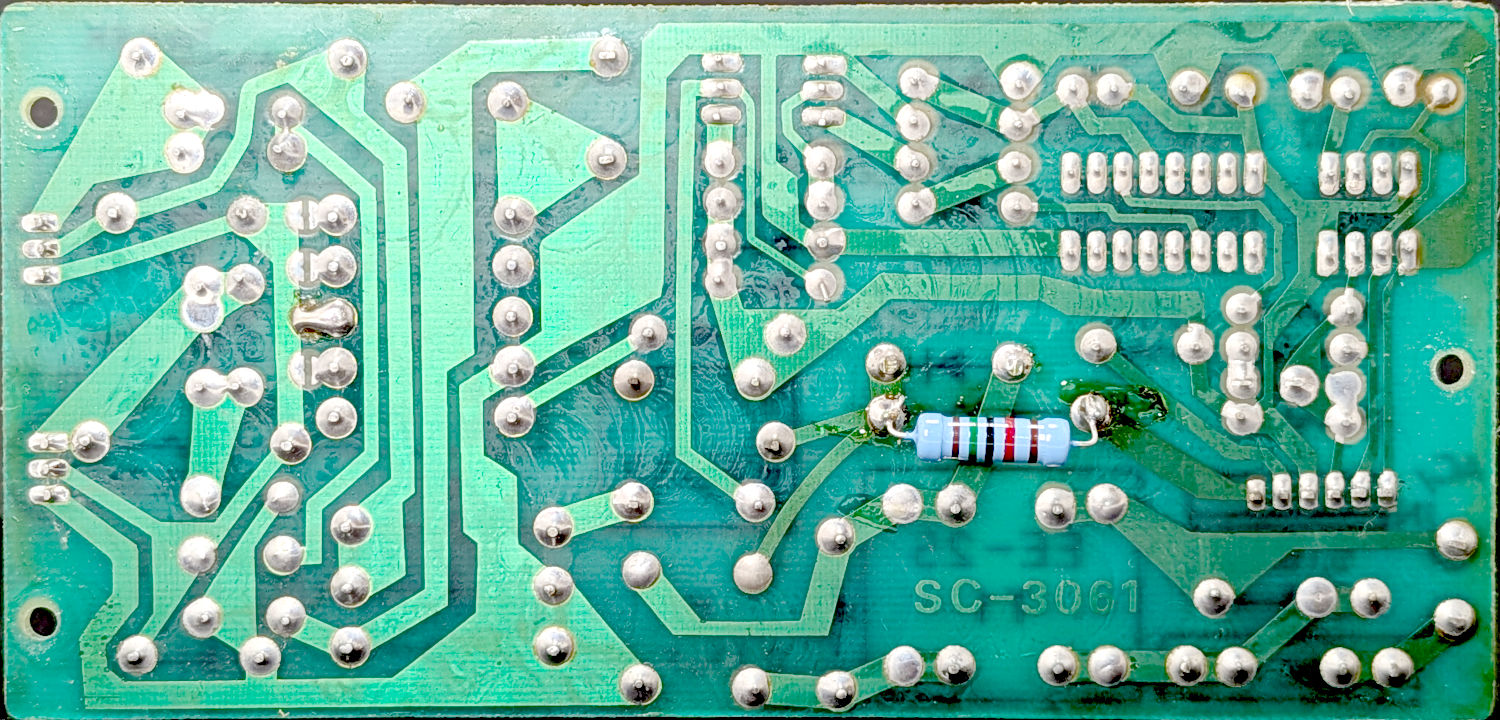
And of the solder side:
Branson 200 Ultrasonic Cleaner – PCB solder side
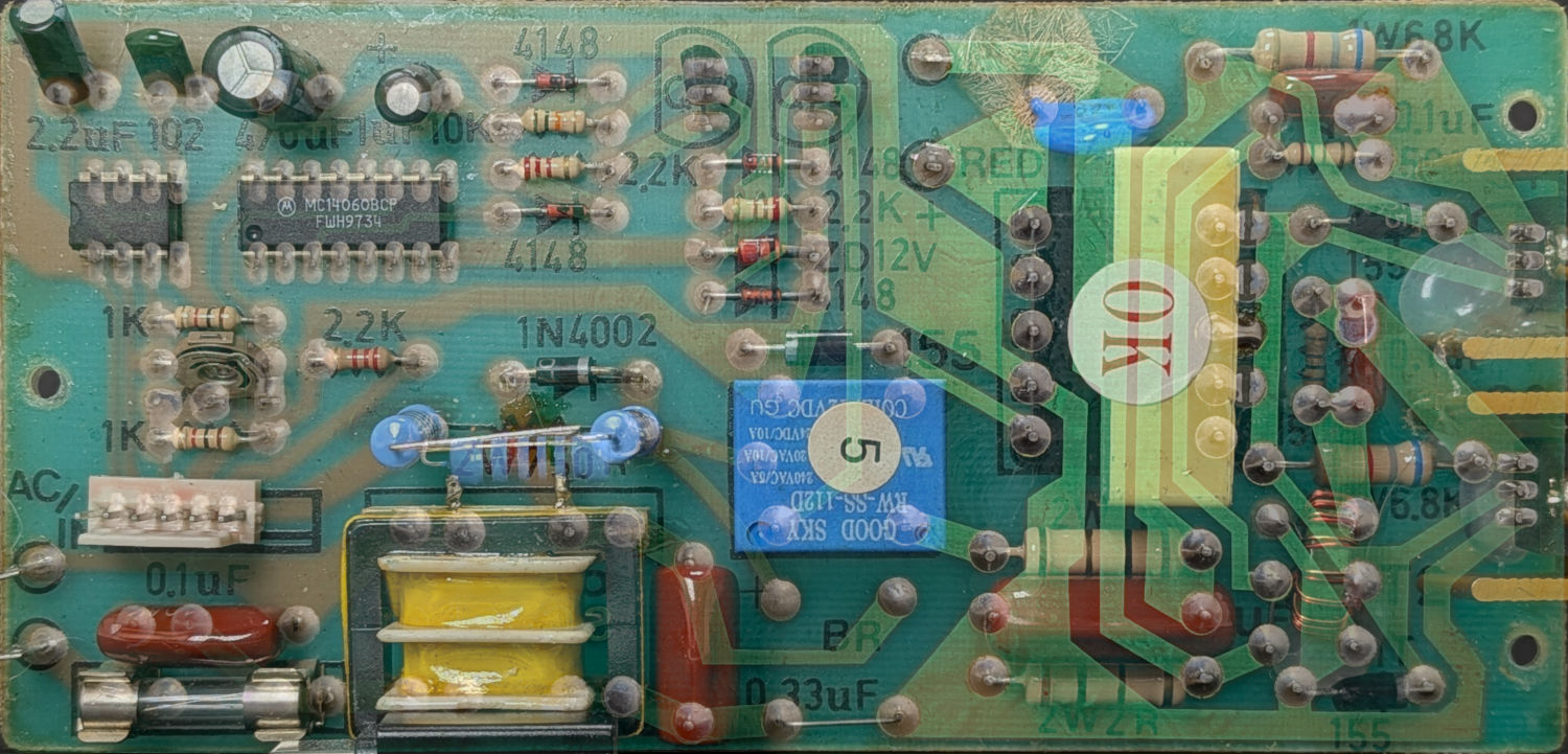
Transform those pictures to be the nice real rectangles shown above, resize to a common pixel format, mirror the solder side, turn it into a layer atop the component side, then tweak its opacity to make both sides visible at once:
Branson 200 Ultrasonic Cleaner – PCB overlay
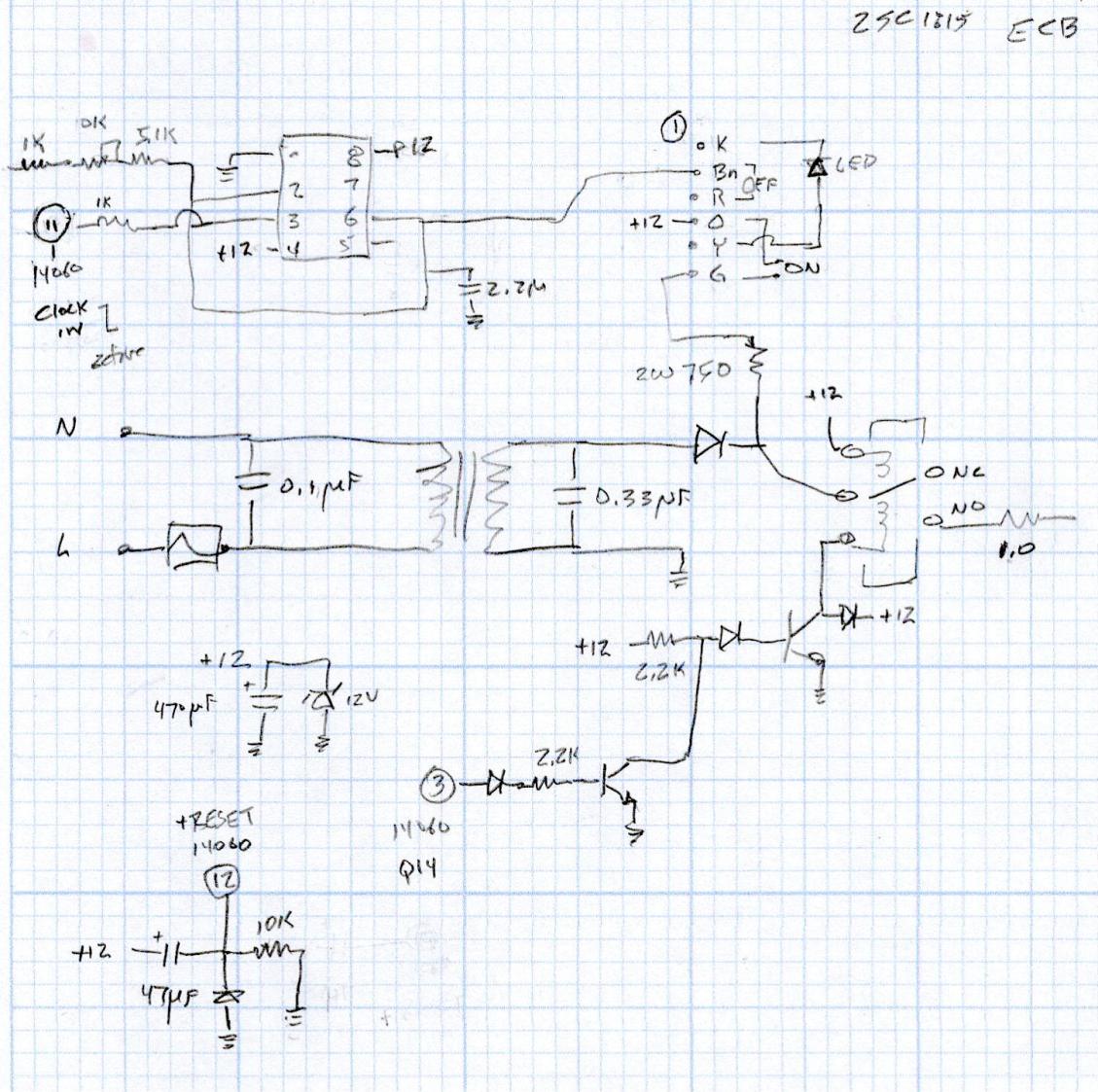
Some pondering produces a partial schematic of the left half of the board:
The 1:1 transformer is constantly powered, so the ON button connects the 120 V (!) half-wave rectified output to the +12V supply bus, with the 750 Ω resistor dropping most of the voltage while the switch is pressed.
The hotwired +12V supply forces the relay closed, which (in some as-yet unidentified way) fires up a +12V power source to hold the relay closed, with the 555 timer driving an MC14060 14-bit divider to count down the time until it turns itself off.
Reminder: this design dates back to the days when a pair of chips and a handful of through-hole components cost less than one of those fancy microcontroller thingies.
Plug the cleaner into an isolation transformer and trace the half-wave rectified signal through ON button to find it got all the way to the contact on the end of the orange wire in the connector, but did not reach the pin header on the PCB.
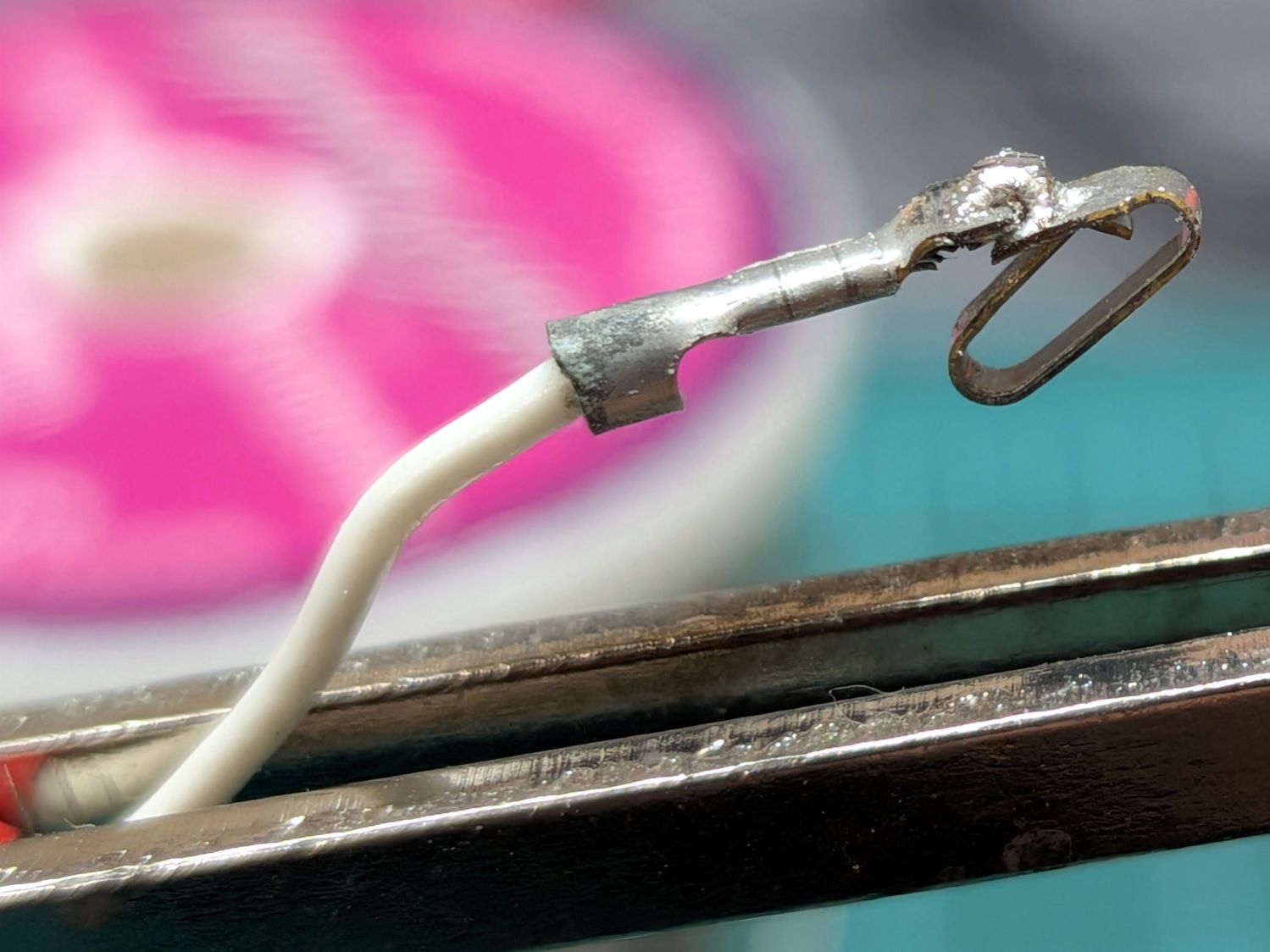
A closer look at the connector revealed a broken contact on the white wire, which I (rather crudely) soldered together while considering my choices:
Branson 200 Ultrasonic Cleaner – soldered contact
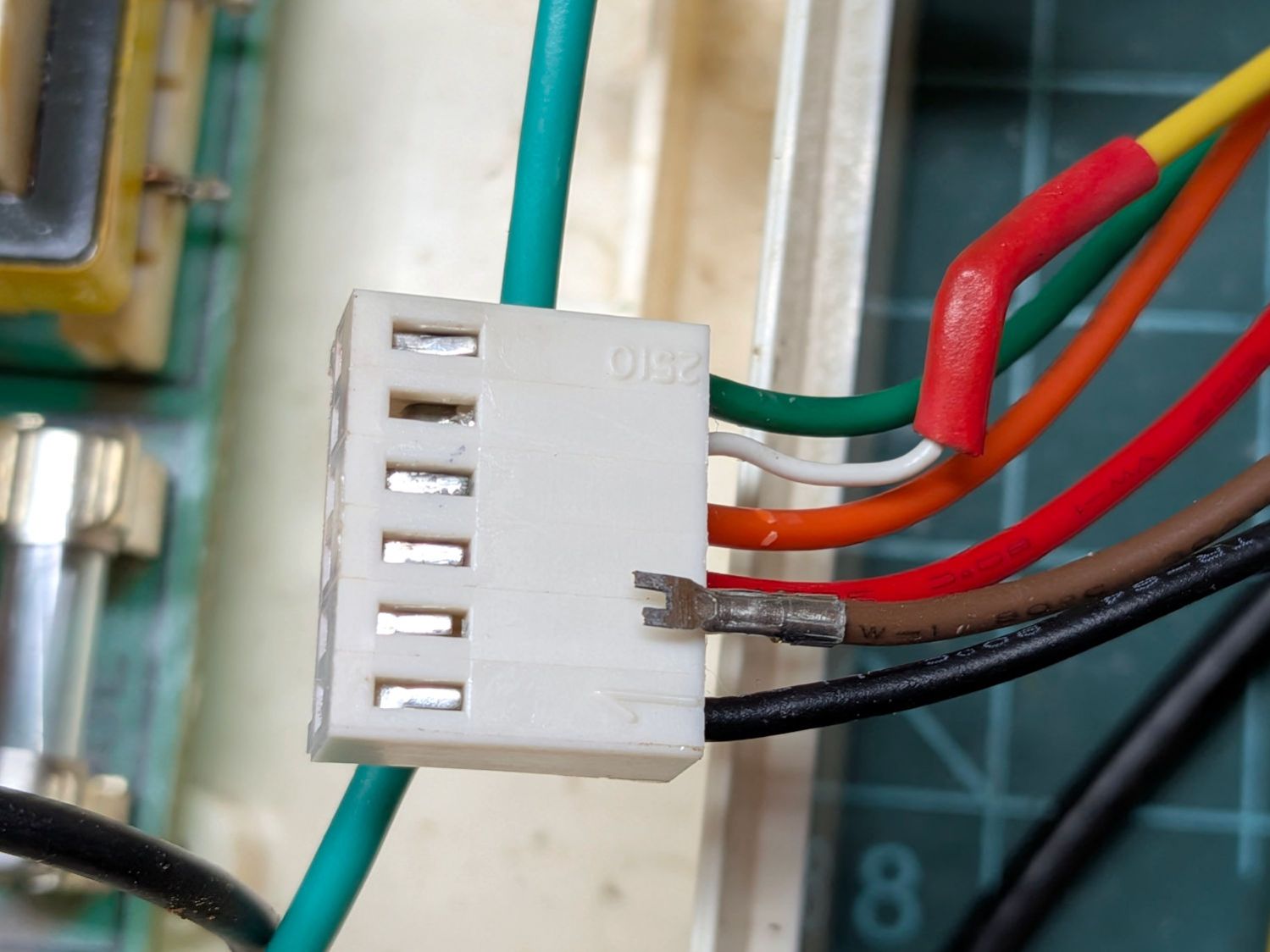
While plugging that wire back in place, this happened:
Branson 200 Ultrasonic Cleaner – another broken contact
Neither of those are the (presumably) similarly failed orange wire, but even I can get a clue from three similar failures.
So I replaced the OEM connector with a JST-XHP 2.54 mm connector from an assortment I got for another project, replaced the chunky 22 AWG wires with flexy 26 AWG silicone wires in the same cheerful rainbow colors, and it began working perfectly again.
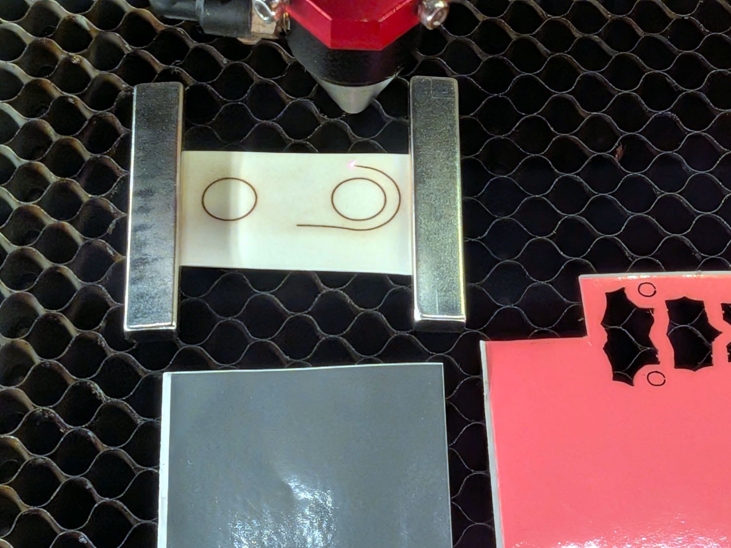
The buttons needed another water seal, so I tweaked the previous layout to kiss-cut GITD tape and through-cut colorful vinyl sheets:
Branson 200 Ultrasonic Cleaner – power button cutting
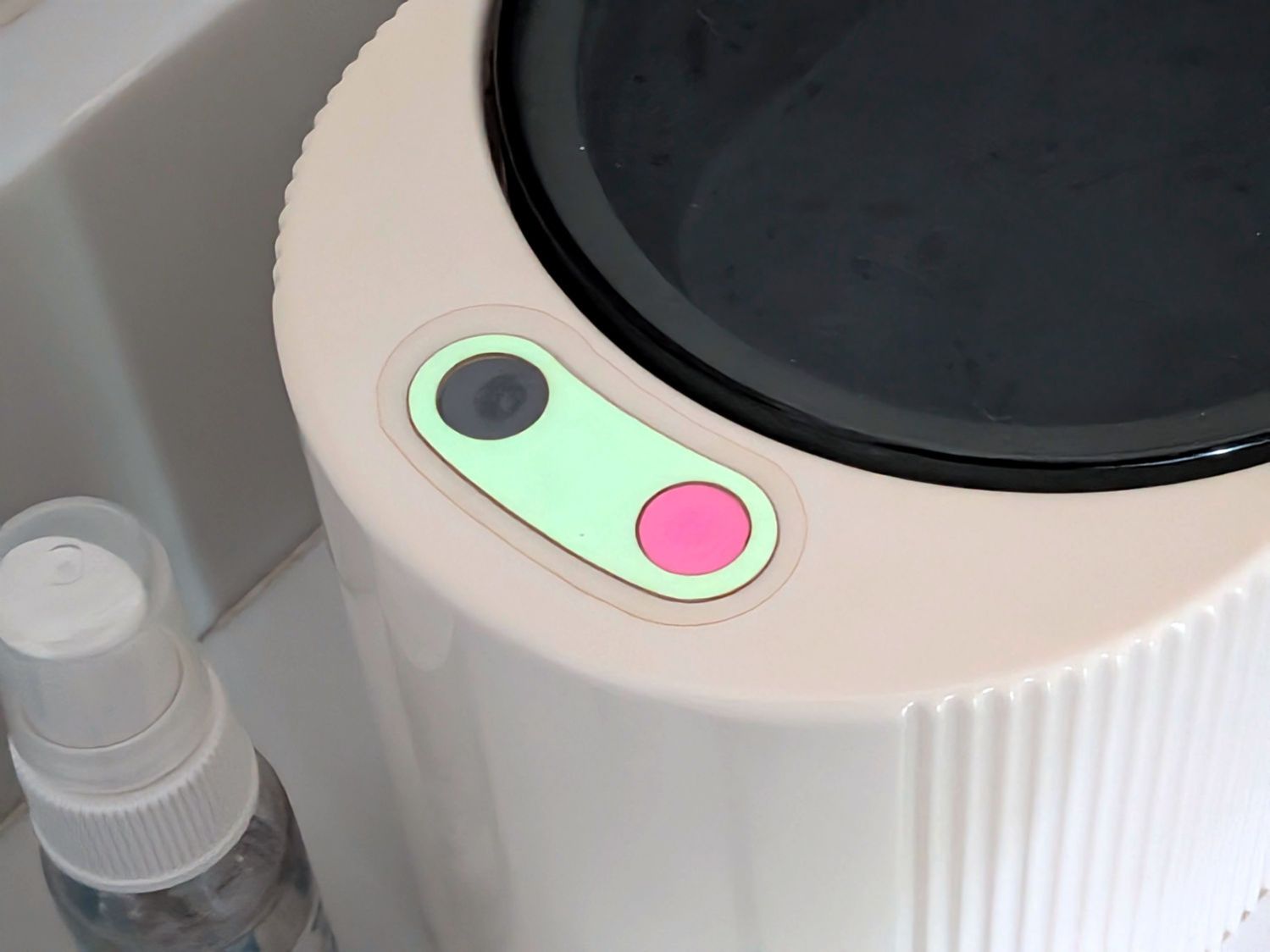
Capped with a transparent cover sheet cut from a pack of PDA screen protectors (remember PDAs?):
Branson 200 Ultrasonic Cleaner – power button cover
In truth, the GITD tape is too thick, so I’ll probably repeat this dance later this year.
FWIW, I was totally ready to buy a new ultrasonic cleaner, but all of them have scathing one-star Amazon reviews, to the extent I decided fixing this cleaner would be much easier than fixing a new one that’s been cheapnified to the point of no return. A common complaint seems to be water leaking into their capacitive switches and killing the circuitry stone cold dead: not an improvement over this one.
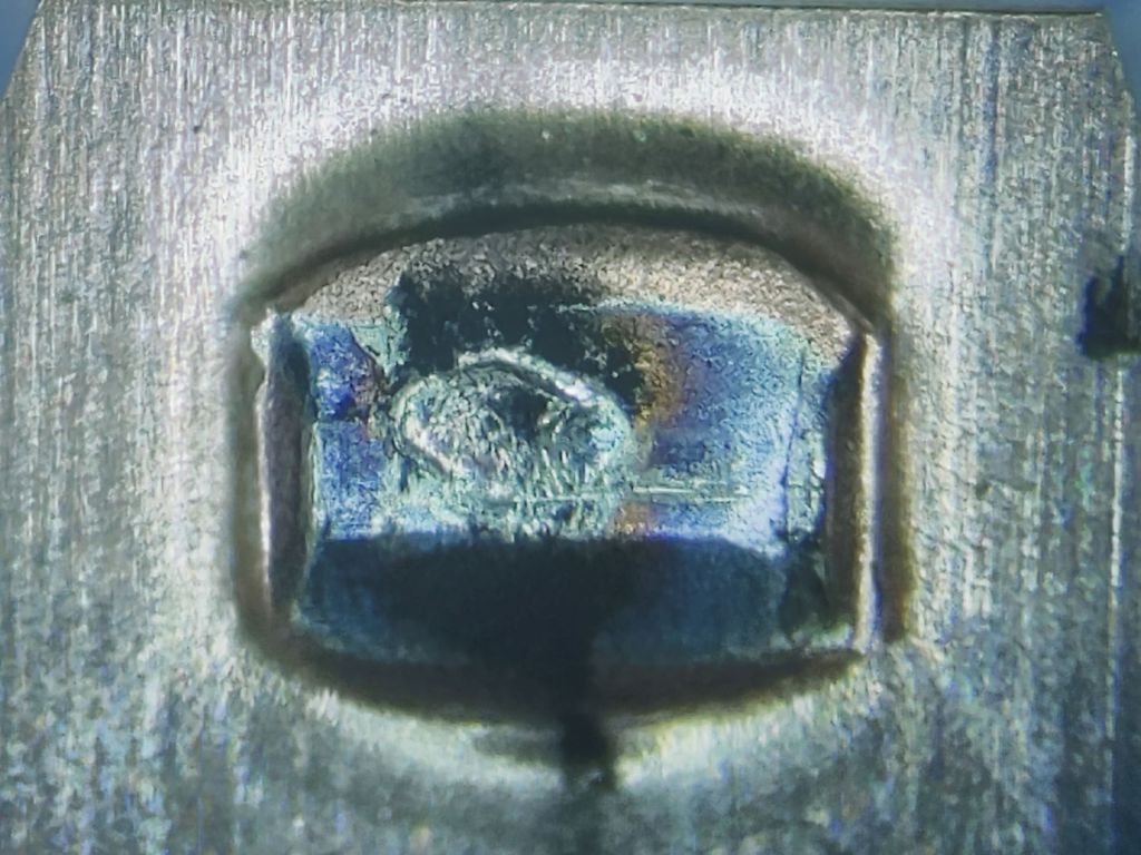
I don’t know what permanently opens the circuit in there, but it definitely happened. The contacts remain unblemished, so they were pressed firmly together until the end.
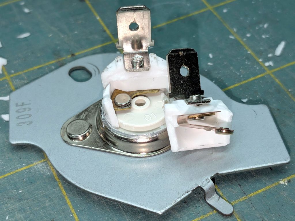
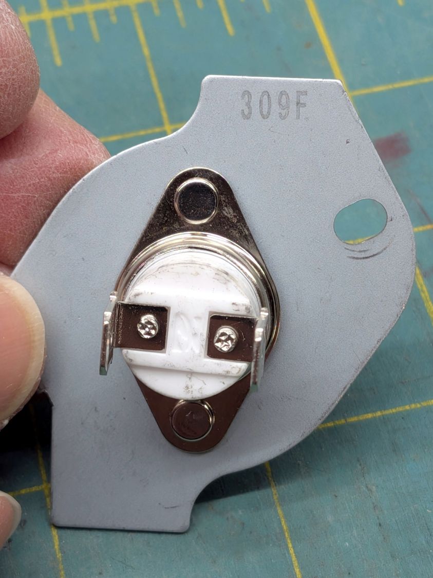
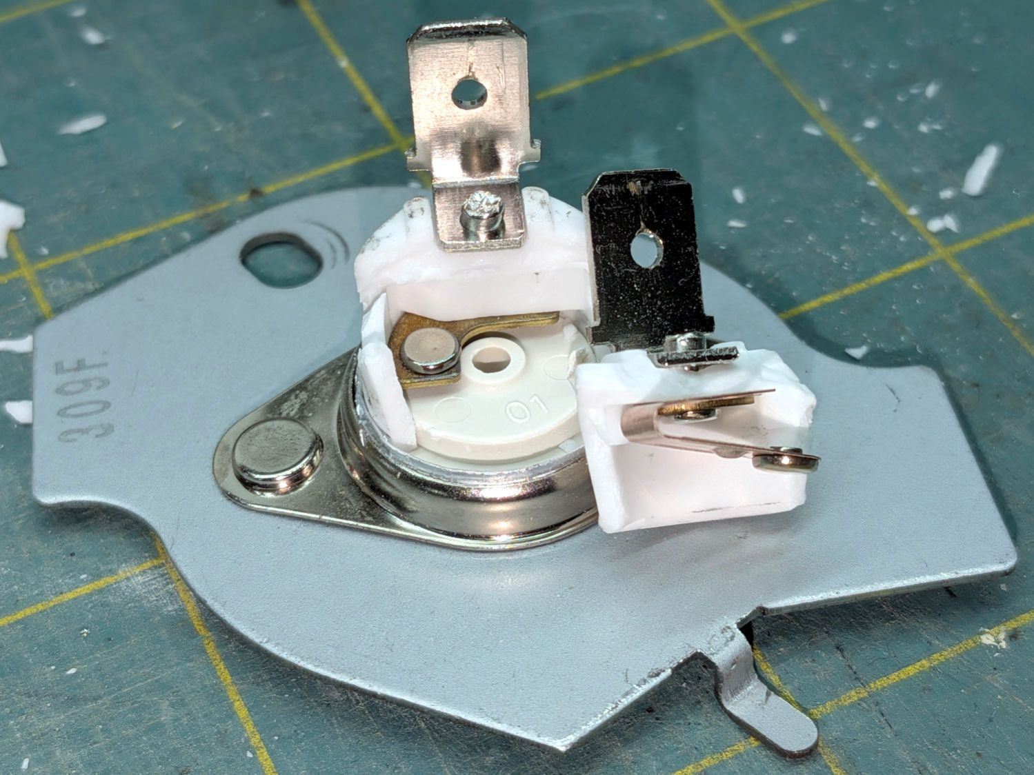
With nothing to lose, I reinstalled the Thermal Cutoff I removed last year (*) and the dryer works fine again.
It is possible lint accumulating in the filter bag I added to the exhaust vent restricted the airflow enough to overheat the cutoff, but the Operating Thermostat should keep the air around 155 °F and the Hi Limit thermostat should have tripped at 250 °F, long before the temperature reached 350°F.
Another cutoff will arrive shortly and will remain in the Box o’ Dryer Parts against future need.
(*) Which is why I keep the old parts around, because a dubious part on hand is much better than the new part I might not be able to get due to, oh, “supply chain issues”.
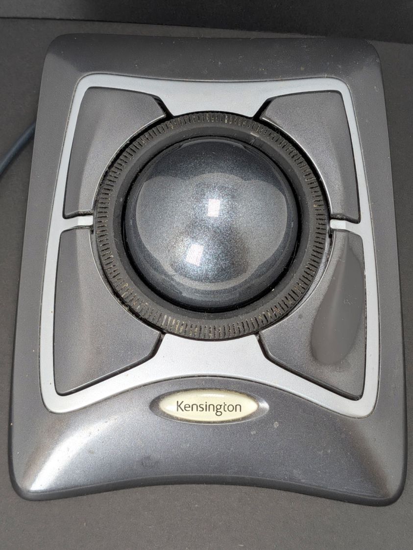
You can tell that button has done a lot of clicking:
Kensington Expert Mouse Trackball – worn button
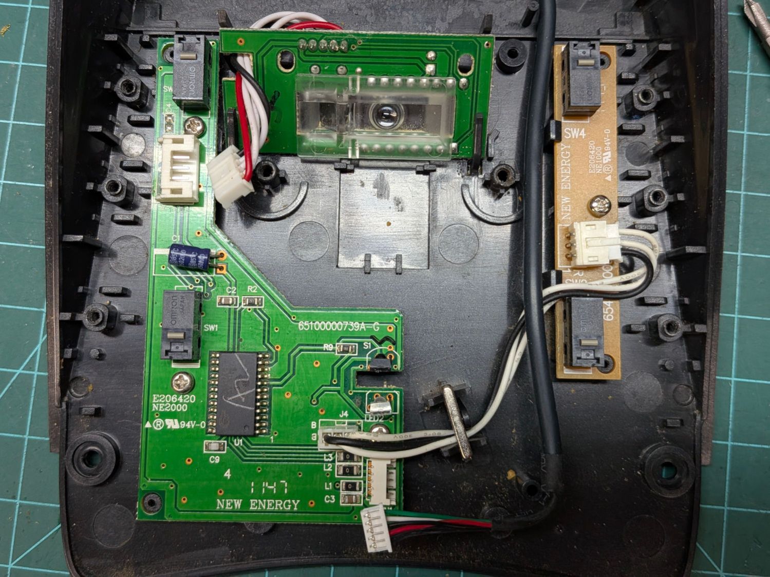
The switch layout comes as no surprise:
Kensington Expert Mouse Trackball – switch layout
Those are Genuine Omron D2F-01 SPDT switches and the replacements are Genuine Anonymous D2F-01F. While I had the cover off, I replaced all four switches.
Protip: The black cable on the right must go under the three wires between the PCBs. Arranged as shown, the scroll ring will drag on the cable.
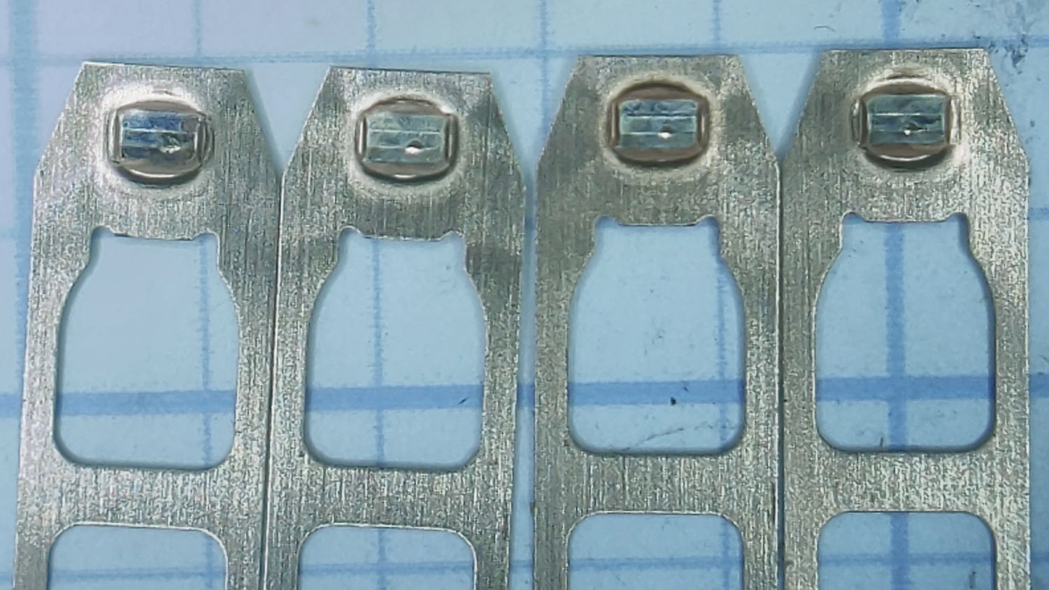
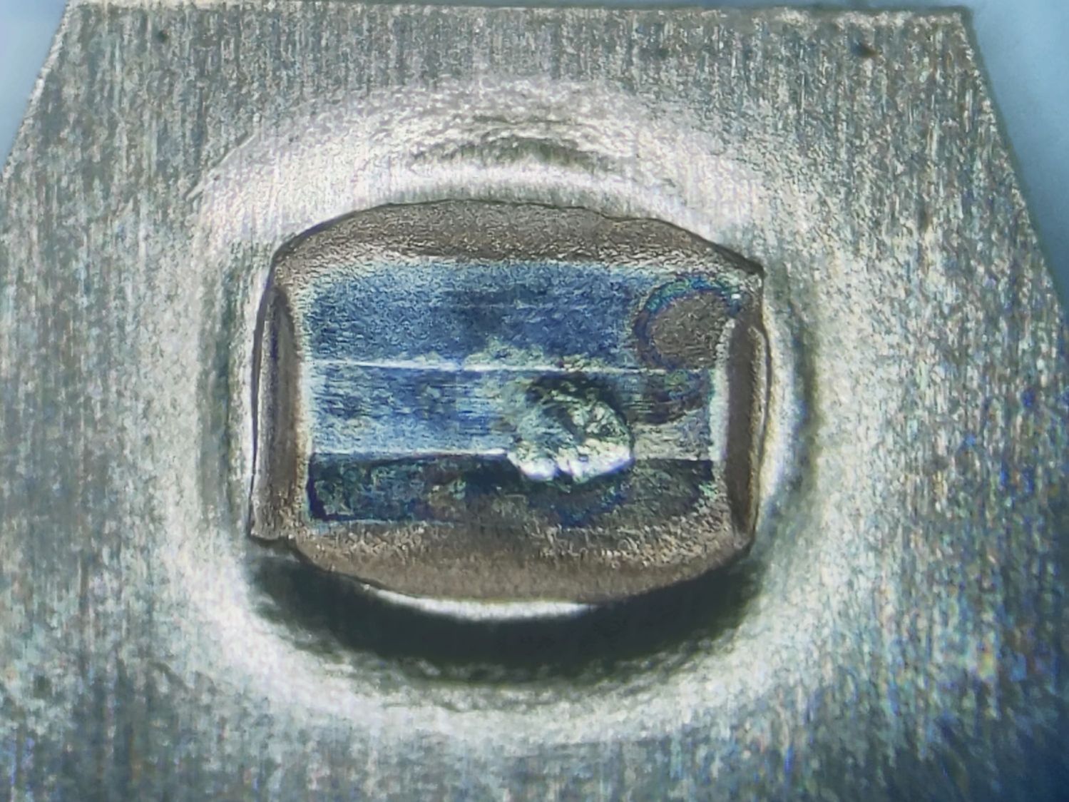
I dismantled the switches and put their Common bar under the microscope. I believe these contacts rest on the Normally Closed switch terminal, which is electrically inert:
Kensington Expert Mouse Trackball – NC contacts
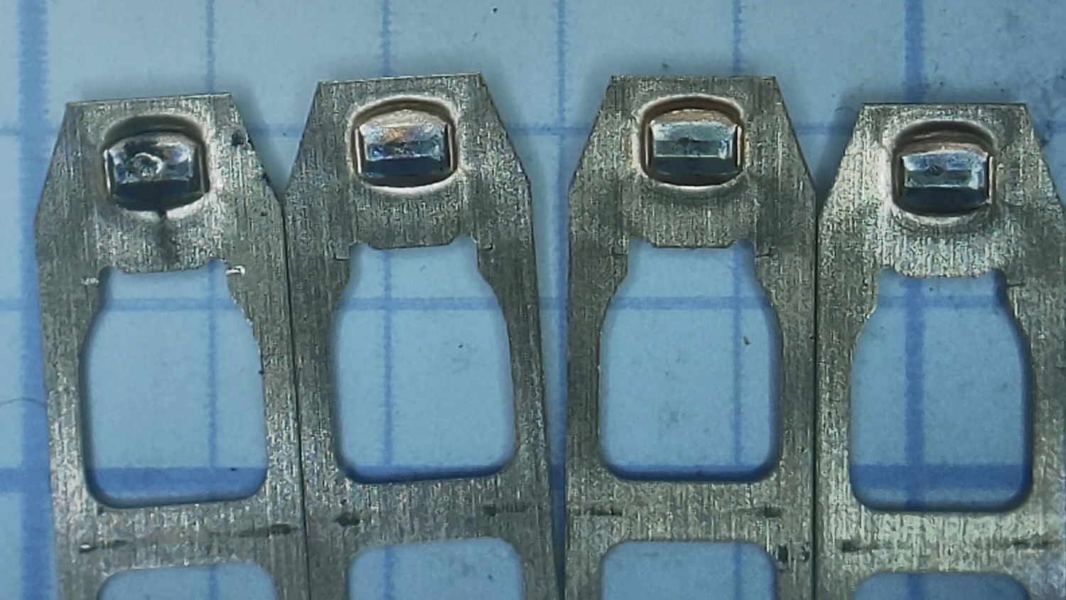
Three of them have about the same amount of wear:
Kensington Expert Mouse Trackball – NC contact 2
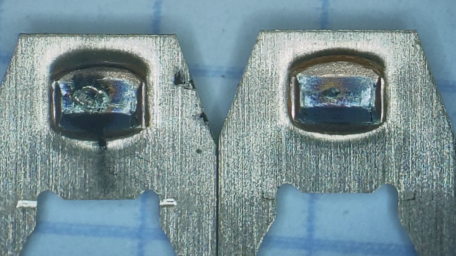
The leftmost one looks worse:
Kensington Expert Mouse Trackball – NC contact 1
Flipping them over (in the same order) exposes what I think are their Normally Open contacts responsible for all the button action:
Kensington Expert Mouse Trackball – NO contacts
Again, the rightmost three look about the same and the contact on the left shows more wear, plus what looks like a soot streak:
Kensington Expert Mouse Trackball – NO Contacts 1 2
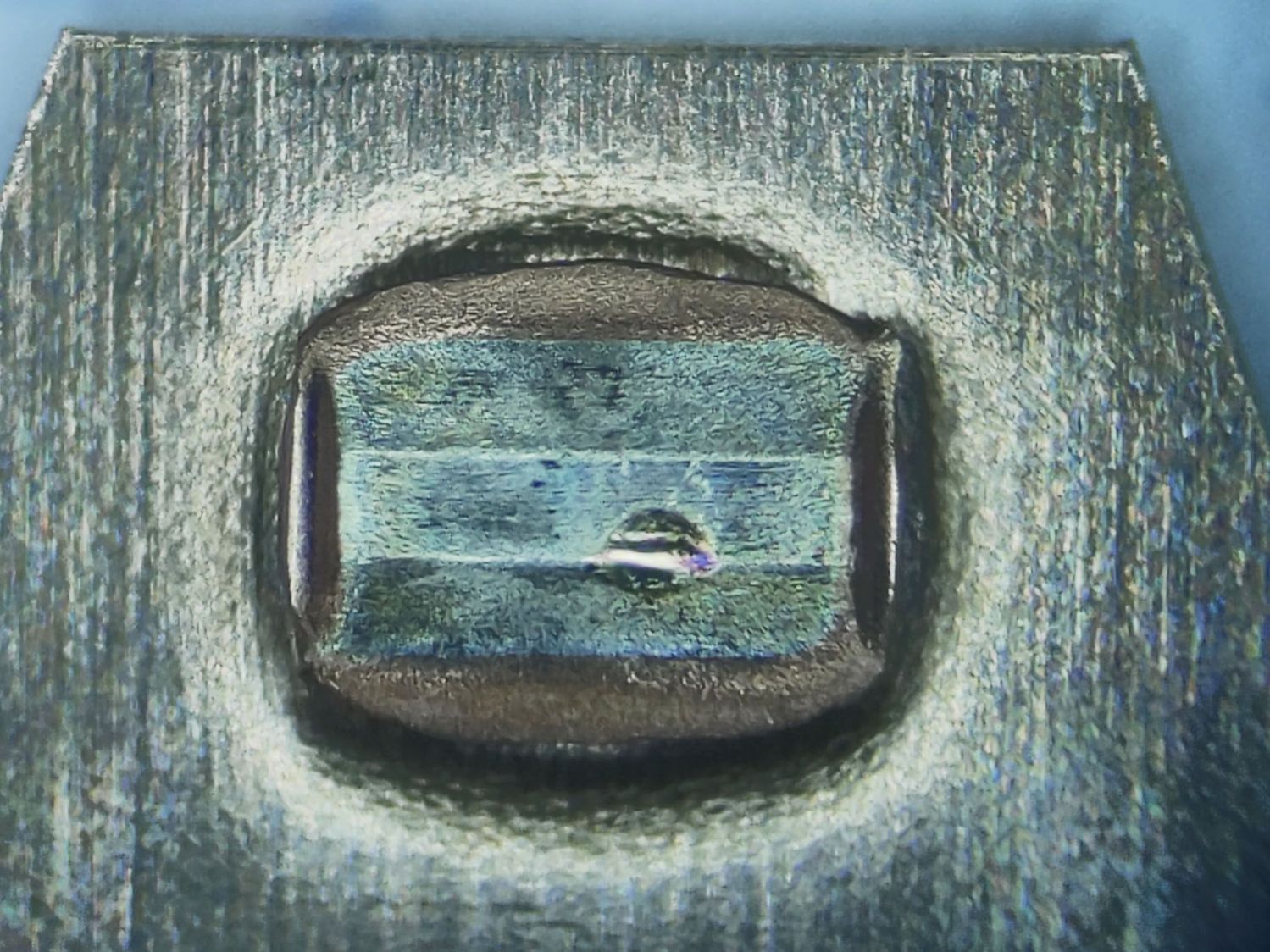
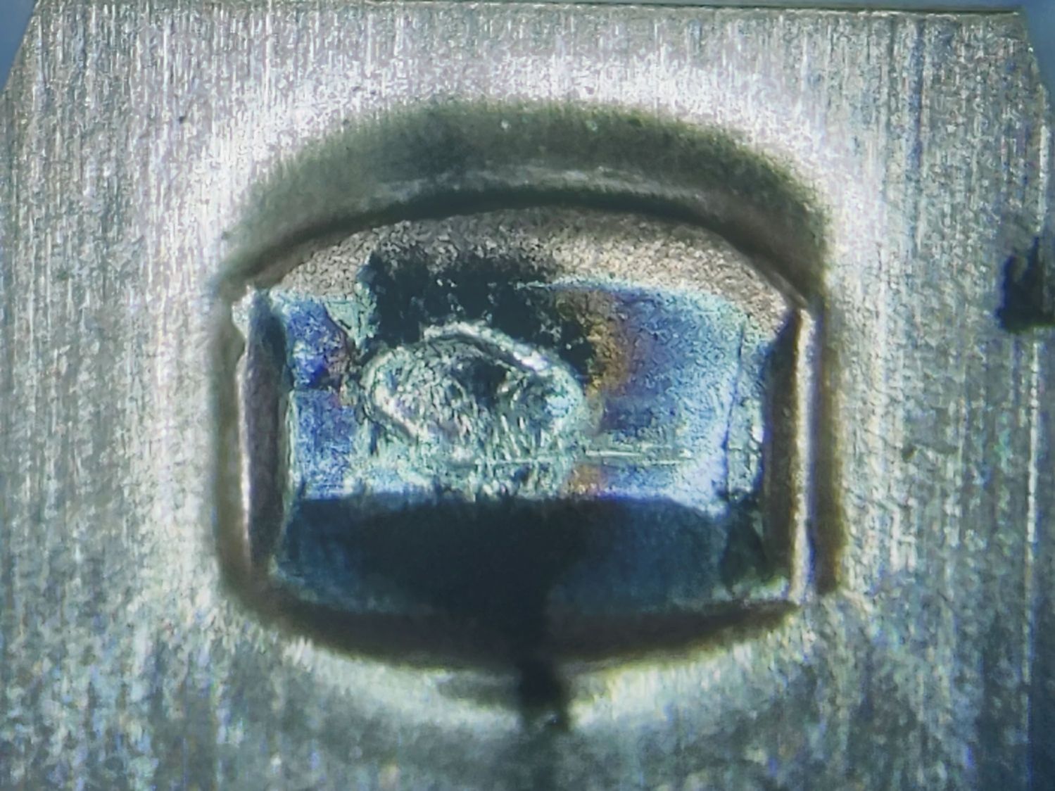
A closer look:
Kensington Expert Mouse Trackball – NO Contact 1
These things operate at logic levels, so most of the damage surely comes from mechanical erosion and the soot is pulverized metal.
While waiting for the switches to arrive, I deployed an Expert Mouse Trackball from a PC in the Basement Shop. The repaired unit went down there, so its new switches should survive longer even if they’re of mediocre quality.
Our square oak stool developed an annoying creak in two of its legs, resulting in a teardown & glue-up.
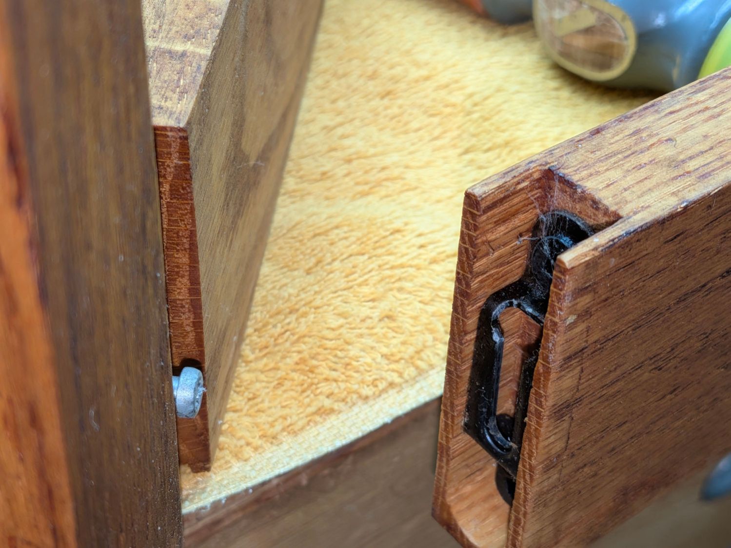
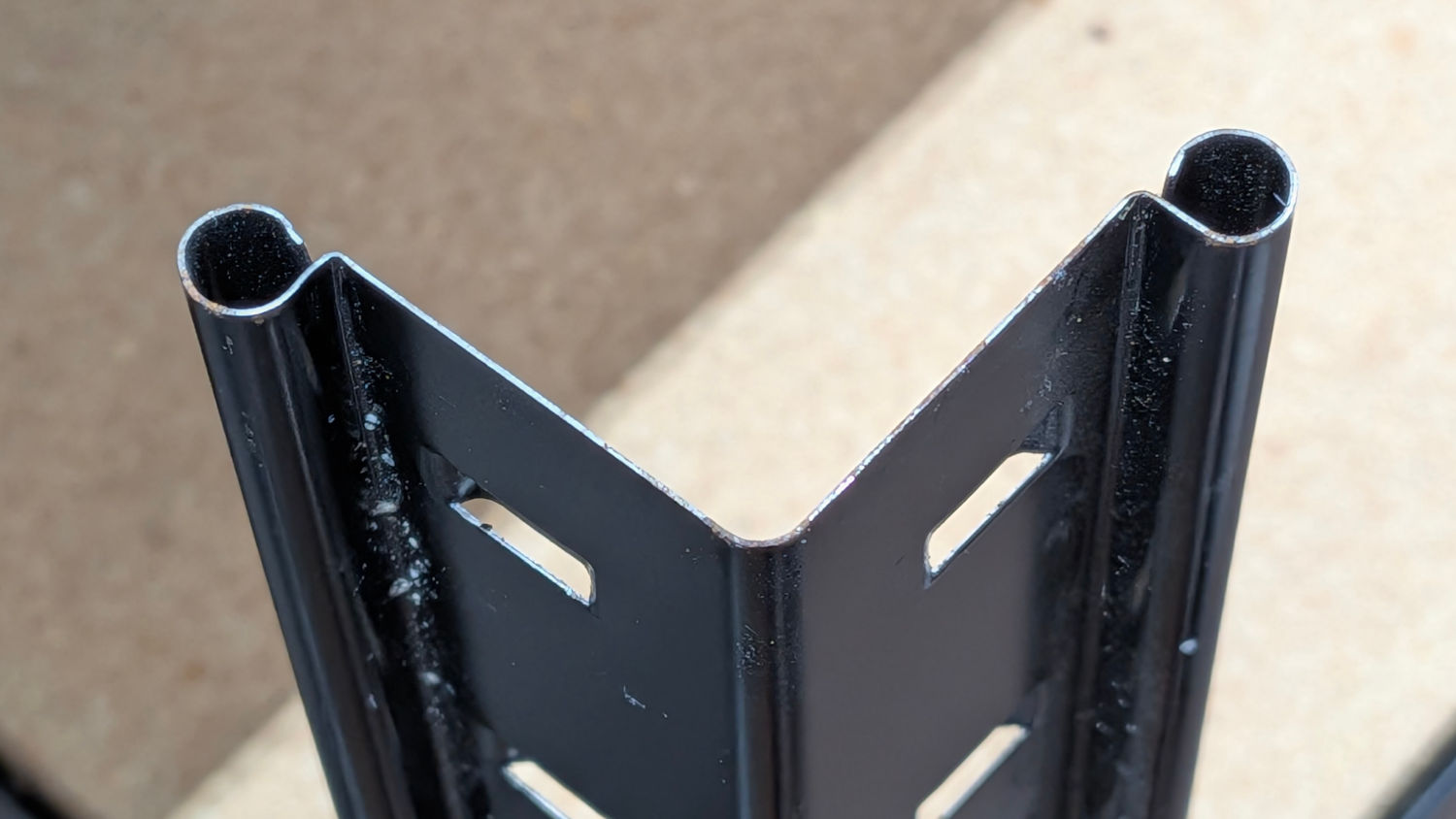
The legs come in pairs held in place by snug screw fittings:
Oak Stool Legs – mechanical joint
The screw on the left slides into the tapered fitting on the right and latches firmly in place: no creaks in there! I have no idea what that fitting is called; my search-fu is unavailing.
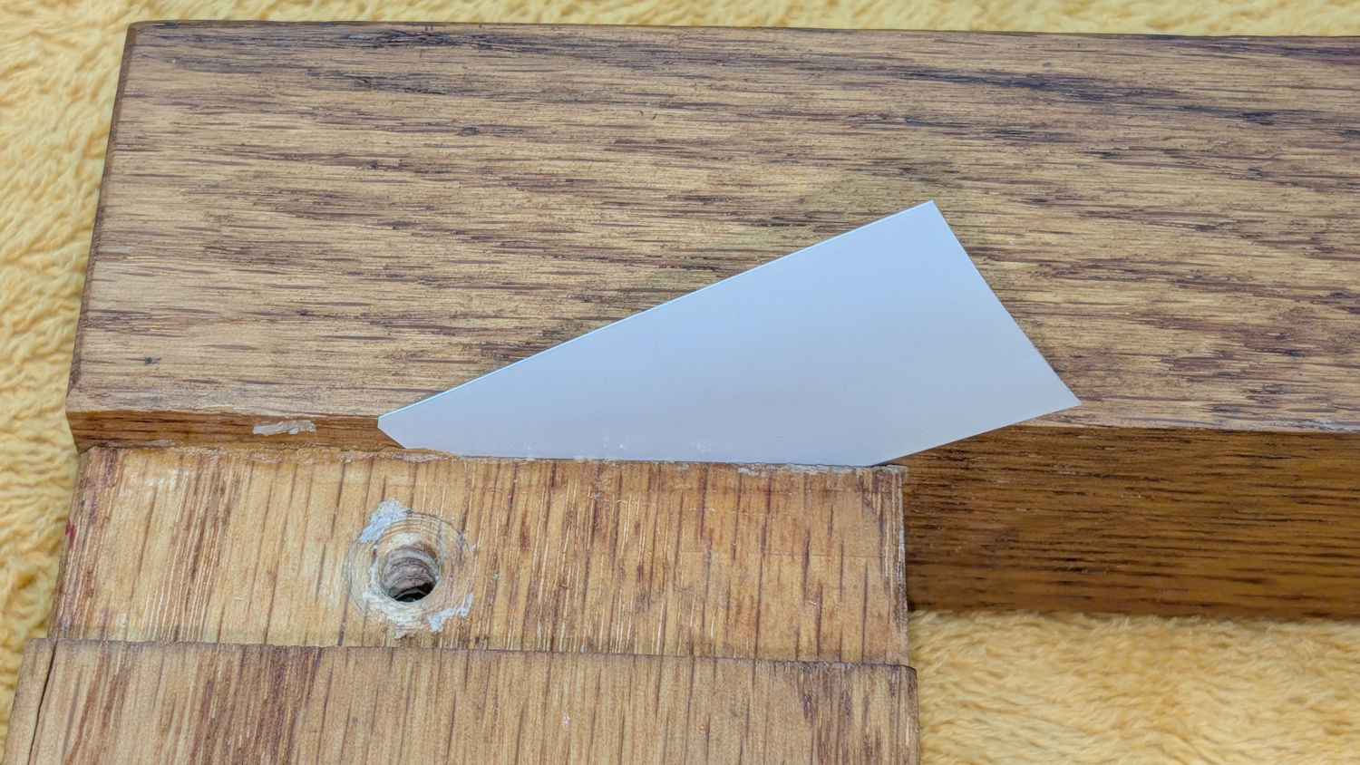
In any event, the offending legs were loose enough to admit a 6 mil = 0.16 mm miniblind snippet shim:
Oak Stool Legs – loose joint
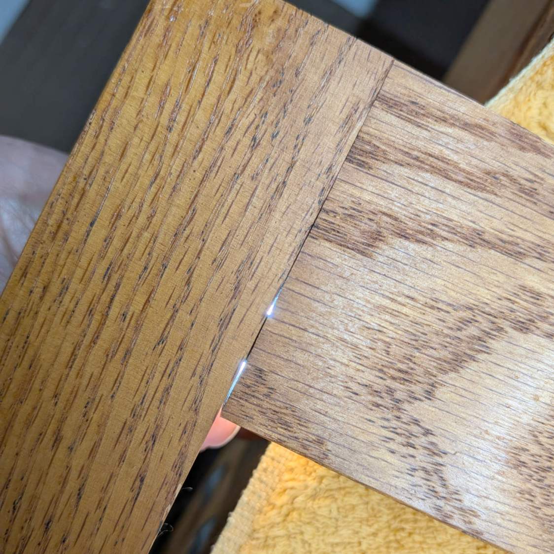
Our Young Engineer, having taken up woodworking as a serious hobby, suggested the joint might have a loose dowel, which will be difficult to fix. Peering into the gap with a flashlight below showed that was the case:
Oak Stool Legs – dowel revealed
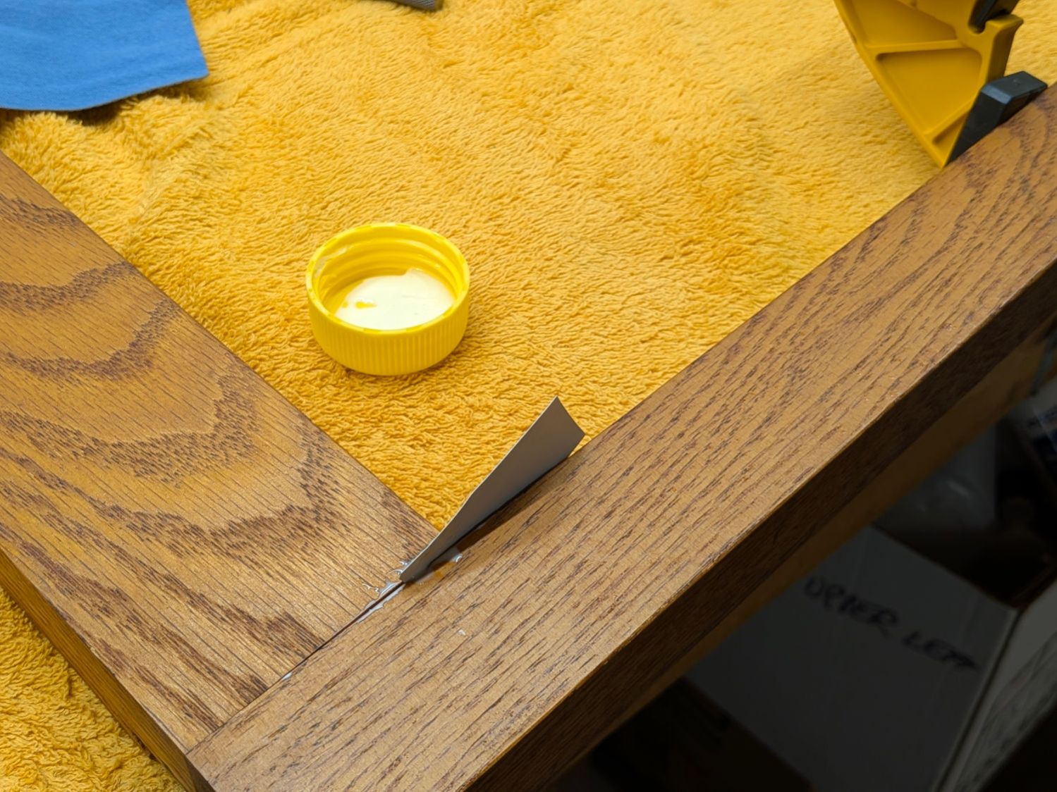
While it might be possible to force the joint apart enough to properly re-glue the dowels, I opted for a half measure by applying a spreader and easing wood glue into the gaps using the shim:
Oak Stool Legs – gluing
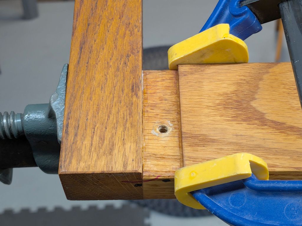
An overnight session with the pipe clamp eliminated the creak, at least for now:
Oak Stool Legs – clamping
The blue-and-yellow clamp fixed the loose splinter you didn’t notice in the second picture.
Traces of glue along inside the joints suggest I’d done something like in the deep past. Ideally, I’ve learned enough to get it right this time.
This file contains hidden or bidirectional Unicode text that may be interpreted or compiled differently than what appears below. To review, open the file in an editor that reveals hidden Unicode characters.
Learn more about bidirectional Unicode characters