The Smell of Molten Projects in the Morning

Ed Nisley's Blog: Shop notes, electronics, firmware, machinery, 3D printing, laser cuttery, and curiosities. Contents: 100% human thinking, 0% AI slop.

Category: Software

General-purpose computers doing something specific

  • Prusa MK4: Camera Mount Bird’s Nest

    Prusa MK4: Camera Mount Bird’s Nest

    Having just set up the camera to watch the Prusa MK4’s platform, this situation caught my eye while sitting in the Comfy Chair at my desk:

    Prusa MK4 - Bird Nest - A
    Prusa MK4 – Bird Nest – A

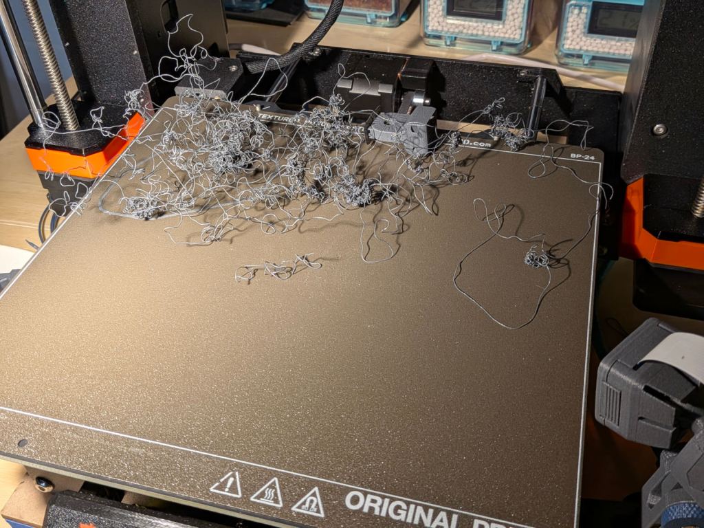
    (The camera in the lower right doesn’t yet record videos, so you must imagine what I saw.) I forgot capturing this screenshot:

    Prusa MK4 - Bird Nest - platform camera
    Prusa MK4 – Bird Nest – platform camera

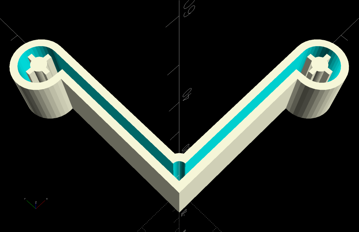
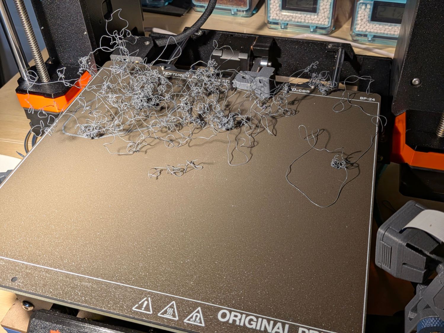
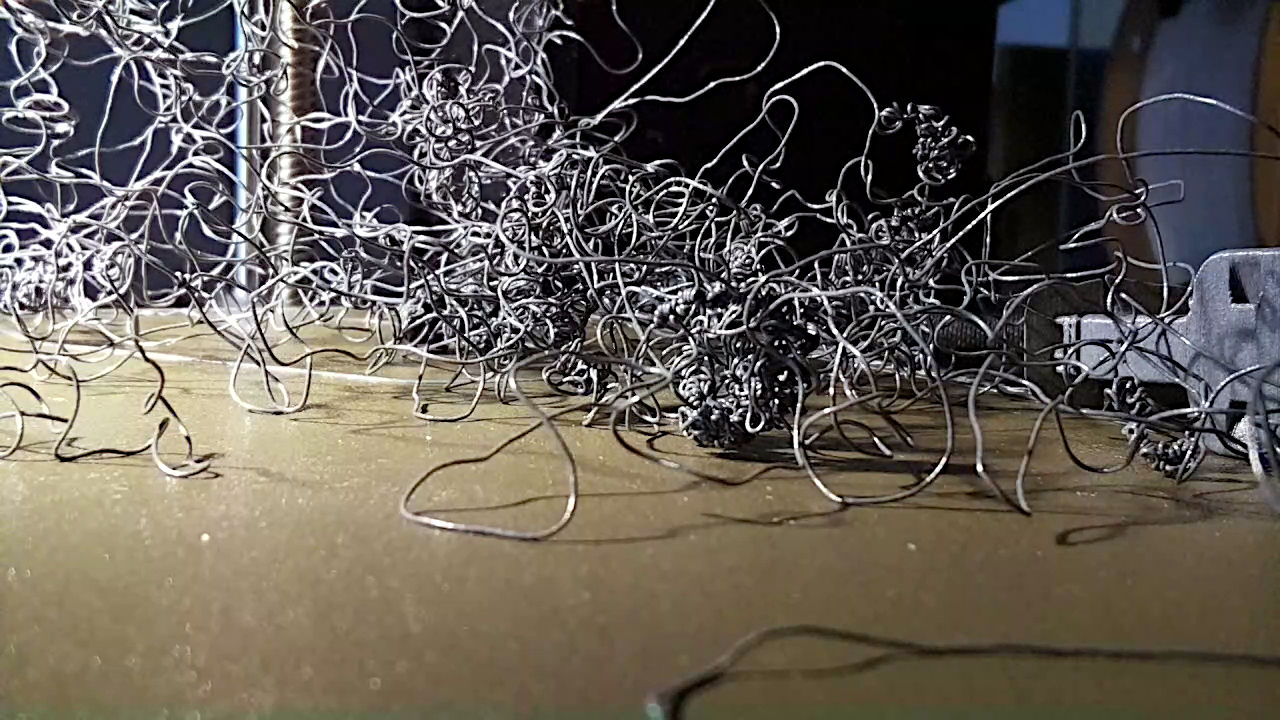
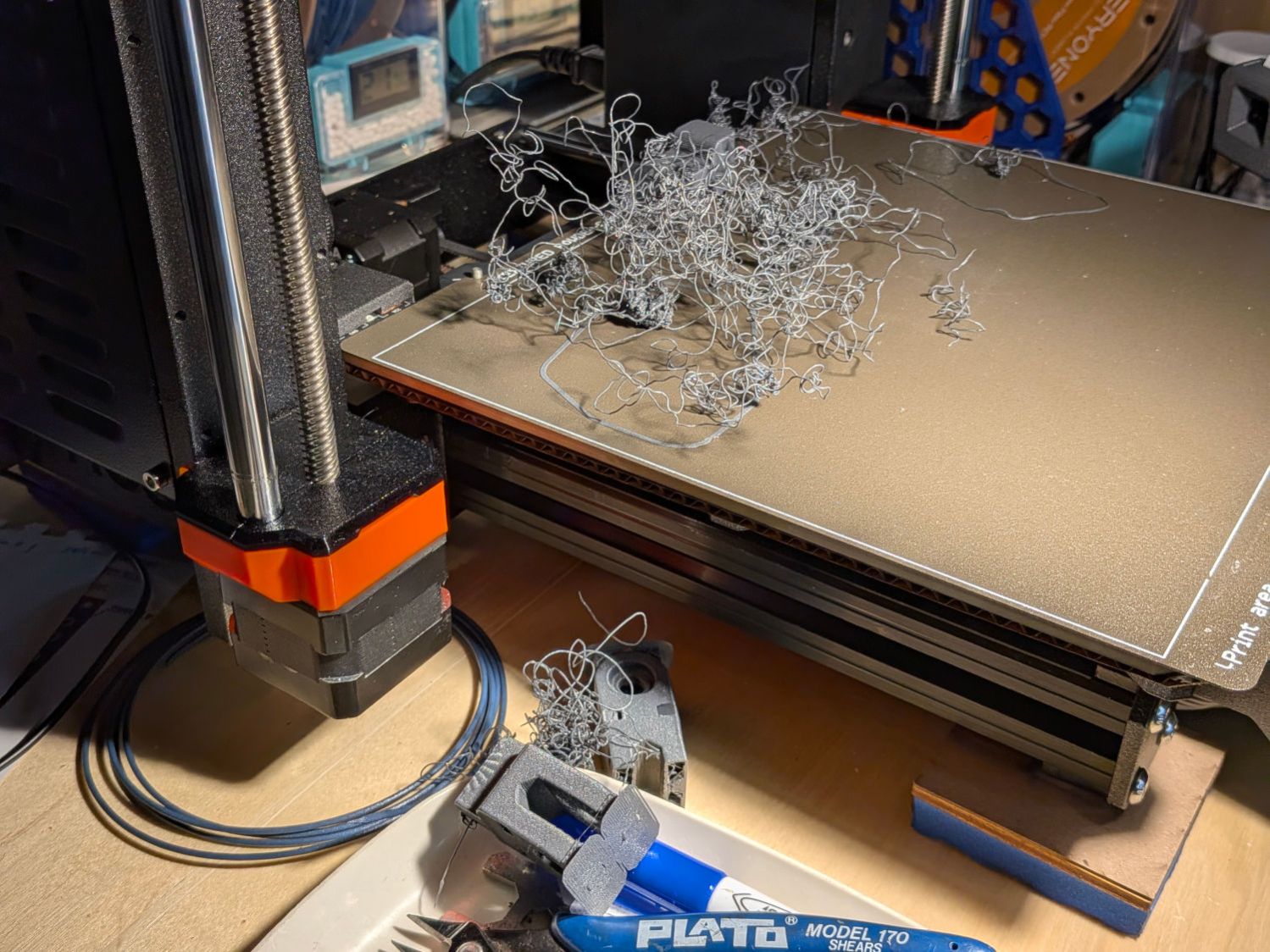
    The nozzle was busily adding to the tangle, so I shut the printer off and trotted to the Basement Shop™ to find two more parts lying dead on the workbench:

    Prusa MK4 - Bird Nest - B
    Prusa MK4 – Bird Nest – B

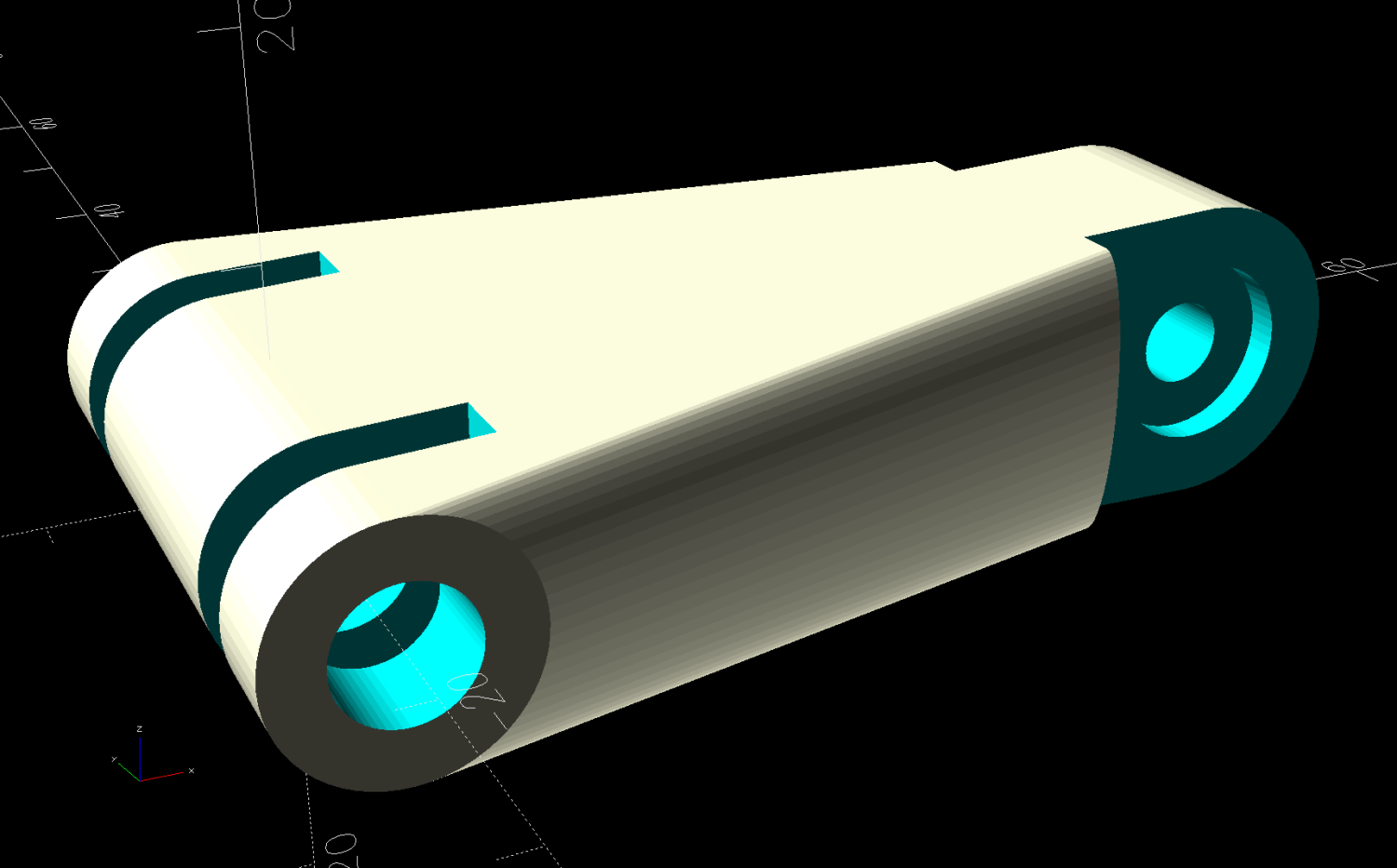
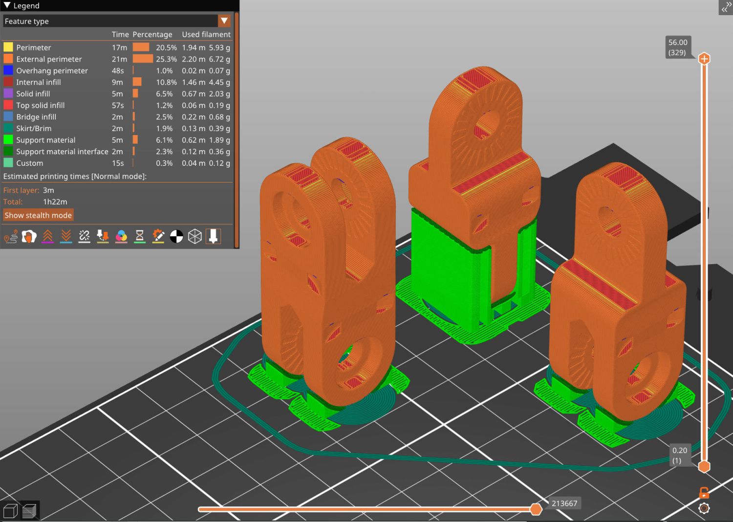
    This was entirely my fault, as I’d ignored PrusaSlicer’s warning about inadequate adhesion for the camera mount link standing in the corner:

    Prusa MK4 - Camera Mount Links - slicer preview
    Prusa MK4 – Camera Mount Links – slicer preview

    That’s the PrusaSlicer preview after adding a wider brim and painting more support structures on all three parts. Given larger footprints, the next attempt completed without drama, which is the normal outcome.

    Moral of the story: Tall skinny parts need more surface area on the platform than you think, even with excellent adhesion.

  • RPi Camera RTSP Setup

    RPi Camera RTSP Setup

    The rpicam.cfg file holding the parameters for the Raspberry Pi watching the Prusa MK 4 printer:

    bitrate=2000000 
    framerate=15
    timeout=0 
    nopreview= 
    codec=libav 
    libav-format=mpegts 
    width=1280
    height=720
    rotation=180
    roi=0.00,0.00,1.0,1.0
    hdr=auto
    

    The RPi camera for the wren nest is just taped to the window, but has a configuration providing a bigger picture:

    bitrate=2000000 
    framerate=15
    timeout=0 
    nopreview= 
    codec=libav 
    libav-format=mpegts 
    width=1920 
    height=1080 
    roi=0.00,0.00,1.0,1.0
    hdr=auto


    The useful pieces:

    • bitrate sets the average data rate, which may be too high for comfort outside your immediate LAN
    • framerate need not be as high as you think
    • nopreview prevents a preview picture while starting
    • width and height do the obvious thing, but don’t try to be too clever
    • roi picks the image from a specific part of the camera sensor, so you can adjust the image layout if you have a rigidly fixed camera
    • hdr doesn’t do anything for cheap RPi cameras

    Putting all the fiddly config in a file reduces the command line invocation to a mere jawbreaker:

    rpicam-vid --config rpicam.cfg -o - | cvlc stream:///dev/stdin --sout '#rtp{sdp=rtsp://:5886/wrens}' &
    

    Although you’d want to set that up to run automagically when the RPi starts up, for now I just fire it off as needed through an SSH session, with the ampersand letting it run after that terminal session closes.

    The RTSP port (5886) and stream (wrens) can be anything you like, which comes in handy when squirting streams through port-forwarded firewall pinholes using a router that cannot handle different external and internal port numbers.

    Useful background info:

  • Window Mount for Bamboo Bee Tunnel Nests

    Window Mount for Bamboo Bee Tunnel Nests

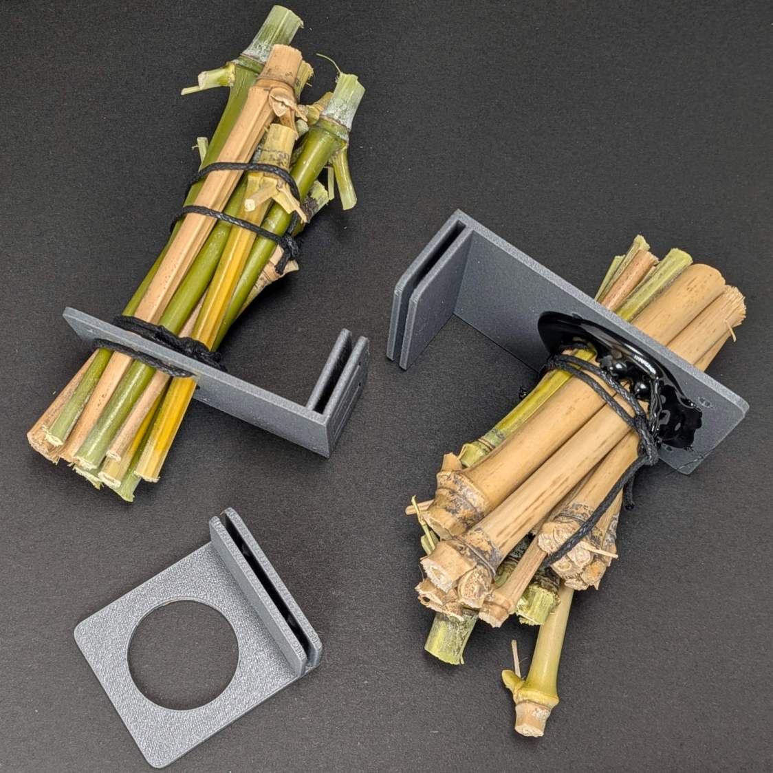
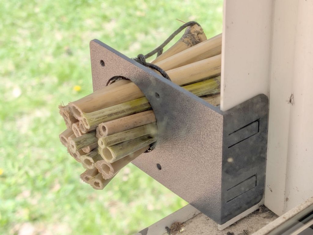
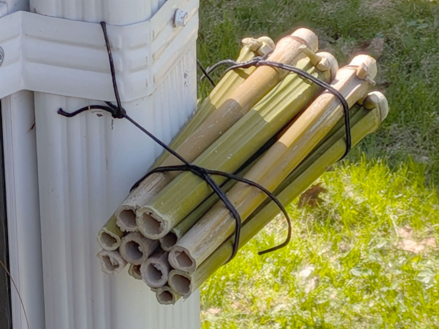
    Mary suggested converting wild bamboo up the hill into tunnel nests (per a xerces.org paper) for native bees buzzing around flowers in the yard, so:

    Bee Tunnel Nest - downspout installation
    Bee Tunnel Nest – downspout installation

    I hung bundles of larger tubes in trees out back, in hopes of attracting huge carpenter bees.

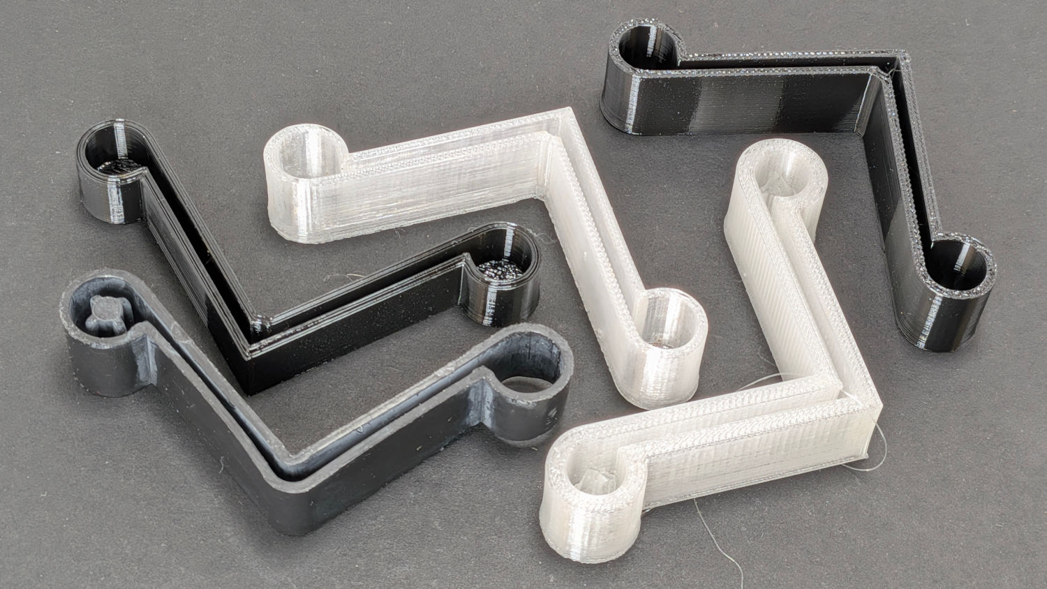
    3D printed mounts hold smaller bundles on the windows to let us keep an eye on the proceedings:

    Bee Tunnel Nest Mount - installed-]
    Bee Tunnel Nest Mount – installed

    Which look better when not seen though two layers of glass in desperate need of Spring Cleaning:

    Bee Tunnel Nest Mounts
    Bee Tunnel Nest Mounts

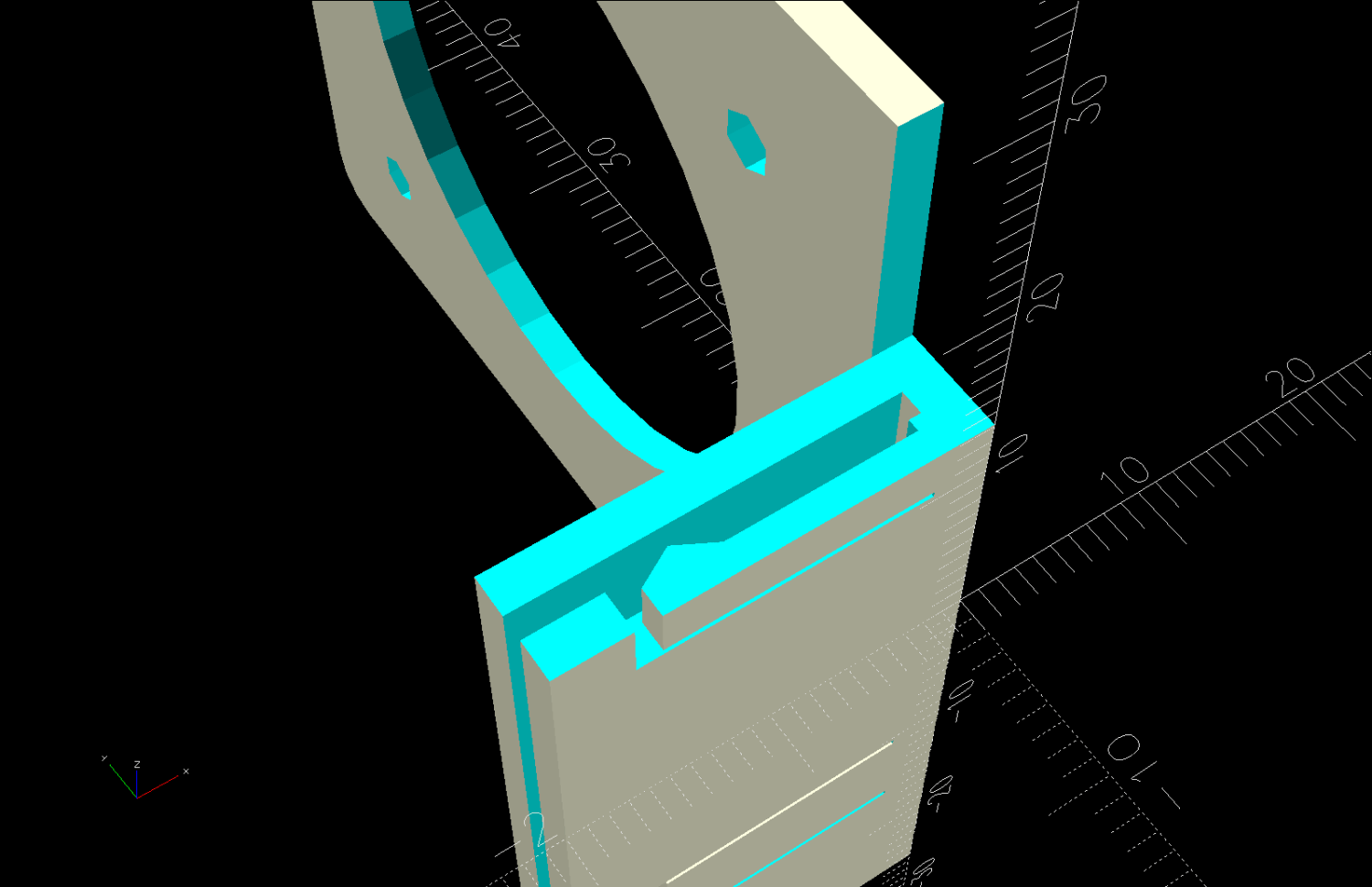
    The tabs provide a bit of pressure to hold the mounts in place, although I don’t know if they have enough springiness or will survive contact with the elements:

    Bee Tunnel Nest Mount - tab section - solid model
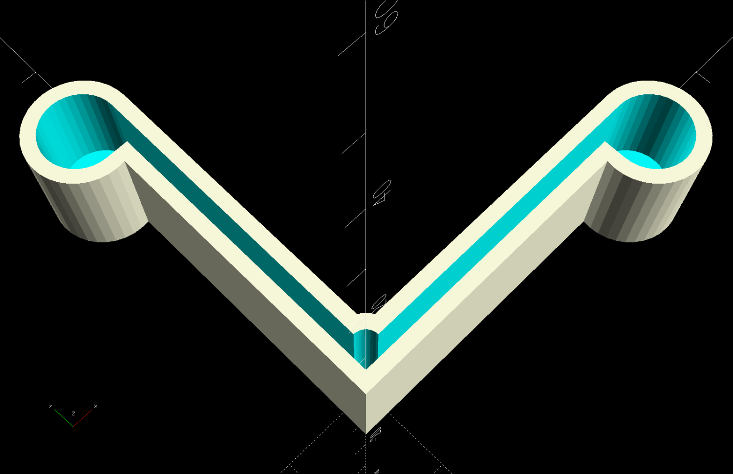
    Bee Tunnel Nest Mount – tab section – solid model

    The key advantage of not building bigger bee motels: these little bundles don’t need annual cleaning / maintenance and will eventually fall apart.

    If the bees find them suitable, more power to ’em!

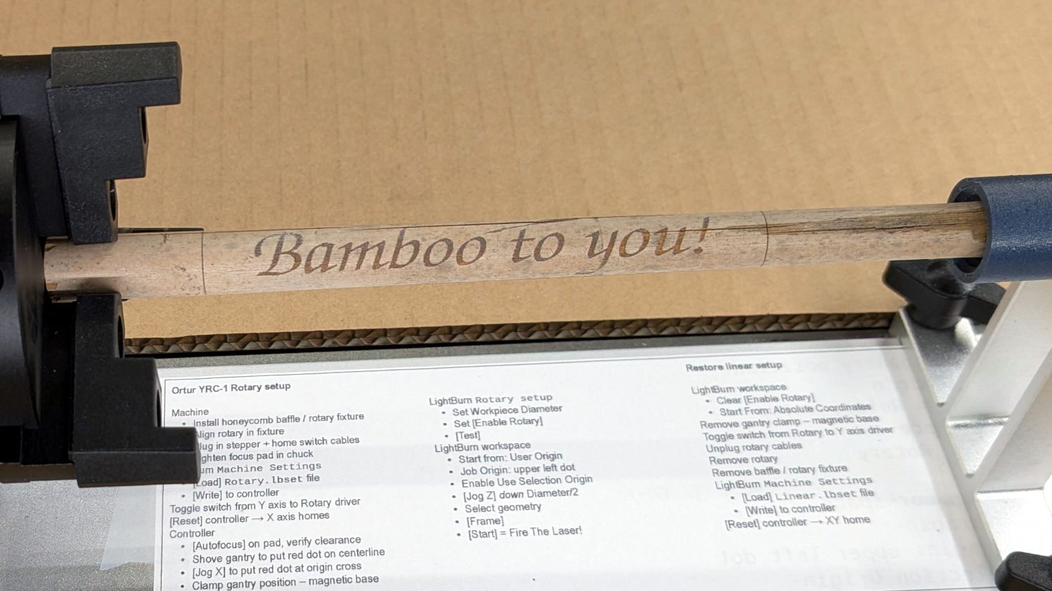
    And I realized the cut-off ends fit in the rotary. Witticisms engraved on bamboo could become the New Hotness:

    Laser engraved bamboo
    Laser engraved bamboo

    Stipulated: I’m barely half-right about being a wit …

    The OpenSCAD source code as a GitHub Gist:

    // Bee Tunnel Nest Mount
    // Ed Nisley – KE4ZNU
    // 2026-04-26
    include <BOSL2/std.scad>
    Layout = "Show"; // [Build,Show,Window,Bundle,Tabs]
    BundleOD = 35.0;
    BundleOffset = 0.0;
    SlotDepth = 18.0;
    SlotGap = 1.2;
    /* [Hidden] */
    HoleWindage = 0.2;
    Protrusion = 0.01;
    NumSides = 3*2*4;
    Clearance = 0.3;
    //$fn=NumSides;
    WallThick = 2.0;
    MountHeight = 1.5*BundleOD;
    MountWidth = 1.5*BundleOD + BundleOffset;
    ClipOA = [SlotDepth + WallThick,SlotGap + 2*WallThick,MountHeight];
    BundleCtr = [-WallThick/2,ClipOA.y + MountWidth/2 + BundleOffset/2,MountHeight/2];
    TabOA = [0.7*SlotDepth,5.0,0.7*WallThick];
    TabOffset = 0.2*SlotDepth;
    TabOC = MountHeight/2;
    TabClearance = [4*Clearance,0,Clearance];
    //—–
    // Define things
    module BundleMount() {
    difference() {
    cuboid([WallThick,MountWidth + ClipOA.y,MountHeight],
    rounding=3.0,edges=[TOP+BACK,BOTTOM+BACK],anchor=FRONT+RIGHT);
    back(BundleCtr.y)
    xcyl(3*WallThick,d=BundleOD);
    for (j=[-1,1],k=[-1,1])
    translate([BundleCtr.x,j*BundleOD/2 + BundleCtr.y,k*BundleOD/2])
    xcyl(3*WallThick,d=3.0,$fn=6);
    }
    }
    module WindowMount() {
    difference() {
    cuboid(ClipOA,rounding=3.0,edges=[TOP+LEFT,BOTTOM+LEFT],
    anchor=FRONT+RIGHT);
    left(WallThick) back(WallThick)
    cuboid([2*SlotDepth,SlotGap,2*MountHeight],anchor=FRONT+RIGHT);
    for (k=[-1,1])
    translate([-(ClipOA.x – TabOffset),-Protrusion,k*TabOC/2])
    cuboid([TabOA.x + TabClearance.x,WallThick + 2*Protrusion,TabOA.y + 2*TabClearance.z],anchor=FRONT+LEFT);
    }
    }
    module Tabs() {
    for (j=[-1,1])
    fwd(j*TabOC/2)
    cuboid(TabOA,anchor=BOTTOM+LEFT) position(LEFT+TOP)
    prismoid(size1=[3*SlotGap,TabOA.y],size2=[0,TabOA.y/2],
    h=(WallThick – TabOA.z) + SlotGap/3,anchor=BOTTOM+LEFT);
    }
    module Assembly() {
    union() {
    BundleMount();
    WindowMount();
    left(ClipOA.x – TabOffset – TabClearance.x)
    xrot(-90)
    Tabs();
    }
    }
    //—–
    // Build things
    if (Layout == "Bundle") {
    BundleMount();
    }
    if (Layout == "Window") {
    WindowMount();
    }
    if (Layout == "Tabs") {
    Tabs();
    }
    if (Layout == "Show") {
    Assembly();
    }
    if (Layout == "Build") {
    yrot(90)
    Assembly();
    }
  • Steel Shelving Foot Pads

    Steel Shelving Foot Pads

    All of the plastic pads vanished from the legs of a steel shelf unit somewhere along the way:

    Steel Shelving Foot Pads - post shape
    Steel Shelving Foot Pads – post shape

    Some solid modeling produced a suitable replacement shape:

    Steel Shelving Foot Pads - no pegs - solid model
    Steel Shelving Foot Pads – no pegs – solid model

    A few prototypes (with a broken OEM version at lower left) matched the model to reality:

    Steel Shelving Foot Pads - test pieces
    Steel Shelving Foot Pads – test pieces

    They’re natural & black TPU, because the job requirements include being tough and bendy:

    Steel Shelving Foot Pads - installed
    Steel Shelving Foot Pads – installed

    Each one takes about half an hour to ooze from the Makergear M2, so after verifying the prototype’s fit, printing four at a time makes sense:

    Steel Shelving Foot Pads - slicer
    Steel Shelving Foot Pads – slicer

    The OpenSCAD code includes the pegs in the original and the first chunky TPU version:

    Steel Shelving Foot Pads - with pegs - solid model
    Steel Shelving Foot Pads – with pegs – solid model

    It turns out they don’t have any obvious benefit in a TPU pad, so they’re disabled in the code.

    Now those legs sit firmly on the floor and the post tops aren’t nearly so threatening.

    The OpenSCAD source code as a GitHub Gist:

    // Steel Shelf Foot Pads
    // Ed Nisley – KE4ZNU
    // 2026-04-18
    include <BOSL2/std.scad>
    /* [Hidden] */
    Protrusion = 0.01;
    NumSides = 4*9;
    $fn=NumSides;
    Clearance = 1.0/2;
    WallThick = 1.0 + Clearance;
    BaseThick = 2.0;
    PadOAH = BaseThick + 11.0;
    RollID = 6.4;
    RollOD = 7.4 + Clearance;
    RollOffset = 29.5;
    LegThick = 0.5 + 2*Clearance;
    Pins = [
    [-(RollOD/2), (RollOffset + RollOD/2),0],
    [(RollOffset + RollOD/2), -(RollOD/2),0],
    ];
    //—–
    // Build things
    union() {
    difference() {
    union() {
    for (pin = Pins)
    translate(pin)
    cyl(PadOAH,d=RollOD + 2*WallThick,anchor=BOTTOM);
    translate([-(WallThick + LegThick),-(WallThick + LegThick),0])
    cuboid([2*WallThick + LegThick,WallThick + LegThick + Pins[0].y,PadOAH],
    anchor=BOTTOM+LEFT+FRONT);
    translate([-(WallThick + LegThick),-(WallThick + LegThick),0])
    cuboid([WallThick + LegThick + Pins[1].x,2*WallThick + LegThick,PadOAH],
    anchor=BOTTOM+LEFT+FRONT);
    cyl(PadOAH,r=(WallThick + LegThick),anchor=BOTTOM);
    }
    up(BaseThick)
    cyl(PadOAH,r=LegThick,anchor=BOTTOM);
    up(BaseThick)
    for (pin = Pins)
    translate(pin)
    cyl(PadOAH,d=RollOD,anchor=BOTTOM);
    up(BaseThick) {
    translate(Pins[0])
    cuboid([RollOD/2,RollOD/2,PadOAH],anchor=BOTTOM+LEFT+BACK);
    translate(Pins[1])
    cuboid([RollOD/2,RollOD/2,PadOAH],anchor=BOTTOM+RIGHT+FRONT);
    }
    up(BaseThick) {
    fwd(LegThick)
    cuboid([LegThick,Pins[0].y + LegThick,PadOAH],anchor=BOTTOM+RIGHT+FRONT);
    left(LegThick)
    cuboid([Pins[1].x + LegThick,LegThick,PadOAH],anchor=BOTTOM+LEFT+BACK);
    }
    }
    if (false)
    for (pin = Pins)
    translate(pin) {
    cyl(PadOAH,d=RollID/2,anchor=BOTTOM);
    for (a = [0,90])
    zrot(a)
    cuboid([1.0,RollID – 2*Clearance,PadOAH],anchor=BOTTOM);
    }
    }

  • Punched Cards: Summary

    Punched Cards: Summary

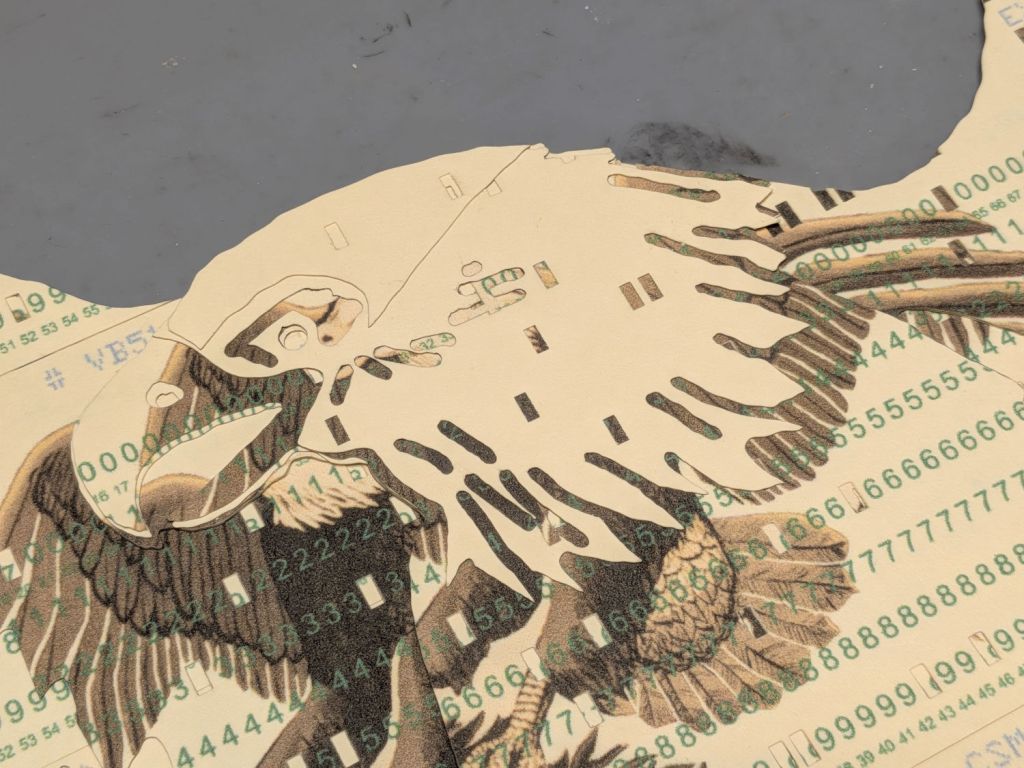
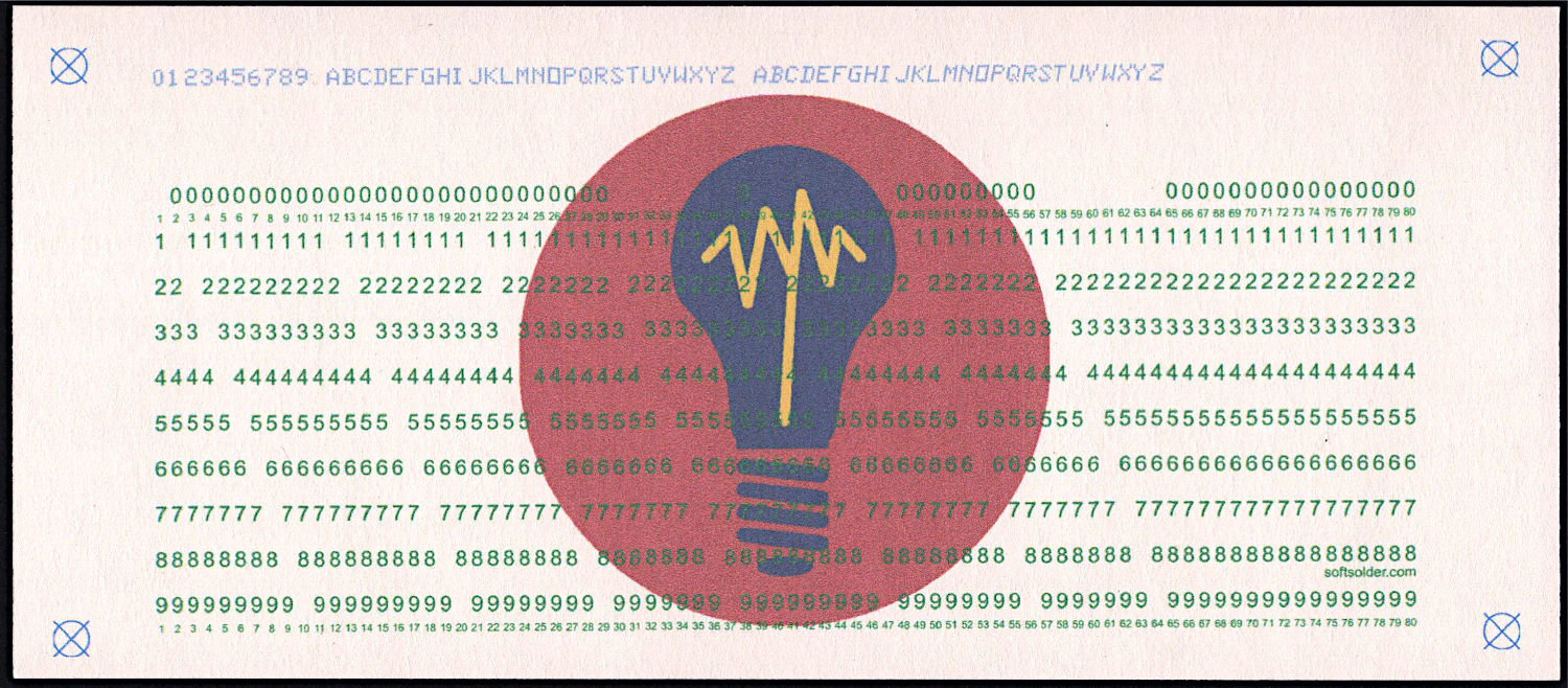
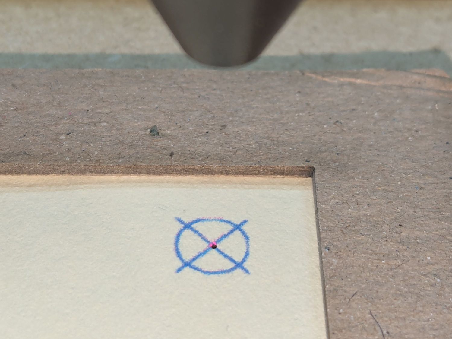
    At last, I can make plausible-looking punched cards:

    Test Card 3 - punched
    Test Card 3 – punched

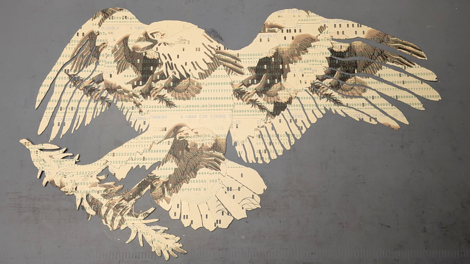
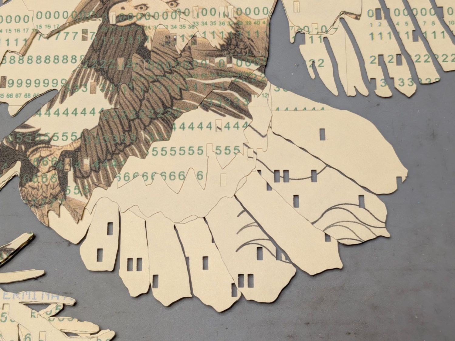
    Then chop most of them up to make a layered eagle:

    Apollo Eagle - V3 - overview
    Apollo Eagle – V3 – overview

    Back in the beginning, the grand overview explained the card production process, but now I can pull all the blog posts into a more coherent story.

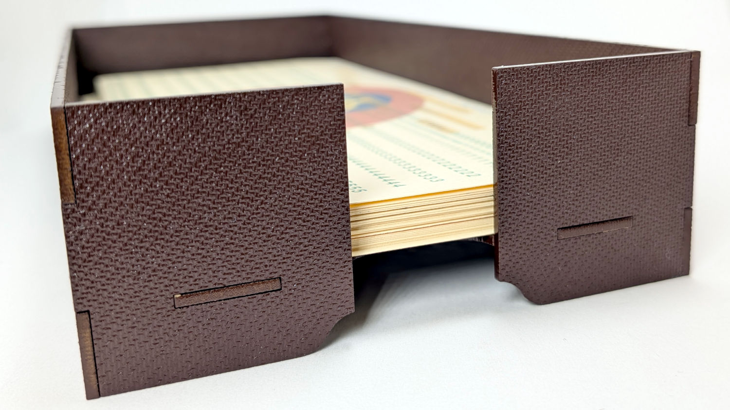
    Start by making trays to hold the 1/3 Letter sized printed cards and the final cut cards. A coat of paint improves the result:

    Card Storage Tray - front
    Card Storage Tray – front

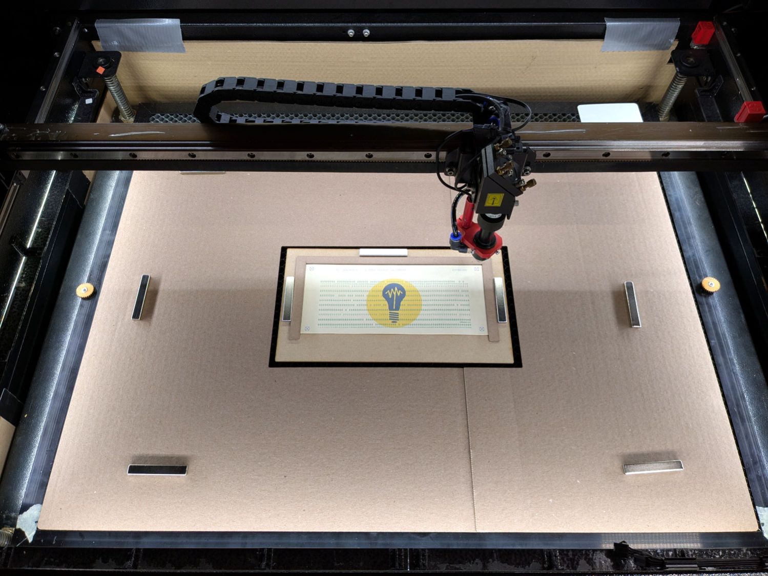
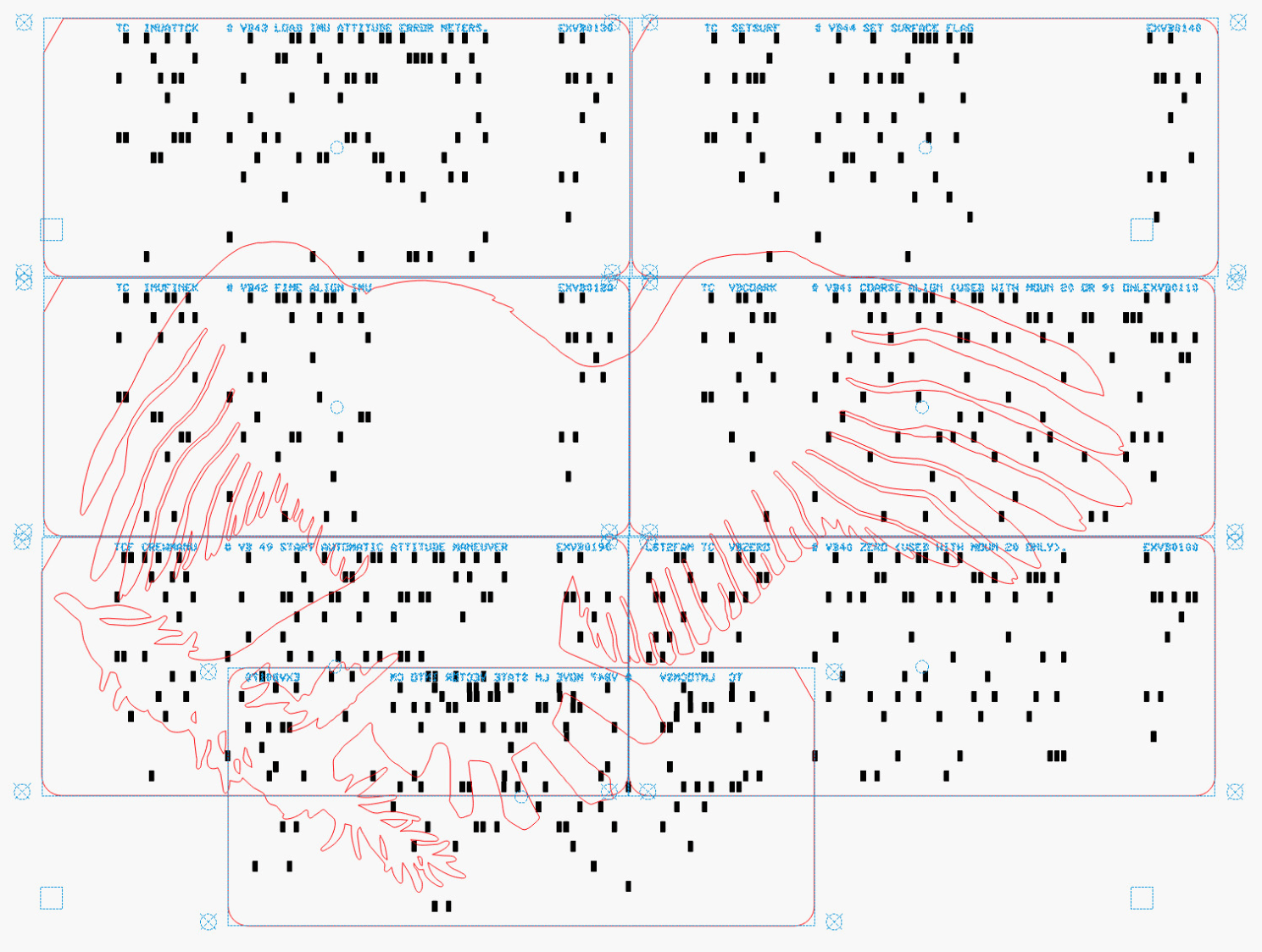
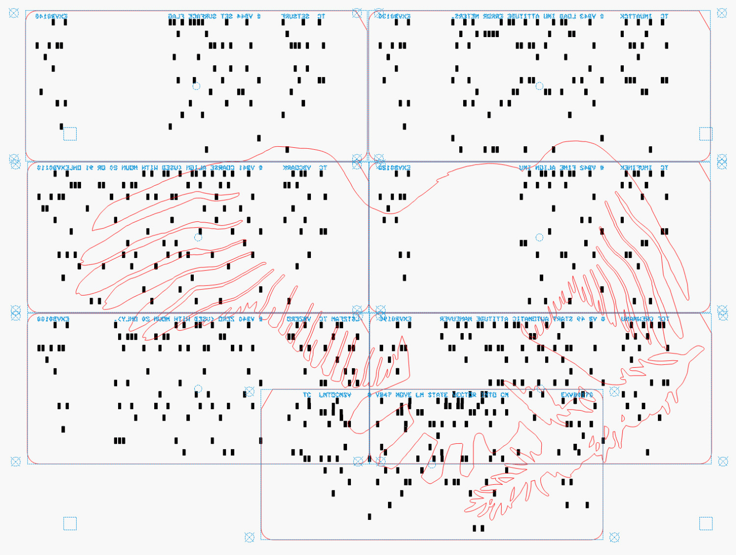
    Then make a fixture to position the 1/3 Letter printed cards in the laser and a simple cover for the honeycomb to direct the air flow:

    Punched cards - laser fixture overview
    Punched cards – laser fixture overview

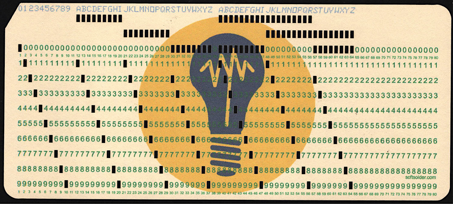
    The current versions of the Python program to convert a line of text into the SVG images required to print and punch the cards, plus the Bash scripts handling all the command line parameters, are now in a single GitHub Gist . I used the source code from the Apollo 11 CSM AGC for historic reasons.

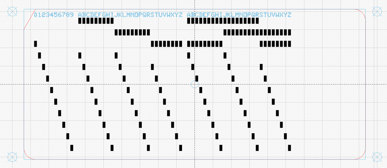
    The Bash scripts invoke the Python program twice to produce both the printed layout:

    Punched Cards - test card - printed
    Punched Cards – test card – printed

    And “punched” holes surrounded by the perimeter cut for the laser:

    Test Card 3 - LightBurn layout
    Test Card 3 – LightBurn layout

    The Python program handles translation from the ASCII (really Unicode) character set into the EBCDIC punched hole layout. Because LightBurn and Inkscape handle SVG scaling differently, the script sorts that out.

    Because my printer produces slightly off-size printed images, the script uses Inkscape to convert the SVG into a PNG, then downscales the image by a few percent (a different percent on each axis). It composites the card logo onto the PNG and slams the result onto a Letter page in the proper place to hit the 1/3 Letter sheets.

    Aligning the targets printed on the cards with the corresponding target positions in the laser SVG requires careful fixture skootching:

    Red dot vs printed target vs laser spot alignment
    Red dot vs printed target vs laser spot alignment

    A batch file feeds the laser SVGs into LightBurn, so the process boils down to a few mouse clicks per card.

    With a tray full of finished cards in hand, I converted the eagle from the Apollo 11 mission patch into a set of outlines:

    Apollo 11 Patch - eagle layers
    Apollo 11 Patch – eagle layers

    Each of those outlines defines the shape of a layer cut from those printed cards:

    Apollo Eagle - V3 - head
    Apollo Eagle – V3 – head

    Not gonna lie: it took serious effort to cut up those cards.

    Each layer has a specific set of cards chosen to put the holes in the proper place while hiding the card joints:

    Apollo Eagle - V4 Layer 1 cards
    Apollo Eagle – V4 Layer 1 cards

    Mirroring the layout helped me arrange the cards correctly while taping the back side of the joints with book repair tape:

    Apollo Eagle - V4 Layer 1 cards - mirrored
    Apollo Eagle – V4 Layer 1 cards – mirrored

    Slap a sheet of cards on the laser platform, align it to the layer’s outline, Fire The Laser, and stack up the results:

    Apollo Eagle - V3 - tail
    Apollo Eagle – V3 – tail

    I used Elmer’s All Purpose Glue Stick to hold the layers together, figuring if it’s good enough for kindergartners it’s good enough for me.

    And that’s all there is to it …

  • Gridfininty Tape Dispenser

    Gridfininty Tape Dispenser

    A Gridfinity Tape Dispenser holds a roll of book repair tape:

    Gridfinity Tape Dispenser - overview
    Gridfinity Tape Dispenser – overview

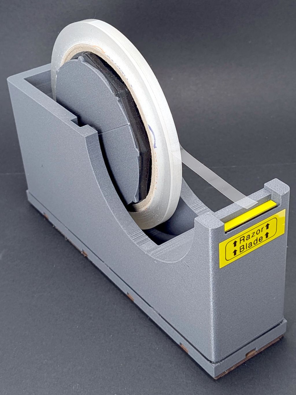
    The perspective makes the dispenser look chonkier than it really is.

    A wrap of black silicone tape around the spool embiggens it for a snug fit inside the tape core. A casual inspection of other tapes suggest enlarging the spool by a few percent would help, but it’s Good Enough™ as-is.

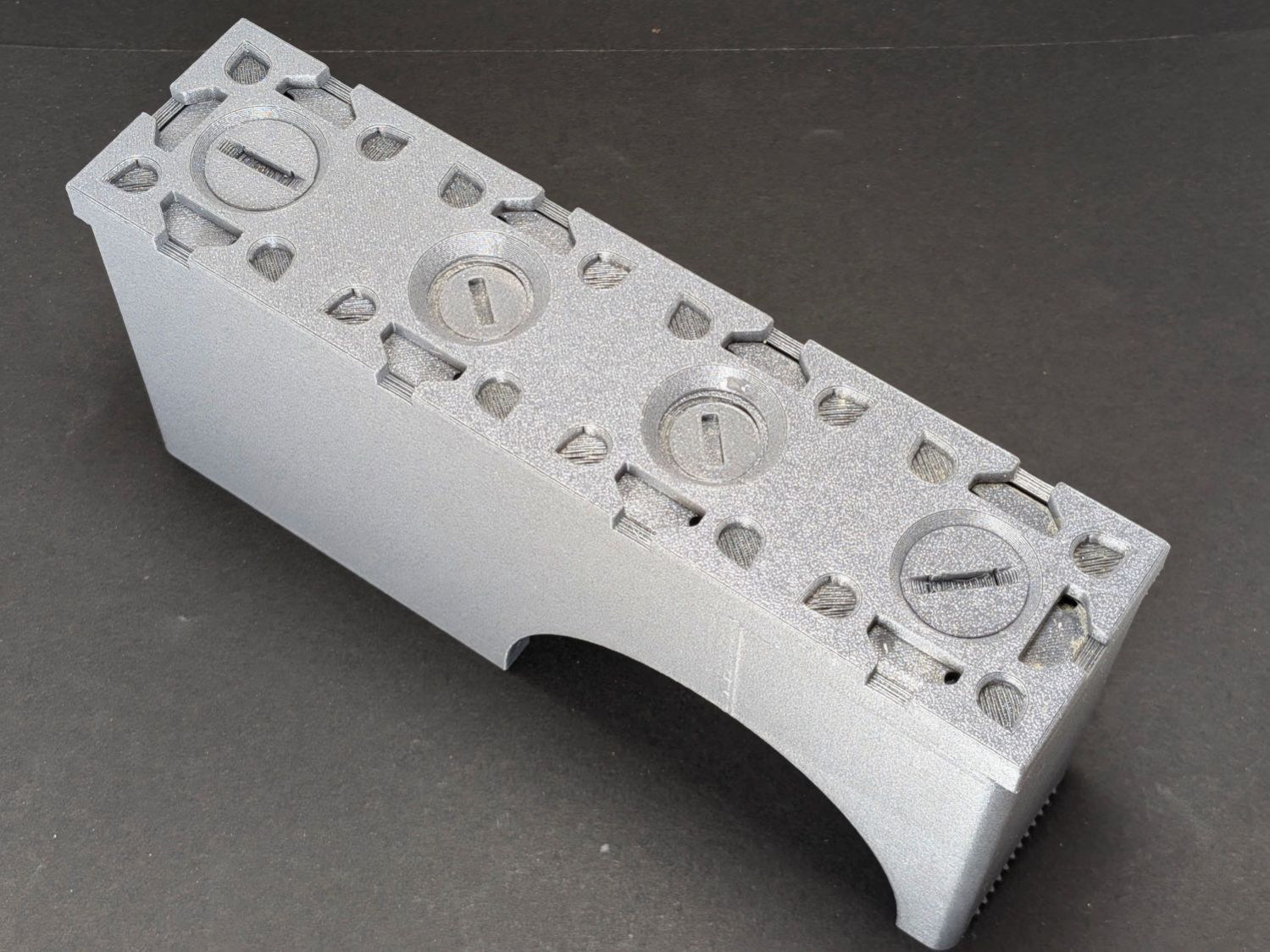
    The two end thumbscrews fasten the 4×1 Gridfinity baseplate to the dispenser; both from Gridfinity Refined:

    Gridfinity Tape Dispenser - baseplate
    Gridfinity Tape Dispenser – baseplate

    If I had my wits about me, I’d have used a nicely contrasting color for the baseplate, but it is what it is.

    Although they’re called “thumbscrews”, the slot is sized for a US quarter (or cart coin).

    An OpenSCAD one-liner produces an SVG model of the baseplate:

    projection(cut=true) import("Grid 4x1.stl");
    

    Import SVG into LightBurn, delete the magnet pockets, and Fire The Laser on some EVA foam:

    Gridfinity Tape Dispenser - foam base
    Gridfinity Tape Dispenser – foam base

    A layer of 3M 300LSE tape holds the foam in place, because neither side sticks well to the goo on a craft adhesive sheet due to their low surface energy. I stuck an oversize rectangle to the foam with the thin adhesive side before cutting, which required a second pass at higher speed.

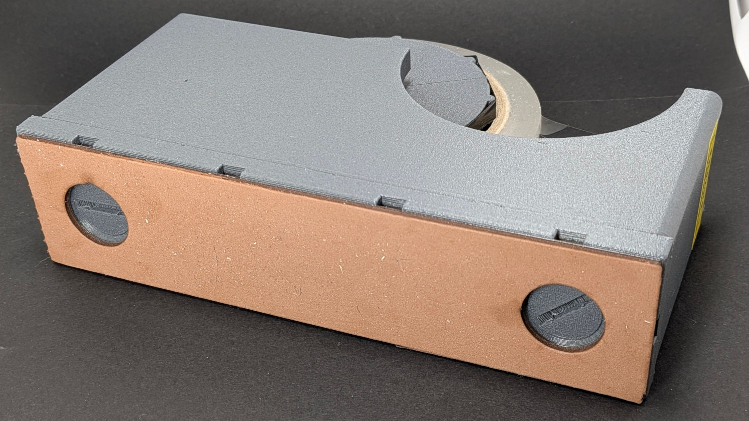
    The thumbscrews also close off the holes in the dispenser bottom through which I poured 275 g = 10 oz of sand for better traction. Steel shot is reputed to be Even Better, although most of the BBs are in the long-arm weight.

    The dispenser model includes a printed serrated blade which works as poorly as the author suggested. A length snapped from an ancient Strombecker 4-I (“four eye”) blade in the Box o’ Big X-Acto Blades fits perfectly, works wonderfully well, and is sufficiently inconspicuous to warrant the warning label. An X-Acto #26 Whittling Blade would probably snap down equally well.

  • LED Garage Light: Desk Lamp Upcycling

    LED Garage Light: Desk Lamp Upcycling

    One of the heatsink panels from the defunct LED garage light now casts a uniform warm-white glow on my desk:

    LED Garage Light - desk light
    LED Garage Light – desk light

    A PCB intended as a lithium battery charger serves as a constant-current supply:

    LED Garage Light - constant current driver
    LED Garage Light – constant current driver

    The three trimpots, from left to right:

    • Constant-voltage limit adjustment
    • Full-charge current setpoint (irrelevant here)
    • Constant-current limit adjustment

    The as-received trimpot settings will be wildly inappropriate for a nominal 10 W COB LED array, so:

    • Connect the output to about 10 Ω of power resistors
    • … with an ammeter in series
    • Connect the input to a 12 VDC / 1-ish A wall wart
    • Adjust the output voltage to 10 V
    • Adjust the output current to 900 mA

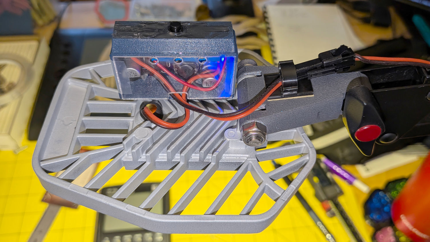
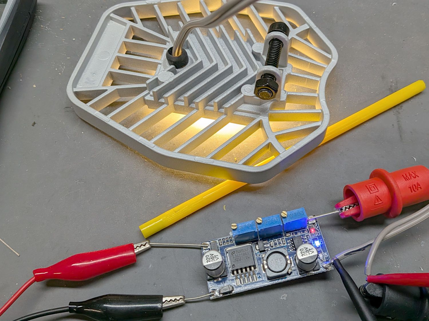
    As long as the voltage limit is over about 10 V, it will (likely) never matter, as the LED forward drop doesn’t vary much with temperature. Setting it to something sensible keeps it out of the way.

    The middle trimpot apparently sets a voltage for a comparator to light an LED when the battery current drops below that level as it reaches full charge.

    Although the regulator touts its high efficiency, it does run hot and a heatsink seemed in order:

    LED Garage Light - heatsink
    LED Garage Light – heatsink

    Stipulated: the fins run the wrong way and it’s sitting in the updraft from the main heatsink. It’s Good Enough™.

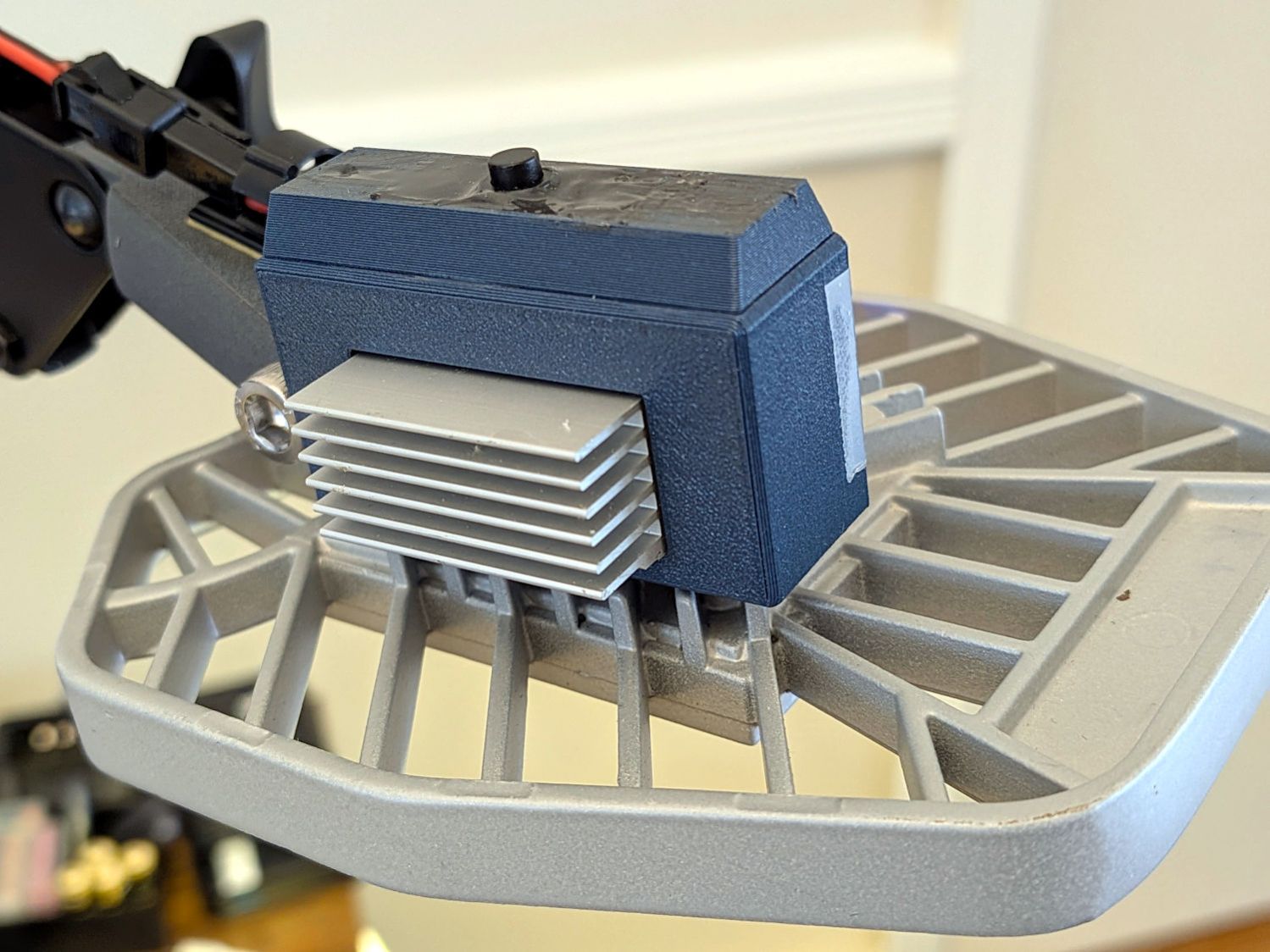
    The switch on the top comes from the collection of flashlight tailcap switches and controls the 12 V input power. It’s buried up to its button in a generous dollop of JB Kwik epoxy, which seemed the least awful way to get that done.

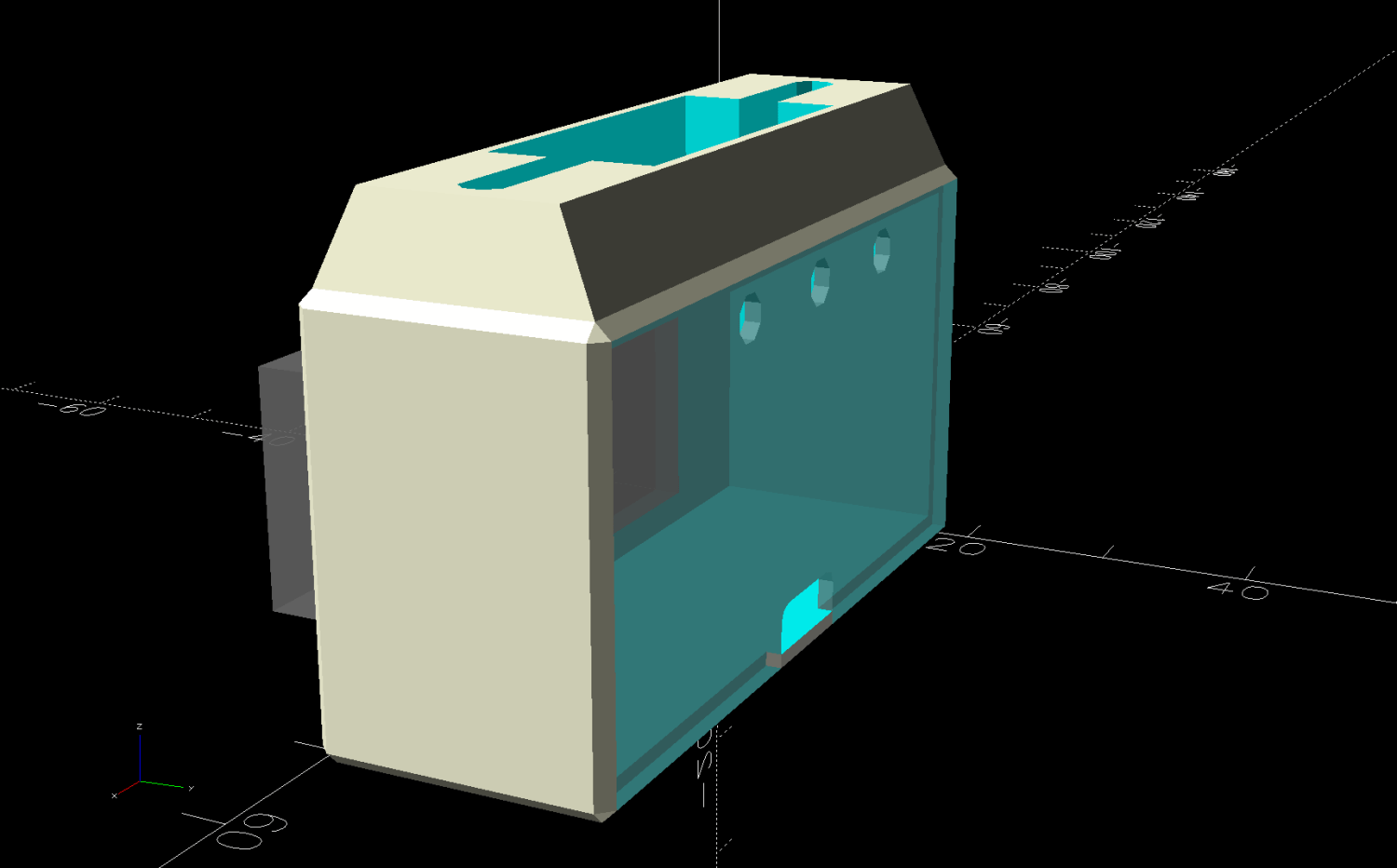
    The solid model looks about like you’d expect:

    LED Lamp Driver case - switch housing - show solid model
    LED Lamp Driver case – switch housing – show solid model

    The OpenSCAD code exports the (transparent) lid as an SVG so I can import it into LightBurn and laser-cut some thin acrylic. Two tape snippets hold the lid in place pending more power-on hours, after which I’ll apply a few dots of cyanoacrylate adhesive and call it done.

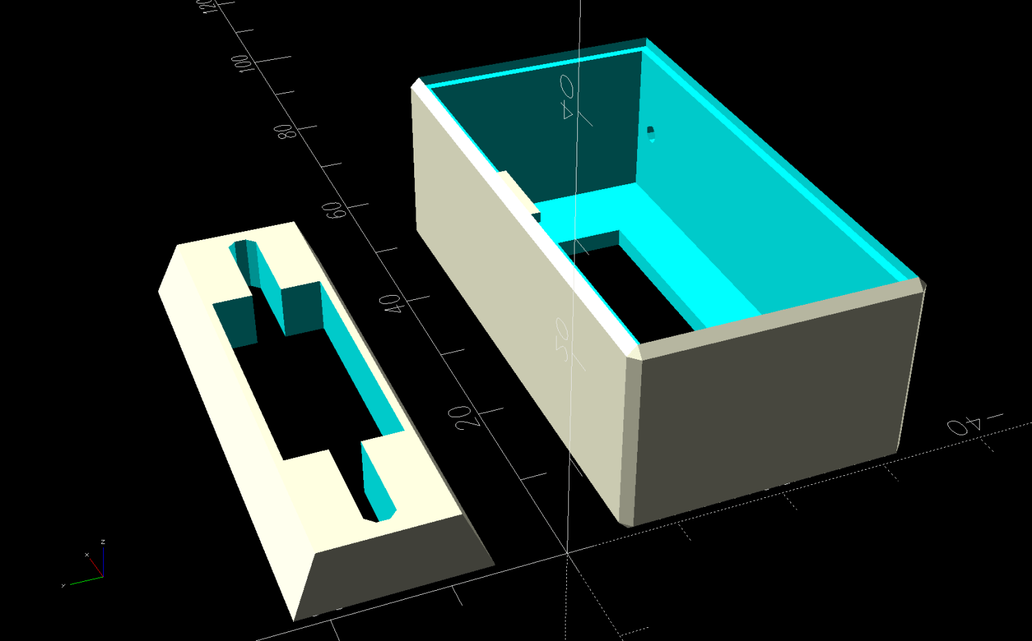
    The case builds in two pieces that glue together to avoid absurd support structures:

    LED Lamp Driver case - switch housing - build solid model
    LED Lamp Driver case – switch housing – build solid model

    A 3D printed adapter goes between the desk lamp arm and the lamp heatsink bolt:

    LED Lamp Driver case - arm adapter - solid model
    LED Lamp Driver case – arm adapter – solid model

    The OpenSCAD source code files for the case and adapter arm as a GitHub Gist:

    // LED Lamp arm adapter
    // Ed Nisley – KE4ZNU
    // 2026-03-18
    include <BOSL2/std.scad>
    Layout = "Adapter"; // [Show,Build,ArmClamp,SinkClamp,Adapter]
    /* [Hidden] */
    HoleWindage = 0.2;
    Protrusion = 0.01;
    Gap = 5.0;
    $fn=5*3*4;
    HoleOC = 45.0;
    ArmRad = 7.5;
    ArmWidth = 11.3;
    SinkOD = 11.5;
    SinkThick = 3.2;
    SinkOC = 20.0;
    ClampThick = 5.0; // outside sink, watch thinning due to hull()
    // Define things
    // Screw & bushings in lamp arm bracket
    // … over-long bushings to prevent coincident surfaces
    module ArmClamp() {
    BushingThick = 1.5;
    BushingOD = 9.0;
    union() {
    ycyl(ArmWidth,d=4.0 + HoleWindage); // central M4 screw
    for (j=[-1,1]) {
    back(j*(ArmWidth – BushingThick + Protrusion)/2)
    ycyl(BushingThick + Protrusion,d=BushingOD);
    back(j*(ArmWidth + 10)/2)
    cuboid([2*ArmRad,10,2*ArmRad]);
    }
    }
    }
    module SinkClamp() {
    union() {
    ycyl(2*SinkOC,d=6.0 + HoleWindage); // central M6 screw
    for (j=[-1,1])
    back(j*SinkOC/2) {
    ycyl(SinkThick + Protrusion,d=SinkOD);
    cuboid([SinkOD,SinkThick + Protrusion,2*SinkOD]);
    }
    }
    }
    module Adapter() {
    difference() {
    hull() {
    right(HoleOC)
    ycyl(ArmWidth,r=ArmRad);
    ycyl(SinkOC + SinkThick + 2*ClampThick,d=SinkOD);
    }
    right(HoleOC)
    ArmClamp();
    SinkClamp();
    }
    }
    // Build it
    if (Layout == "ArmClamp")
    ArmClamp();
    if (Layout == "SinkClamp")
    SinkClamp();
    if (Layout == "Adapter")
    Adapter();
    if (Layout == "Build")
    up(SinkOD/2)
    yrot(-atan((ArmRad – SinkOD/2)/HoleOC))
    Adapter();
    // LED Constant-current driver case
    // Ed Nisley – KE4ZNU
    // 2026-03-15
    include <BOSL2/std.scad>
    Layout = "Show"; // [Show,Build,Case,Lid,LidSVG,Switch]
    /* [Hidden] */
    ThreadThick = 0.2;
    HoleWindage = 0.2;
    Protrusion = 0.01;
    Gap = 5.0;
    WallThick = 1.8;
    TapeThick = 1.5;
    DriverOA = [48.5,13.5 + TapeThick,23.5]; // PCB forward Y, pots along top to rear
    SinkOA = [31.5,12.0,15.5]; // fins forward
    SinkOffset = [(DriverOA.x – SinkOA.x)/2,0,2.0]; // from lower left front corner of PCB
    AdjPots = [14,24,34]; // screwdriver adjust offsets
    AdjOD = 3.0; // … access hole dia
    CaseOA = DriverOA + [2*WallThick,2*WallThick,2*WallThick];
    echo(CaseOA=CaseOA);
    LidOA = [CaseOA.x – WallThick,CaseOA.z – WallThick,1.0];
    Cables = [8.0,3.0 + WallThick/2,LidOA.z];
    SwitchWireOC = DriverOA.x – 6.0;
    SwitchCapBase = [DriverOA.x + WallThick,DriverOA.y + WallThick];
    SwitchCapTop = [DriverOA.x,12.0];
    SwitchCavity = [25.0,10.5,5.5];
    // Define things
    module Lid() {
    difference() {
    cuboid(LidOA,anchor=BOTTOM+FWD+LEFT);
    for (i = AdjPots)
    translate([i,LidOA.y – AdjOD/2 – WallThick/2,-Protrusion])
    cyl(LidOA.z + 2*Protrusion,d=AdjOD,anchor=BOTTOM,$fn=8,spin=180/8);
    translate([LidOA.x/2,-Protrusion,-Protrusion])
    cuboid(Cables + [0,Protrusion,2*Protrusion],rounding=1.0,edges=[BACK+LEFT,BACK+RIGHT],anchor=BOTTOM+FWD);
    }
    }
    module SwitchBox() {
    difference() {
    prismoid(SwitchCapBase,SwitchCapTop,SwitchCavity.z,anchor=BOTTOM);
    down(Protrusion)
    cuboid(SwitchCavity + [0,0,2*Protrusion],anchor=BOTTOM);
    hull()
    for (i=[-1,1])
    right(i*SwitchWireOC/2)
    zcyl(CaseOA.z,d=3.0,$fn=8,spin=180/8);
    }
    }
    module Case() {
    difference() {
    cuboid(CaseOA,chamfer=WallThick/2,anchor=BOTTOM+FWD+LEFT);
    translate([WallThick,WallThick + Protrusion,WallThick])
    cuboid(DriverOA + [0,WallThick + Protrusion,0],anchor=BOTTOM+FWD+LEFT);
    translate(SinkOffset + [WallThick,WallThick + 2*Protrusion,WallThick])
    cuboid(SinkOA,anchor=BOTTOM+BACK+LEFT);
    for (i=[-1,1])
    translate([i*SwitchWireOC/2 + CaseOA.x/2,CaseOA.y/2,CaseOA.z/2])
    zcyl(CaseOA.z,d=2.0,anchor=BOTTOM,$fn=8,spin=180/8);
    translate([WallThick/2,(CaseOA.y + LidOA.z),WallThick/2])
    xrot(90)
    scale([1,1,2])
    Lid();
    }
    }
    // Build it
    if (Layout == "Switch")
    SwitchBox();
    if (Layout == "Case")
    Case();
    if (Layout == "Lid")
    Lid();
    if (Layout == "LidSVG")
    projection(cut=true)
    Lid();
    if (Layout == "Show") {
    Case();
    translate(SinkOffset + [WallThick,WallThick + 2*Protrusion,WallThick])
    color("Gray",0.7)
    cuboid(SinkOA,anchor=BOTTOM+BACK+LEFT);
    translate([CaseOA.x/2,CaseOA.y/2,CaseOA.z])
    SwitchBox();
    translate([WallThick/2,CaseOA.y,WallThick/2])
    xrot(90)
    color("Gray",0.7)
    Lid();
    }
    if (Layout == "Build") {
    fwd(Gap)
    xrot(90)
    Case();
    translate([CaseOA.x/2,(Gap + CaseOA.y/2),0])
    SwitchBox();
    }