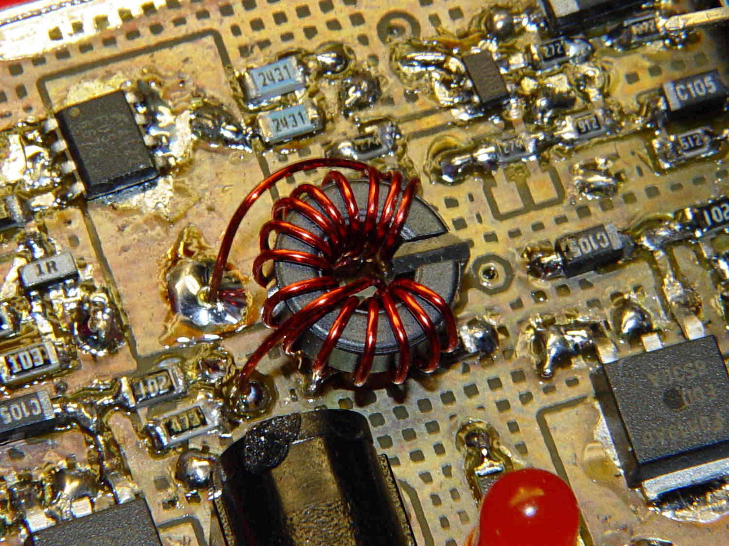
Although it’s not obvious, the two blue 2431 Ω resistors just above the toroid are a divider that scales the switched battery voltage (from the p-MOSFET on their left) by 50% and sends it to input A0 on the Arduino Pro Mini board:
The firmware can use that input to dim the LEDs when the voltage drops below some preset threshold and, eventually, turn them off completely.
Figuring the actual battery voltage is straightforward:
- get 10 bit ADC value with
analogRead() - multiply by actual VCC (measured at 4.96 V for this board)
- divide by actual voltage divider ratio (measured at 3.78/7.57)
Which, of course, reported the battery voltage was 4.116 V. Huh?
After spending far too much time poking the code with a sharp stick, I wired the divider to the (previously unused) A6 and A7 inputs and dumped the raw ADC counts for all three. The answer should be somewhere near 763, but the three values came out around 215, 667, and 750. Huh?
The A0 value is totally bogus, so I finally looked at the Arduino Pro Mini board:
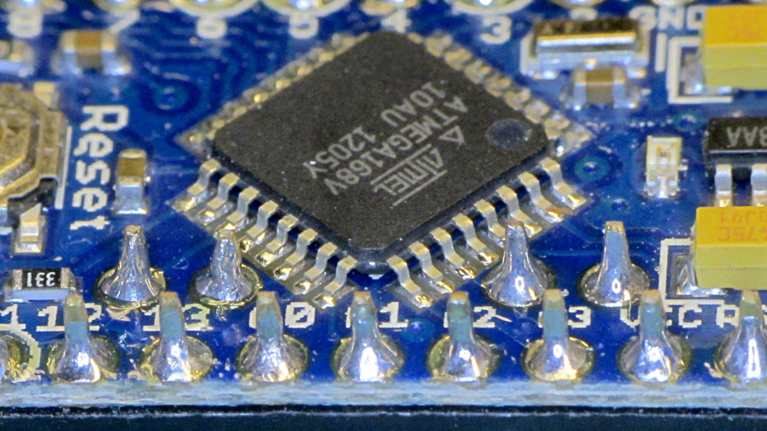
Hmmm. It turns out A0 is the second pin back on the left side:
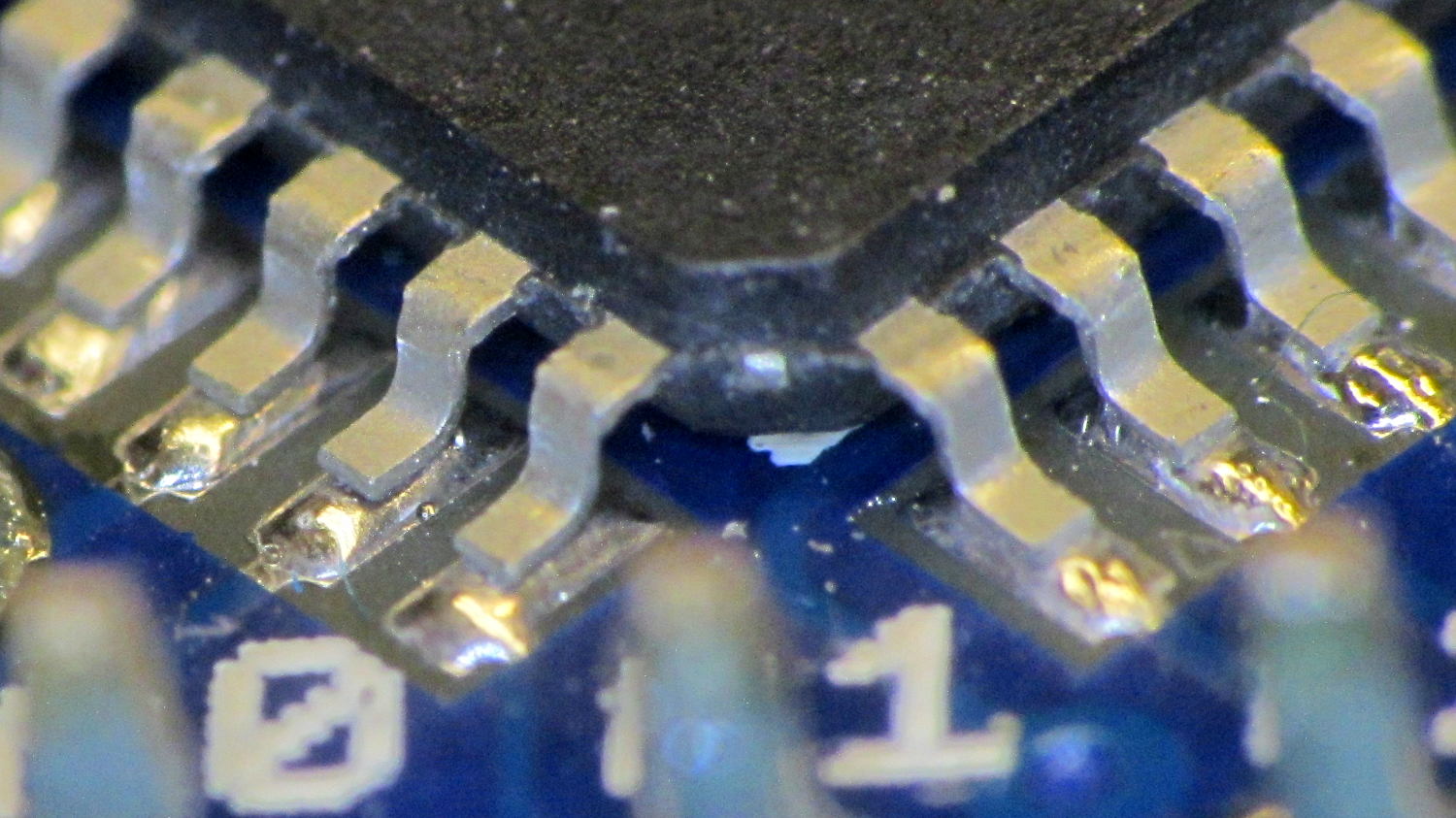
Double hmmm. An even closer look:
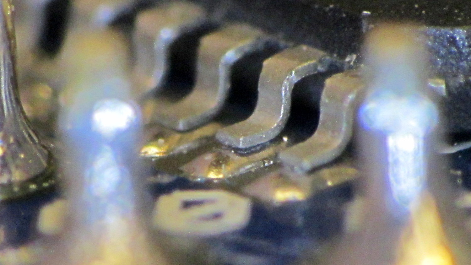
Well, that was obvious after I figured out where to look…
I slathered flux on all the pins, touched each one with a soldering iron, and it’s all good.
This is a knockoff Arduino Pro Mini board from eBay, of course, and the rest of the boards in that lot were OK. Their QC inspection almost certainly boils down to running the Blink sketch: if the LED blinks after the power goes on, ship it!
Blink doesn’t verify the analog inputs, which turn out to be wrapped around that corner of the package.

Comments
11 responses to “Arduino Pro Mini Knockoff: Solder FAIL”
Sigh. When I did test engineering (at the chip level, not the board), letting a FUBAR like that out the door would have meant either a long, uncomfortable talk with a manager or two, or on repeated offenses, a new job at Burger King. The first thing we did was check continuity to the pins. The cheap, it burns!
Given the amount of IC counterfeiting these days, one wonders about that little slab of black epoxy. Things might be just as iffy in there, too.
The brand-X LM108A in the mil-grade returned TO-5 can got Legal’s attention at National Semi in my youth. It wasn’t even the current design. OTOH, I’ve read of lead-filled gold coins dating back to the Romans.
Do you use enough of these to do a self-test sketch with a fixture? I know the headaches occur in the inverse proportion to the volume of a test project… (well, maybe a t*exp(-t) curve…)
It’s the first hard failure out of maybe a dozen knockoff boards of several different varieties, so I’d need a fixture to match three or four different Arduino footprints. The trick would be simulating enough failures to verify the fixture.
That notwithstanding, it’d make for an interesting Circuit Cellar column, wouldn’t it?
Along those lines, I knew a guy who decided to get out of military contracting when he had to write the spec for a failed diode that would be provided as a sample with a semiconductor tester…
Test philosophy is sort-of straightforward. 1) Make sure the pins are there. 2) Make sure they function, 3) check the parameters, DC, then AC. Incoming QA/selftest should concentrate on points 1 and limited portions of 2. It might be safe to assume the silicon in the epoxy worked before it was mounted in the board.
I’d do a ladder for the analog inputs and something to look at the digital IOs. Flip the bits, and test ins-vs-outs, unless it’s too much of a pain for bidirectional pins, in which case, pick the most useful direction. Such a project wouldn’t take too much more than all your spare lab time. [sigh]
Verily, hell hath no fury like that of an unjustified assumption: The Sparkfun Counterfeit Saga
A major geek-friendly chain in California built the bad reputation of selling “return-to-stock” stuff that occasionally held rocks. My brother-in-law was one of many burned. Not sure if they are still in business, but if you had to use them, you were careful with the “R2S” boxes.
BTW, if you really have to open an IC, get a small quantity (50 ml is plenty) of fuming nitric acid and an eye-dropper. Works fine at room temp. Getting such is left as an exercise for the
insanestudent.From what I read in that Sparkfun writeup, you add one drop of RFNA, let it work, rinse it off with acetone to avoid turning it back into ordinary nitric acid that will eat the metal & silicon, and iterate. Zowie!
You have the procedure right (Sparkfun did one with hot 65% Nitric) with the acetone as a rinse. Did it last in ’79. How soon we forget. [grin]
[…] Resoldering the switch solved the problem and, while the iron was hot, I touched all the microcontroller pins, too, just in case… […]