I’d originally planned to drive the new HBP with a boost converter from the 24 V supply brick, but that didn’t quite work out. The arrival of a 36 V brick from halfway around the planet solved that problem, but the RAMBo platform heater’s 15 A ATO fuse restricts it to 24 V and I don’t quite trust that MOSFET for high current applications, either.
Sooo, I went full-frontal Cupcake with a solid state relay screwed to a pair of existing holes (!!!) in the M2’s frame:

Note: that’s a DC-to-DC SSR, not the more common DC-to-AC SSR. Basically, it’s an up-armored optically isolated MOSFET, not a triac, and, yes, capitalizing acronyms and initalisms can be contentious.
Because the RAMBo’s MOSFET now drives the piddly current required to activate the SSR, I rewired the power to apply the M2’s 19.5 V brick to all three inputs by adding two red jumpers on the right side of the Phoenix plugs:
The M2’s hulking 12 V brick now resides in the Basement Warehouse’s Power Supply Annex.
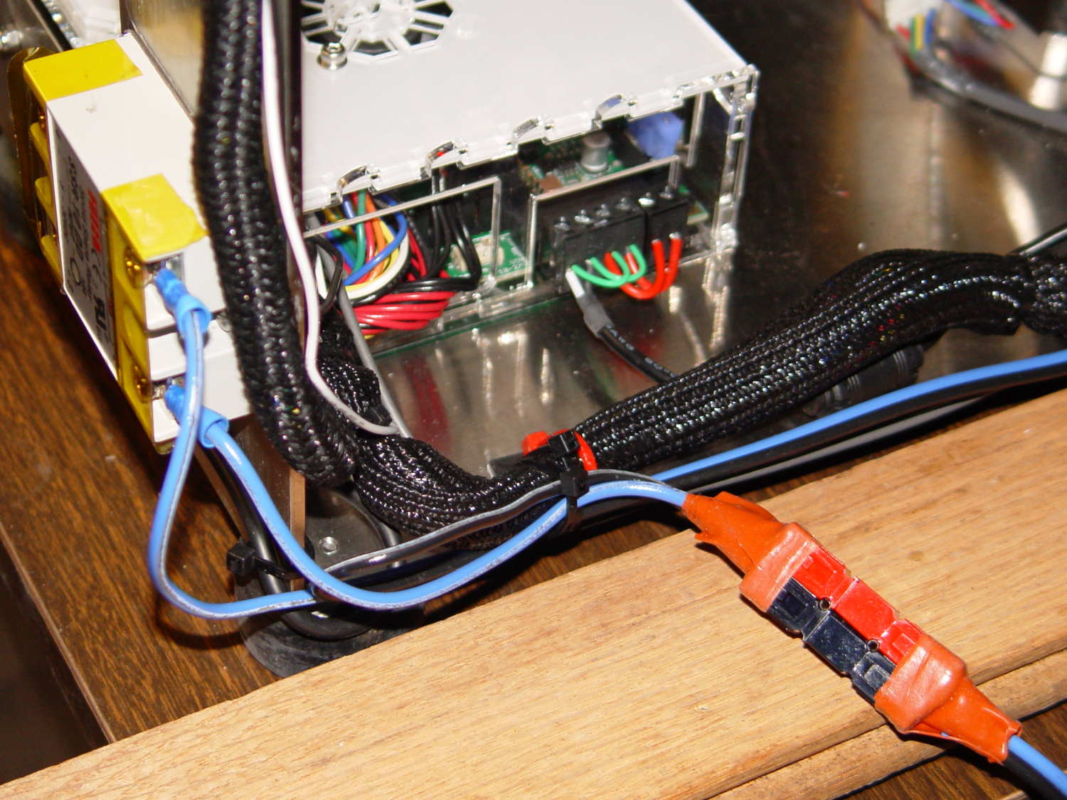
The HBP cable comes in from the right side and the 36 V supply arrives through the Powerpole connectors in the lower right. Tucking the ferrite slug on the 19.5 V supply behind the wire loom prevents the cable from pulling the Phoenix connectors out of the RAMBo board at an inopportune moment.
The original M2 HBP wiring got uncomfortably warm carrying the 10+ A for that platform. It would probably work OK at a lower current, but I’d already put Powerpole connectors on the new HBP. So I ran that cable outside the loom and abandoned the original pair inside.
The SSR switches the +36 V wire, leaving the HBP at 0 V when it’s not activated: supply hot → SSR → HBP → supply common. That makes no practical difference, but it feels like a Good Idea. Also, the Kapton tape across the SSR terminals should be barely adequate to prevent contact with random conductive clutter; I’m channeling the true spirit of DIY 3D printing…
I don’t have a connector matching the M2’s 100 kΩ platform thermistor, either, so I just ran the new cable down the outside of the loom and conjured up a two-pin socket for the header on the RAMBo board:

Plug it all together, tweak the startup G-Code to properly trip the Z-min switch at its new location, and it Just Works:

Those are thinwall open boxes that came out 5±0.03 mm tall across the array, so the platform is just about as level / aligned as necessary for my simple needs.
The Z-min switch will move to get rid of that stupid block epoxied to the platform, so I didn’t record the G-Code tweakage…
