The PCB under the improved flat-top glass platform has three soldered-in-place M3 screws that fit the M2’s Y stage support:

I applied a tiny rat-tail file to the holes until they became a free sliding fit for the screws.
The wave springs are mostly decoration, as the silicone rubber disks now take the compression load from the screws, and the platform is quite rigidly mounted.
The new platform eliminates the M2’s original aluminum support spider, the aluminum heater & heat spreader, and the corner supports & clips, all of which add up to about 780 g. I didn’t bother changing the Y axis acceleration to match, as all those numbers seem rubbery.
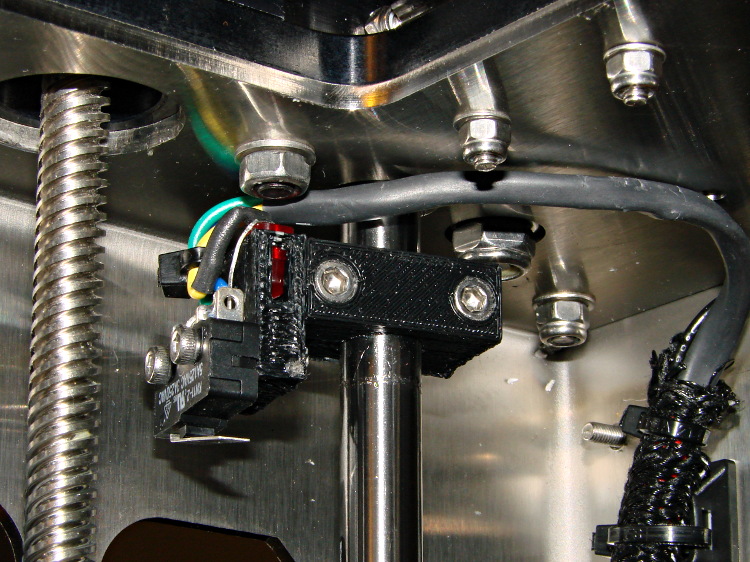
Minus the support spider, the platform rides much lower on the Z axis stage than the M2’s platform. Unfortunately, the Z-min switch clamped to the top of the rear Z-axis guide rod can’t get any higher, even after rearranging the cable and fiddling with the LED:
As a first-pass hack, I moved the switch to the rear of the X gantry and applied Gorilla Tape to hold it in place:

That required a small block to raise the platform enough to activate the switch before hitting the nozzle. I epoxied a snippet of brass rectangle tube to the left edge of the platform, directly under the switch lever:
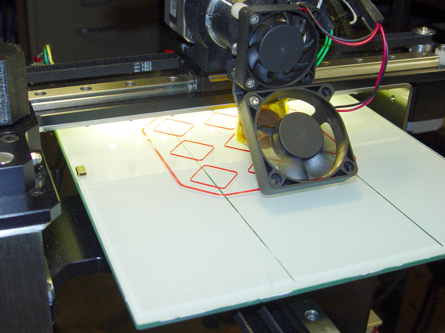
The awkward position activates the switch with the platform as far to the rear as possible, so that you can’t inadvertently drag the dangling switch lever across the block in the wrong direction.
I think it’s stupid, too, but it let me bring up the printer and make sure all the electronics kept working. The next step was to relocate the switch to a more rational place

Comments
6 responses to “Makergear M2 Improved Platform: Mechanical Adjustments”
[…] required no adjustments to the M2 at all; It Just Works. Admittedly, that’s with a custom platform and firm supports replacing the springs, plus better Z-axis homing, but the overall structure was […]
I’m finishing up the assembly of my brandy-new M2 printer this weekend and am concerned about the wiring to the HBP. One of the most glaring problems with my old Thing-O-Matic was the wiring to the HBP. After jillions of repetitive moves, the wires broke at the juncture with the connector. When I strengthened that area, the juncture between the HBP and the connector would break. I really couldn’t come up with a suitable solution and it get me a good excuse to upgrade. Now I see the M2 has a similar setup: a bundle of wires leading to three flimsy connections to the HBP. I haven’t seen any complaints in your column, but it makes me a little concerned. Am I being a nervous-Nelly?
Nope, not at all. Some folks on the Makergear M2 group have reported troubles with that connector, although I think more have had problems with the Phoenix-oid connectors on the RAMBo itself.
I added a stiffening spine to support those wires and move the flex away from the connectors; that will work better after you replace / supplant the platform springs with something like the silicone plugs I conjured up.
When I replaced the platform, I went for Anderson Powerpoles and a different wire routing, but that’s in the nature of fine tuning.
Wow, those posts are exactly what I was looking for. The channel under the HBP is such a simple solution that you wonder why it isn’t incorporated as part of the kit.
The M2 seems a mechanically solid design but still needs a few kinks wrung out. One giant leap for mankind above laser cut plywood though.
I think the spring supports must go, so that the wires can’t tilt the platform: tt’s bendy enough under high acceleration without having that long lever arm hanging out the back.
Plywood and acrylic worked fine for early, slow 3D printers, but that sun has set.
Glad to be of some use… [grin]
[…] the three leveling screws under the platform and iterating with more boxes eventually got the platform aligned to about ±0.07 mm across the […]