Dan sent me a Kysan 17HD-B8X300-A, a leadscrew-equipped stepper motor with much higher torque than the Makergear Z axis motor. According to the Kysan description, which is all we have to go on: 4.2 V @ 1.5 A means 2.8 Ω, at which current it produces 5.5 kg·cm = 540 mN·m of torque. I measure 3.2 Ω and 3.5 mH, not that that makes much difference.
I worked out some of the numbers in that post and, if they’re close, then the new motor has twice the torque of the OEM one. What’s more important is that the new motor will work correctly with a microstepping drive and won’t bake while doing so.
The new motor has more metal to it than the old one:
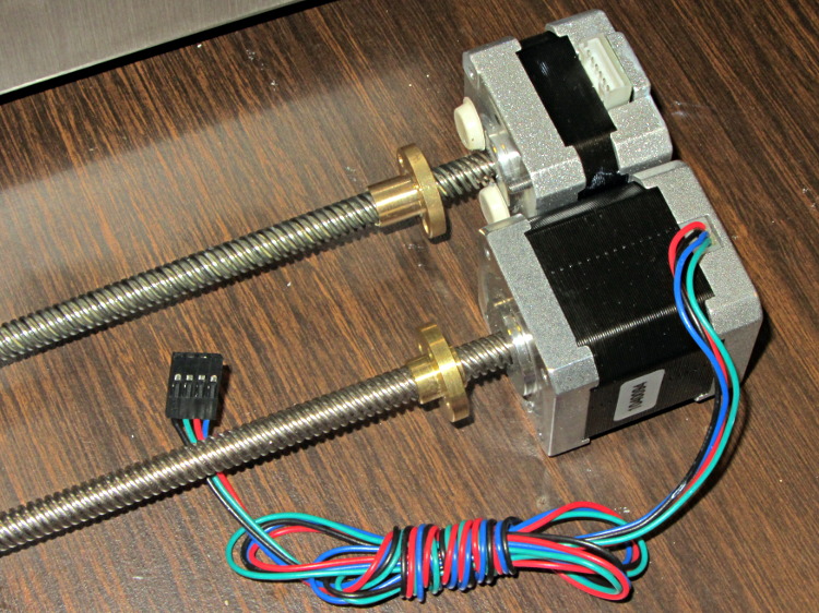
The leadscrew follower nut has unthreaded holes, but, mercifully, has the same OD, fits nicely into the Z stage, and those four holes line up perfectly.
I chopped off most of the wires and spliced a JST plug onto the end; of course, the motor ran backwards. Having foreseen that eventuality, I had not shrunk the tubing over the wires: swap a pair, shrink the tubing, and it’s done:
Some notes from the operation:
- Disconnect all the cables
- Remove HBP + glass plate
- Lay printer on +X side of the chassis
- Remove screws holding Z motor to chassis
- Remove nylock nuts and screws from leadscrew follower nut
- Remove Z axis home switch
- Run Z stage to top of rods
- The leadscrew bearing will probably have fallen out by now
- Loosen Z rod clamp nuts & bolts (top & bottom of rods)
- Push Z rods out using a nut driver, pull with a rag for traction
- Be ready to catch the Z stage when you remove the rods!
- Angle motor & leadscrew out of the chassis
- Angle new motor & leadscrew into the chassis
- Reinstall everything in reverse order
- Recalibrate everything…
The Z rod sliders have little balls inside, but they didn’t fall out during this adventure. I don’t know if that’s reliable information or not.
Now, to see what a better motor can do…

Comments
13 responses to “Makergear M2: Z Axis Stepper Motor Transplant”
Ah, you alluded to two of my common mistakes. Remember to put the heat stink on BEFORE I solder, and verify that the wiring is correct BEFORE shrinking it!
And keep your fingertips away from the tubing… [ouch]
I have the motor on order ($38.00 + $39.00 shipping from China) for the benefits you note. Another benefit I’m hoping for is improved accuracy and precision in reporting Z location.
I attempt to level the bed on my M2 by using a micro switch probe and LED attached to extruder. I get Z readings by sending M114, then adjust accordingly. I’m suspicious of the readings I’m now getting. They often describe a non-planar surface that the glass bed unlikely to be capable of.
In your opinion, am I likely to get improved accuracy and precision? Will the new motor accurately move, and support reporting, in 0.01mm increments?
Ouch!
If anybody’s up for a group buy, you could pass some along to other M2 owners for a slight profit… [grin]
There’s plenty of backlash in the Z axis drive, so retract by about 4 mm (half a leadscrew turn) before each downward move.
The plate on my M2 seems to be slightly bowed along Y, with the central Y=0 line slightly higher than it should be. I’m tinkering up a better mounting system that may solve some of that, but …
Numbers! We need Numbers! Lots and lots of Numbers!
I looked at printing that dial indicator holder, but the OpenSCAD model has misfits between the various shapes. I plan to build a somewhat different holder as part of this process.
Because they both use the same 1/16 microstep drive, the two motors will (uh, should) move the stage to the same place along the Z axis and they’ll have the same mechanical backlash. However, the new motor will be much less likely to lose steps due to inadequate torque and, given more torque, it can drive the stage faster with higher acceleration.
“There’s plenty of backlash in the Z axis drive, so retract by about 4 mm (half a leadscrew turn) before each downward move.”
AHA. I only retract 1mm. I’ll make some runs at >= 4mm and report the NUMBERS.
Do you print on the glass or the HBP? My HBP is bowed by ~ 0.7mm at midpoint of Y axis.
I’m not a fan of using the nozzle & paper as a probe. And dragging a metal dial indicator tip across the glass surface makes my teeth itch. The microswitch & LED probe did a good job on my Prusa. I used Z steps of 0.01mm. I hope I wasn’t deceiving myself in trusting the accuracy of the M114-reported Z position when light came on. I removed the metal leaf in order to activate switch with the plastic nub.
I’ll send photo with NUMBERS.
Atop the glass, with some hairspray to nail down the PLA.
In principle, the glass should remain flat no matter what’s going on underneath, with the air gap taking up the slack. I think working at tolerances required for layers under 0.2 mm thick requires more attention to detail than just binder clips, but … the M2 is far better than the Thing-O-Matic ever could be, so I’m not complaining.
You just need a longer retraction move… [grin]
Actually, glass is harder than the steel end of those indicators, so there’s not much harm to come from dragging the ball. But the right way to do it is to get some Z clearance before starting the XY motion!
That’s overly optimistic, because the M2’s Z axis has 400 step/mm = 0.0025 mm/step. That means a 0.01 mm move requires only four steps, which probably isn’t enough to overcome the usual stiction and bendiness. You also run into the problem that the microstep positions aren’t particularly accurate.
Tool length probing on the Sherline involves feedback from the switch to the program, so that the probe moves down until it trips. The continuous motion ensures that all the backlash / stiction / bendiness affects all the measurements the same way.
You can’t do that manually, unless you do a complete retraction between each motion and feed it 0.01 mm more on each move. When the LED finally comes on, you know the exact distance to the trip position.
[…] the M2′s heated build platform connection flex as the Y stage travels back and forth. After replacing the Z axis motor, I added a strut to the Y axis stage to stabilize the HBP […]
My Kysan motor arrived today … while I was away for a few minutes. Grabbed the FedX sticker from the front door, hopped in the car & thought about the route driver would take. I found him & got the motor.
I wanted to run one last test on the original motor. Pronterface wouldn’t connect. I pulled the USB cable out, planning on re-inserting it. The female connection that WAS attached to RAMBo is now attached to USB cable. No printing for awhile.
Now to the motor swap: “•Angle motor & leadscrew out of the chassis” Adding two words is recommended: “the back”
The Kysan motor has screws in the bottom, holding the motor together. Neither these, nor the MakerGear screws are long enough. Looks like I need ~ 40mm M3 screws. Fortunately, there’s a REAL hardware store nearby. Closed now; open tomorrow.
I must have a different version of the motor than you.
The swap gave me opportunity to thoroughly remove all original lube, as well as the STP I tried. Engine oil is now my only lube. Lot’s of good reasons, including: ABS-friendly, high film strength, corrosion resistance, very slippery …
I’ll use the down time to finish the slide show I’m making for upcoming HS class reunion.
Thanks for the exercise, Ed. I’ll post my progress.
Oh, does your photo accurately depict wire color code connections?
No points for style: as long as you don’t bend the new leadscrew, it’s all good.
I wound up cutting a pair of 60 mm screws down to just over 50 mm. Alas, 40 mm doesn’t quite reach the motor endcap threads.
Rather than take all four screws out, I left two in place to hold the motor together. Maybe it doesn’t matter, but I’d rather not find that out the hard way. The screws had flattish heads that didn’t project outside the endcap recesses, so the motor sits flat on the chassis.
Yup, the picture shows the proper sequence… after I resoldered the two offending wires and shrank the tubing.
Of course, that assume the colors on your motor match mine, which is definitely a Bad Assumption: I recommend not shrinking the tubing until after First Motion!
You’ll like it, for sure…
RE Wires:
My motor has Red, Blue, Green, Black.
Your photo, reading left > right looks like:
Red > Red
Bl > Gr
Gr > Y
Bk > Bl
Correct?
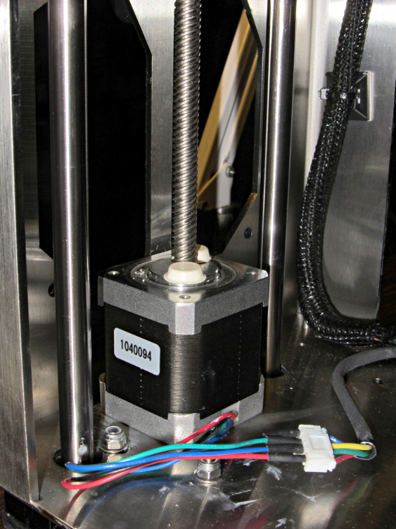
My motor has the same numbered stick-on as yours = 1040094
I needed 50mm flat-head screws. I like your idea of replacing only two.
My lead screw follower has tapped holes. I used the MG for its greater length.
I now have 180 mm vertical travel, with ~ 5mm of bumpers on motor.
Thanks for sharing your knowledge.
Here’s the straight dope on the connectors:

You can use ordinary socket head cap screws through the chassis; there’s enough clearance for the heads down there.
A bit less than the stock M2, but the tradeoff with torque works for me!
“You can use ordinary socket head cap screws through the chassis; there’s enough clearance for the heads down there.”
Wanted to; HW store doesn’t stock.
With that photo, as is often said: “What could possibly go wrong?” Thank you.
I’m afraid I’ve given up on the local stores for parts: I can’t justify driving(*) around town to find things and I’ve learned that there’s no point in trying to describe an M3x0.5 socket head cap screw that’s 50 mm long over the phone to someone unfamiliar with such things.
I’m sure you’ll let us know… [grin]
Glad to be of assistance!
(*) I can justify a bike trip, but not in 95 F weather…