Several users have observed that the stepper motor driving the M2’s Z axis leadscrew gets very hot. I measured about 140 °F = 60 °C on the as-built motor, so I loosened the screws and raised the motor slightly:
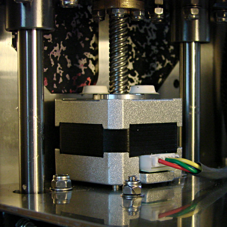
I eased some heatsink compound underneath by putting dabs on a slip of paper and painting it on the bottom of the motor case, lowered the Z stage to the bottom of its travel, and tightened the mounting screws:
That reduced the temperature to about 120 °F = 50 °C, which still seemed excessive for a short-stack motor mounted on a fairly large chunk of stainless steel. The motor also sounded quite rough during homing and long manual moves, sooo … something was wrong. I bet you know where this is going, right?
Let’s start with the firmware side and determine what current the motor should be seeing.
The M2 uses a slightly modified version of the Marlin firmware running on a RAMBo 1.1b board. The basic RAMBo doc gives these equations relating the peak winding current Imax to the constant W that defines it in the firmware:
Vref = 0.8 * Imax
W = 255 * (Vref / 1.66)
Mashing those together produces this:
W = 255 * (0.8 * Imax) / 1.66
The default Z axis stepper current constant W (called Z_CURRENT in the Marlin source) is 135. The board in my M2 has R30 = 3.3 kΩ, which sets the maximum possible current to 2 A. Working the equation backwards, a Z_CURRENT = 135 will produce a peak winding current of 1.1 A.
However, a nearby comment in the source code suggests this is should be about 0.75 A. The original RAMBo board had a maximum possible current of 1.5 A, but running those numbers doesn’t agree. Another comment suggests 185 corresponds to about 1 A, which isn’t right, either. There’s nothing new about stale comments not corresponding to the actual hardware; I’ve done that myself.
With 1.1 A in hand, let’s unplug the cable and measure the winding resistance.
Not much to my surprise, the motor has 28 Ω windings. The M2 uses a 19 V supply for the steppers, so the maximum motor current works out to 19 V/28 Ω = 680 mA, but it must be less than that to allow the microstepping controller to manage the current.
It seems that Makergear is connecting a high-resistance stepper intended for a simple H-bridge drive to a high-performance microstepping controller. For some background on why that combination doesn’t work, see my analysis of the original MBI Thing-O-Matic steppers.
I thought we all agreed we weren’t going to do that any more. Maybe nobody sells a low-resistance motor-with-integral-leadscrew?
Anyhow.
The only thing to do in the short term is to reduce the peak current to a rational value around 600 mA:
74 = 255 * (0.8 * 0.6) / 166
I set it to a nice, round 75 and reloaded the firmware, which immediately made the motor hum, rather than growl, on long moves. The case temperature didn’t drop by very much, because the poor motor still dissipates about 11 W, not much less than the original 13 W. There’s only so much heat you can pull out of the case and these little motors are actually rated for maybe 5 W, tops.
The motor’s overall performance didn’t change, which is good, because it didn’t have much performance to begin with. The X and Y motors can accelerate at 9000 mm/s2, but the Z motor limit is 30 mm/s2; it doesn’t really accelerate, it sort of gains momentum in a stately manner.
Next: let’s see if it really matters.

Comments
12 responses to “Makergear M2: Z-axis Stepper Motor”
“Maybe nobody sells a low-resistance motor-with-integral-leadscrew?”
No, they sell them, not many people use them http://store.kysanelectronics.com/servlet/-strse-71079/17HD-dsh-B8X300-dsh-A/Detail
One thought I did have on why not, that linked motor has huge torque and likely, should it hit a hard limit, something might break before it skips steps. Also, quite a bit different if one had (notice the past tense) a finger in the axis?
For that price, building a little coupler between a stock motor and a stock leadscrew looks downright attractive…
I’m pondering whether I can drill an axial hole in the end of the leadscrew for the motor shaft, tap a crosswise hole for a setscrew, slobber Loctite inside, and jam it all together, while maintaining enough concentricity to not mess up the Z axis alignment.
Likely not, although real CNC machinery has genuine hard limit switches to prevent exactly that outcome. Adding another switch on the Z axis might make sense, because the motor I have on hand produces about that much torque: it’d definitely put some hurt on the setscrew and shaft.
I’m pondering whether
For what it’s worth, why not a flex coupling? I have something in my surplus stash that tied a stepper to a leadscrew. This is a helical coupler and is reasonably small, about 3/4″ in diameter and an inch long. Stock Drive Products sells a range of these–no idea of prices. There are also bellows couplers that are similar in dimensions.
My first thought was a pulley and timing belt, but I think that’s the road to madness..
good precision, though.
Last line was a leftover… Oops.
Looks like 30 bucks for a mix-n-match spider coupler, which isn’t terrible. I don’t know how well the couplers would grip the leadscrew, but a dose of Loctite ought to improve its griptivity.
The gotcha is that the whole affair is 30 mm long. I’d like to lose less Z axis travel than that, which is tough given that the replacement motor is 20 mm taller than the OEM version.
More musing is in order…
FWIW while the idea of digipots is interesting, in some circles, we are concerned what happens at boot. We think in another system that is prone to letting the magic smoke out, the bootloader and/or board layout (EMI/RFI) is letting those digipots toggle to invalid ranges. Also, the failure seems linked to doing just such an action on a higher inductance motor such as your Z. This could cause the current limiting function to get into a pickle and inductive kicks then blow out the diodes protecting the H-bridge resulting in catastrophic failure.
Just something else to look at. Who knows what random bits flow down the I2C bus at boot?
An I2C transfer requires so much handshaking and bit-twiddling that a device is unlikely to receive a valid-but-erroneous command by accident. Of course, that’s assuming the processor wakes up from a reset / shuts down on a brownout in the correct manner, which seems to not be a foregone conclusion with some designs.
(SPI is a different matter. A pulse on the parallel latch line will transfer whatever startup junk appears in the shift register into the device. Most devices have a known-good default state, but if the serial clock starts up before the parallel latch blips, all bets are off.
The M2 uses PWM to step the 19 V supply down to 12 V for the fans, which I dislike for exactly the reason you describe. Fans are cheap and easy to replace (and actually fairly tolerant of overvolting), but it’s the principle of the thing.
I’m not so sure about that, as the diodes never conduct more current than the driver transistors and (assuming they’re properly rated) should work just fine. A higher winding inductance means the current increases more slowly, but doesn’t affect the maximum value. The stepper driver should start current regulation regardless of what the microcontroller is (or isn’t) doing, so the worst case is that the motor sees more current than it should, but that occurs only until the controller finishes booting and shuts the drivers down (assuming that’s what it does normally).
You’d need to puzzle through the schematic and code to figure that out, assuming those are readily available. [grin]
[…] « Makergear M2: Z-axis Stepper Motor […]
[…] Increasing the homing speed moved the vibration away from the resonance, but the real cure was to reduce the motor current, which eliminated the four dead spots per full […]
[…] from the Z axis motor, the actual maximum speed seems to be around 30 mm/s = 1800 mm/min. After I replace the motor, I’ll measure the actual performance and see what’s […]
[…] sent me a Kysan 17HD-B8X300-A, a leadscrew-equipped stepper motor with much higher torque than the Makergear Z axis motor. According to the Kysan description, which is all we have to go on: 4.2 V @ 1.5 A means 2.8 Ω, at […]
[…] NEMA 17 motors dissipate about 5 W (13 W if you’re abusing them) […]