Building these things seems to be the simplest and best way to figure out whether you have all the pieces flying in formation:
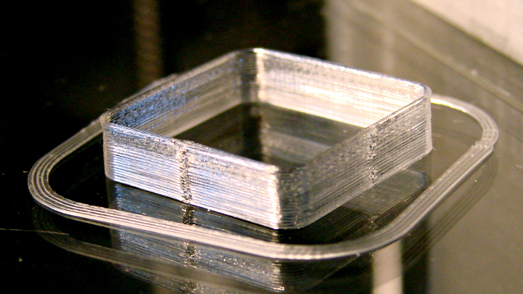
I took that picture after cracking them off the glass plate, then putting them back: the box really does line up with the skirt while printing. There’s another object visible in the background; that little box really was the first completely successful object.
It’s adapted from Coasterman’s classic calibration set, redone in OpenSCAD so it’s easy to modify. A pair of Minkowski sums produce two shapes that ensure the wall remains exactly one thread wide all the way around the perimeter.
[Update: The revised version works better.]
When your printer can print one of these, then you can move on to more complex objects, secure in the knowledge that you’ve established:
- Proper bed leveling and height setting: measure the skirt thickness
- Both the layer thickness and width match your settings
- Extrusion temperature: not too hot, not too cold
- Printing speed / acceleration for all layers
- First layer adhesion to platform
- Minimum layer time to prevent melting / slumping
- Filament diameter
- Extrusion “packing density” multiplier: the fundamental fudge factor
- Accurate steps/mm for all axes to get exact XYZ dimensions
- Mechanical stability and rigidity
Basically, this object leaves no place for errors to hide. It doesn’t check infill, the various perimeter speeds, solid layers, and suchlike, but all the fundamentals must be correct or you’ll see painfully obvious flaws.
For example, there’s a bit of a zipper at the layer changes. It’s better than the Thing-O-Matic ever was, but it improved as I twiddled the Retraction settings on later objects.
No, the first few didn’t work quite that well:

For what it’s worth, the last problem turned out to be a loose setscrew in the X axis motor pulley that produced a layer shift that closely resembled a stepper motor losing steps. All of the setscrews now sport a dab of low-strength Loctite, so that problem shouldn’t happen again.
Yes, I did the happy dance…
The slic3r header:
; generated by Slic3r 0.9.8 on 2013-03-26 at 11:01:10

; layer_height = 0.25
; perimeters = 1
; top_solid_layers = 3
; bottom_solid_layers = 3
; fill_density = 0.20
; perimeter_speed = 100
; infill_speed = 150
; travel_speed = 500
; scale = 1
; nozzle_diameter = 0.35
; filament_diameter = 1.70
; extrusion_multiplier = 0.9
; perimeters extrusion width = 0.40mm
; infill extrusion width = 0.40mm
; first layer extrusion width = 0.39mm
The solid model has no surprises:

The OpenSCAD source code:
// Thin wall open box calibration piece
// Adapted from Coasterman's Calibration set
// Ed Nisley - KE4ZNU - Dec 2011
// Adjust for Slic3r/M2 - March 2013

//-------
//- Extrusion parameters must match reality!
//  None of the fill parameters matter

ThreadThick = 0.25;
ThreadWidth = 0.40;

Protrusion = 0.1;           // make holes end cleanly

function IntegerMultiple(Size,Unit) = Unit * ceil(Size / Unit);

//-------
// Dimensions

Height = IntegerMultiple(5.0,ThreadThick);

WallThick = ThreadWidth;

CornerRadius = 2.0;
CornerSides = 4*8;

SideLen = 20.0 - 2*CornerRadius;

Rotation = 45;

//-------

module ShowPegGrid(Space = 10.0,Size = 1.0) {

Range = floor(50 / Space);

for (x=[-Range:Range])
for (y=[-Range:Range])
translate([x*Space,y*Space,Size/2])
%cube(Size,center=true);
}

//-------

ShowPegGrid();

rotate(Rotation)
translate([0,0,Height/2])
intersection() {
difference() {
minkowski() {
cube([SideLen,SideLen,Height],center=true);
cylinder(r=CornerRadius,h=Protrusion,$fn=CornerSides);
}
minkowski() {
cube([(SideLen - 2*WallThick),(SideLen - 2*WallThick),2*Height],center=true);
cylinder(r=CornerRadius,h=Protrusion,$fn=CornerSides);
}
}
cube([2*SideLen,2*SideLen,Height],center=true);
}
[Update: You should use the code from the revised version.]

Comments
24 responses to “Makergear M2: Fundamental Test Object”
For positional accuracy, had you ever considered attaching a touch-probe and measuring something like a 1-2-3 block or some other object? This may not be such a big issue for a cartesian system like M2 has (if you assume everything is straight and perpendicular) but I’ll (hopefully) be receiving a Deltamaker later this year and I am stymied considering how they will calibrate that thing. Hoping everything is straight and relying on the math being correct seems like a really bad idea. So I had the thought of putting calibration objects in the print volume in known positions and orientations and measuring them with a touch probe. Assuming the build plate was flat, you wouldn’t even have to spend time making sure the build plate was leveled (so long as you aren’t offended that “up” might lean a tiny bit.)
These delta robots are pretty cool in that they have no possibility of binding and are always precisely constrained, but the disadvantage is that they really have little to reference (except for the Z axis) for basic cartesian positioning. You can spend a lot of time improving the accuracy of a cartesian robot through little physical tweaks. I don’t see that as possible with a delta so calibration is a must.
I have not done the math, yet, but if the positioning precision of the slides is on the order of .0005in, I’ll just take a guess and say that any x,y,z coordinate is going to have a positional inaccuracy of at least .001in assuming everything is perfectly stiff and the 1/16 micro-stepping is linear (I feel really certain it isn’t.) Moreover that is all the time. So if you print a plane, it will have an interesting pattern of waviness associated with the reverse kinematics converting arm positions to a cartesian system. Oh boy! Math!
I suspect, though, that .001in isn’t going to amount to much in this type of system, but still, I may want to attach a Dremel via flex cable to it and try milling little things like PCBs.
On another highly related topic, do you know a good place to read about controlling coordinated trapezoidal moves? I’d like to at least understand how it is done and maybe try my hand at writing some code to do it.
Delta robots are sort of like recumbent trikes: they’re insanely neat and I love the idea, but I also can’t see riding one on the roads around here…
That’s definitely in the cards, but it’ll wait until I have the LinuxCNC controller running.
I can then probe the entire glass plate, generate a height map file, feed it into the kinematics module, and automagically correct for platform tilt and warp on the fly. That should go a long way toward pasting the first layer to the platform without heroic hairspray efforts.
Well, that’s 0.025 mm = 25% of the nominal 100 micron Z resolution… so I think it’s significant.
I’d like to see measurements of the mechanical alignment / backlash / repeatability in a delta printer, because I think that’s what will affect the overall results. At the platform edges, the Z axis positioning accuracy (slides along the columns) and XY alignment (beam alignment / warp / twist) hit their worst cases at the same time, so that’s where to start looking.
Delta pick-and-place robots go scary-fast, but the positioning accuracy seems just good enough to handle candy bars and suchlike; I doubt they’re quoting XYZ accuracy / repeatability in microns. The SMD pick-and-placers, where microns matter, seem to be Cartesian for well and good reason.
Haven’t a clue, but that’s what both LinuxCNC and Marlin / Sailfish do, so you could Use the Source… [grin]
sort of like recumbent trikes: they’re insanely neat and I love the idea, but I also can’t see riding one
Alas, I agree. About 20 years ago I purchased one, but it was a prototype of a model that got much better later on. Like “don’t buy a car in the first year of model life”, a good deal on a prototype is dubious. Too many issues that were welded into the frame to be tweaked. If they had been adjustable, no problem, but nope.
Beyond that, the concept is OK for some kinds of riding, preferably dead flat and quiet roads. Usually had neither, but did OK on a ’86 Rockhopper fitted out for roadway use. The trike was either painful or scary. The pain would have been fixed by production tweaks, the inherent width bakes the fear factor in.
Should have bought a ‘bent bike. My back and the ‘hopper were old enemies by then (after a lot of riding–14K miles in one year), so once the trike fizzled, I dropped riding.
It’s never too late…
It’s never too late…
Not so sure. I still have my own knees, and they usually don’t kill me, but I’ll stay with the 13 acre exercise plan. My brother-in-law thinks we would have plenty of time for relaxation after retirement. Yeah, right.
I have some pros taking down 10 Ponderosa pines tomorrow (when they have to fall the right direction, I know to pay somebody else) that will need to be turned into stove lengths to dry this summer. Wood, it heats you up a few times before you get to burn it.
Microstepping is absolutely not linear and even beyond just this issue, deltas specifically are even more susceptible to this non-linearity than Cartesian printers because each of their axis can go up or down whereas in Cartesians X and Y are plumb. When the axis goes up against the gravity, the load increases and the non-linearity grows (unpredictably!) as well.
For this very reason I am looking for a stepper driver that would take single step commands from the CNC software but add 16 microsteps in between each step command on its own. The idea is to provide the reliability of single step positioning while softening the vibrations of the mech parts wear by still using microstepping. Anyone knows a driver like that? It’s something that would be trivial to do by adding a small MCU to a more traditional chopper driver but I’m wondering if someone has already included the feature in their driver just to keep the parts count lower.
The gotcha: you don’t know how long it will be until the next full step pulse arrives, so your driver cannot meter out microsteps at the proper rate. If you wait until that next step occurs, then you can move at the proper average rate for the previous step, but you can’t produce proper coordinated motion with the other axes. Also, you can’t do velocity / acceleration / jerk blending (basically, matching the derivatives) around each major step, because each motor isn’t privy to the Big Picture of Motion Planning.
The motor can’t tell where the microstep comes from, because the winding current isn’t a function of anything other than the desired rotor position. If you’re going to do microstepping, it must be under control of the motion planner, which meters out each microstep for each motor at the proper instant.
It’s a wonder steppers work as well as they do!
I’d say this is probably easily counteracted by limiting the frequency of single step commands to no more than 16 times the frequency of microsteps. If you look at it from the path planning perspective: it is still better than to race straight to the position of the full step. I do some laser cutting and my accuracy measurements come from analyzing the results and the end result of not having microsteps is the laser cut looks like a sewing machine stitch – there’s a hole where the step ends but there’s no cut where the stepper raced to the next stop, then another hole at the next stop. But OTOH, if I rely on microsteps for actual positioning instead, I’m seeing the error accumulating randomly (on both axis) because the direction changes often and continues for uneven number of steps the mis-steps cannot recover.
Bingo! This is a classic case of not bringing enough stepper motor to the problem.
When the motor does not produce enough torque to handle the dynamic loads and misses steps, you cannot improve the situation by applying increasing cleverness. You simply need a motor with more torque for a given current or a higher winding current limit if it’s not maxed out (under whatever conditions it’s operating in).
It’s basically that simple. A correctly designed stepper system does not lose steps under normal operating conditions. Conversely, if a motor loses steps, it’s not properly designed for the task at hand.
Admittedly, the whole system analysis thing requires more information than is available for most of the DIY machinery, but that doesn’t mean it shouldn’t happen… just that it doesn’t.
Well, I hear what you are saying and the thing could really use larger steppers BUT since it never misses full steps, it’s hard to call it underpowered because truth is, I would not be able to trust microstep positioning anyhow. For example, unless the stepper size is completely overblown, the motive force of some of the microsteps in 1/16 step is so small that there’s no actual movement going on between microsteps. Your CNC may be duped into thinking that the tool did really move three microsteps forward, then one microstep back (totaling two MS forward) whereas in reality the one MS back was so minute that the tool did not actually move and is physically still located at 3 MS forward. Then combine the uncertainty of 2 (cutter) or 3 (milling, 3D printing) axis and you’ve got a complete chaos after the tool had to change direction enough times.
Anyway, I’m at the point where I may be fine with the accuracy of the full step control but would like to still use MS to smooth the movement a bit and decrease the vibration/noise/wear on the machine.
By the way, if you are using 0.5mm or 0.35mm nozzle, all of this MS talk may be a moot point – it won’t make much of a difference because the size of the PLA bead will conceal the missing microsteps. When I start focusing my laser down to 25-50 micron range – that’s when straight cuts at acute angles to axis suddenly start looking like saw teeth. And when I see irregular distances between the teeth – that’s how I know that there were microsteps that did not lead to an actual physical movement.
Sorry for the long-winded comment, gotta wrap this up!
Cheers!
Forgive me for pointing this out, but you’re complaining about a motor that doesn’t have enough torque, while simultaneously claiming that a more capable motor would be too large. I contend that the right way to approach this is to figure out what size motor will have enough torque to handle the required load, then design that into the system.
Admittedly, I tend to be a bottom feeder and measure / use eBay crap rather than buy top-dollar retail equipment from a reputable supplier. Fixed income and all that, don’cha know. [grin]
Another way to look at it would be that you don’t have enough geardown between the motors and the motion: the full steps move the carriage too far. If you geared them down, say, 5:1, you’d get five times the torque, 1/5 the speed, and probably good-enough resolution. That may well be the problem with some extruders, where a direct-drive motor pushes the filament too far with each step…
That’s not strictly true. While the microstep accuracy isn’t precisely 1/N, the individual stopping points are pretty close, the error is non-cumulative (albeit periodic), and, in any event, when the rotor is turning, the average position / trajectory will be fine. After all, those full steps tend to nudge it into line and they’re not all that far apart.
The mechanical backlash exceeds the microstep resolution by maybe an order of magnitude and the controller should account for that; the fact that 3D printer motion control doesn’t is a historic accident. On my Sherline, the backlash is on the order of 0.08 mm and the stepping resolution is 0.002 mm; obviously, the microstepping resolution doesn’t affect the position for quite a while after a direction reversal. You may be seeing that same effect with your laser cutter; backlash can produce baffling errors until you measure it against the results.
Also, the total motor torque is the Pythagorean sum of the two winding currents, so the resultant actually has a more-or-less constant value. The restoring torque isn’t symmetrical about the nominal microstep position, but neither 3D printers nor laser cutter must resist cutting forces. If the motor can handle the maximum acceleration torque, then you’re good to go.
I did some admittedly crude measurements that seem to confirm that.
Aye, it’s the blob! I love all the talk about “25 micron resolution” when they never mention the resolution is maybe 800 microns in the XY plane…
The gotcha with Marlin is that (AFAICT) all axes must have the same microstepping settings. That means the XY axes run at 88.88 step/mm and Z runs at 400 step/mm. You could pick different numbers with a different controller.
[…] « Makergear M2: Fundamental Test Object […]
Reblogged this on Polytech's WordPress Place and commented:
Test 3D prints. Not quite art pieces but print a bucket full of them, dump them on a table and take great care making a photograph of them, and they appear as something more than just test 3D models.
By the way, I initially though the slanted position of the internal cube against the outer frame on the first picture was intentional. You don’t want that in a production 3D model but for calibration this approach works: as soon as you add long straight lines at acute angles, inaccuracies of stepper movement, non-plumb axis and other issues start popping up.
Despite having read about it, I was pleasantly surprised by PLA’s glittery quality: the thin wall boxes seem prismatic and larger objects cry out for internal illumination!
And you’re exactly right about the angle, because I wanted to see whether the glitch followed the model or the machinery. Of course, it followed me… [sigh]
Hi Ed, you’re right I also think PLA-printed models are looking very nice when backlit (or lit from underside) . Kind of blows my mind every time – from (yellow) corn to an almost transparent plastic – wonders of modern chemistry.
As far as test prints and prismatic shapes of the PLA layers – bingo again! As soon as you start seeing a rainbow in a ray of Sun light coming through your test print, you know there’s no more accuracy you can squeeze out of this puppy :) at 450-500nm per step there’s not much more you can get out of the steppers (and not much more would be needed, really).
So, are you seeing rainbows yet?
Cheers!
Nick
Those thin box walls definitely have a nice rainbow shimmer in full sunlight: I’ll call it a win!
Ed, could not respond to your last comment directly – the reply button is gone. So, I’ll try the restart a thread.
You do make excellent points but the reality is that the hardware is a given (and yes, not the top of the line) so more power of the motor can only be achieved by cranking up the current and I would want to find some kind of a balance between the “clever” driving which you eluded to earlier and the least current I can afford in the hopes that the hardware lives longer.
But back to the fascinating MS accuracy topic – I am trying to eliminate the HW backlash from the eqby analyzing cuts made in one direction of each axis
There’s a four-deep limit on comments, because the WordPress template shrinks the column width into absurdity.
In that case, you must adjust the machine’s velocity and acceleration to match the motor’s capability, not your desires. [grin]
The motor must produce enough torque to overcome friction from the leadscrew and slides supporting the stage, plus any mechanical binding due to overconstrained supports (like the Thing-O-Matic’s X axis bushings). Whatever torque might be left over is all you have available to accelerate the stage; if there’s no torque left over, then you don’t get any acceleration.
If the acceleration and velocity fall below what you want, then the only way out is to get more torque: reduce friction / binding, increase the winding current (keeping the operating tempeature in mind), or install different / larger motors. It’s that simple.
Blaming a stepper motor for missing steps when it’s operating beyond its spec isn’t productive, even though everybody does it…
Premature posting, sorry :(
Anyway, I will try to do a test with mounting a small mirror to the screw ( this particular case I keep referring to is a screw, BTW – a belt would be a different story) , bounce a laser beam off that mirror and feed the stepper individual microsteps to see if the dot moves on a far enough wall. I am absolutely certain that this (and perhaps every other machine in existence) could use more powerful steppers, but I have a hunch ( and at this point it’s just a hunch) that even if I free the coupling from the screw, the motor itself might still not show exactly linear angular response to microsteps. It will take me awhile to figure out the mirror positioning, so I may not be able to add much here but will be sure to come back to tell result.
All that said, what my cutter really needs is geared servos with good enough encoders for the continuous rotation of a brush/brushless DC motor is much better for uniform cutting. I would venture a guess that continuous (as in having no actual individual steps) movement of X and Y axis can benefit 3D printing quality, too.
Cheers!
Nick
That’s a great idea: an optical amplifier!
I should steal that idea and try it out here: I’ll be bringing up that LinuxCNC box with some motor driver bricks. I have some stray motors in the heap, so a little mirror mount on the shaft should be a simple matter of 3D printing. [whee!]
Ah, but notice what you’re proposing: gearing the servos has the same result as gearing a stepper. The positioning accuracy of a servo depends on the resolution of the feedback encoder, so gearing the rotation serves to increase the encoder’s resolution. However, if you put the encoder on the output shaft, then the position resolution will be no better than the encoder resolution. It’s no different with steppers, so if you’re willing to gear down a servo drive, you must also gear down the stepper to make a fair comparison.
Granted that an encoder will (probably) have better accuracy than a microstepped motor, but if you’re gearing down the motor and driving a leadscrew, then I suspect the resolution of either will be far below the mechanical backlash at the stage. You may be able to measure a difference, but it might not actually mean anything.
It’ll be interesting to find out, though!
[…] a few quick measurements while getting the printer running, I settled on extrusion multiplier = 0.9, so the actual step/mm […]
[…] I set up the extrusion multiplier to produce parts with accurate dimensions, because that’s what I care about, and didn’t worry too much about perfect surface […]
[…] get you in the ballpark, so print a thinwall open box and measure its top-to-bottom height at the corners. The second box came out about 4.85 mm tall, […]
[…] the extruder motor and checking that the hot end hadn’t gotten dislodged, I ran off a thinwall open box that showed the extruder was about 0.1 mm lower than before. That called for a tweak to the G92 […]