After Dan Newman nudged me a bit in the comments to the Z axis calculations, I walked through the constants in Marlin’s Configuration.h file to see if they were all consistent. The earlier values sufficed to get going, but a bit of pondering suggested some tweaks.
The motor microstepping mode determines the number of (micro)steps per motor (single)step:
#define MICROSTEP16
That single constant implies all motors must run in the same microstepping mode. Typical stepper motors have 200 full step/rev = 1.8°/step, so 1/16 microstepping means 3200 step/rev.
However, each motor can have a different “gear” ratio that converts from motor rotation to linear distance, so you must measure or calculate the actual values.
For the X and Y axes, the motor pulleys have 18 teeth and the belt pitch is 2 mm/tooth, so one motor revolution drives the belt:
36 mm = 18 teeth * 2 mm/tooth
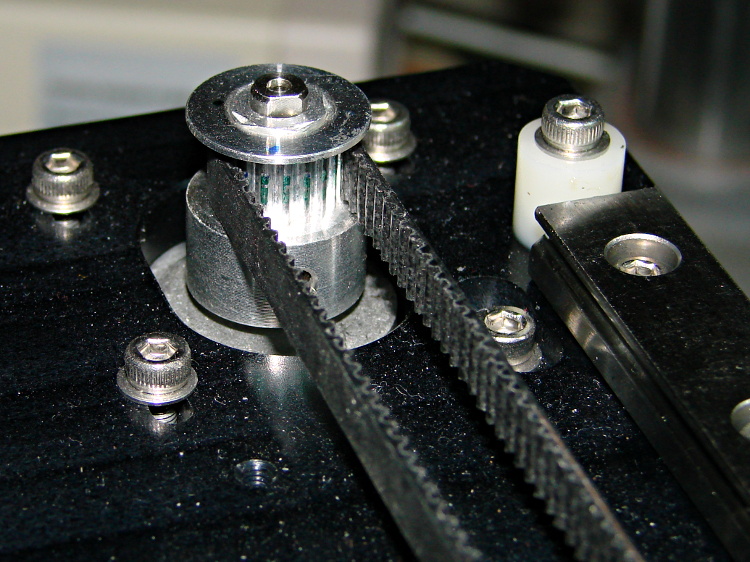
Each revolution requires 3200 steps, so the X and Y stages move at:
88.888 step/mm = 3200 step / 36 mm
Makergear uses 88.88 step/mm, rather than the rounded 88.89, but the difference across 250 mm amounts to 2.5 steps, so it doesn’t matter.
For the Z axis, the four-start leadscrew moves the stage 8 mm, so:
400 step/mm = 3200 step / 8 mm
The situation with the extruder drive isn’t quite so clear, because the actual filament movement depends on the effective diameter of the drive pulley’s teeth engaging the filament. Mechanically, the extruder motor runs a 5:1 gearbox, so each drive pulley rotation requires 16000 (micro)steps.
The filament drive pulley has 22 teeth and a 12.0 mm OD = 37.7 mm circumference:
424.4 step/mm = 16000 step / 37.7 mm

That’s measured at the tooth tip. If you think of the filament as being a belt, then you’d expect it to move precisely that distance… except that the teeth dig into the filament, so the effective diameter comes out a bit smaller and the step/mm value a bit higher.
Makergear’s default 471.5 step/mm is, indeed, larger, but the ratio of the two values seems both oddly familiar and eerily exact:
0.900 = 424.4 / 471.5
The “packing density” Fudge Factor (yclept extrusion multiplier by slic3r) that accounts for the difference between the drive gear OD and the actual filament motion runs around 0.9, with passionate arguments justifying more specific values. It looks like Makergear baked that number into the firmware, so the nominal slic3r extrusion multiplier should be pretty close to 1.0.
After a few quick measurements while getting the printer running, I settled on extrusion multiplier = 0.9, so the actual step/mm value in effect for the extruder works out to:
424.4 = (471.5 step/mm) * 0.9
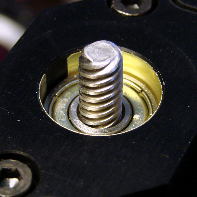
Now, that would seem to imply that the filament skates along the top of teeth, but that’s not the case:

So, for whatever reason, the effective diameter of the drive pulley matches its actual OD. That will surely vary with a number of imponderables, including the setting for the clamp screw holding the bearing against the filament and drive pulley.
Being that type of guy, I favor baking the actual drive pulley OD into the firmware (because I can actually measure that value), then using the extrusion multiplier to account for the difference. I’ve heard cogent arguments to the contrary, but, for my purposes, the proper value for the extruder should 424.4 step/mm, with a corresponding extrusion multiplier change to 1.00 in slic3r’s configuration.
I wouldn’t be surprised in the least to discover:
- I’m multiplying where I should be dividing (or the other way around)
- There’s a squaring / rooting operation hidden somewhere in there (area vs length)
- Another obvious blunder has tripped me up
Selah.

Comments
15 responses to “M2 vs. Marlin: Step/mm Calculations”
Since the filament is driven tangential to the gear wouldn’t distance per rev be equal to the gears diameter? When traveling radially around a gear the ID and OD of the belt travels at different rates which equates to the pitch circle. Since the filament is traveling linearly it will move at the rate of the gears/splines OD. I think…
The gear drive teeth don’t crunch linearly into the filament, so the perimeter doesn’t move quite as far as you’d expect.
That multiplier turns out to be the only free variable in the calculations, so it must also include all the other Fudge Factors. I’m not convinced there’s much volume vanishing in water vapor and suchlike, though.
I definitely want a closer look at how all that stuff interacts…
I can’t convince myself that the depth to which the teeth bite into the filament matters. Consider the case where we’re looking at the gear and the filament along the gear’s axis of rotation. The left edge of the filament, the centerline of the filament, and the right edge of the filament all must move downward at the same rate, since they’re (approximately) inelastically connected to each other. Likewise, the tips of the gear teeth must move down at a fixed rate when they are tangent to the vertical. No matter how far you shove those tips into the filament, they are still moving at that rate, therefore the entire filament must move at that rate. The depth only affects how much you distort the triangular notches you’re cutting into the side of the filament, but not the rate of motion. I think. (I’m sure there’s lots of other fudge factors laying in wait. But I’m not persuaded this is one of them.)
The displaced plastic may lengthen the the filament, stretching the “undisturbed” filament on the bearing side (away from the drive gear) lengthwise. In effect, the filament passes through a constriction that also moves it downward and, because the drive occurs at the constriction, the gear moves less filament than you’d expect.
But, frankly, I’m not convinced, either… and I certainly don’t have any numbers!
(If we modeled the filament as a rack and the drive gear as a pinion, the rack would always move at exactly the rates of the gear tooth at the DP tangent to the vertical, no matter how much additional depth the rack teeth had…)
This all sounds familiar. At one time J head hot ends were being shipped with tips drilled a few thou less than specified. The reasoning was to account for tool wear…. A diameter of 0.332 mm reduces the cross section of a 0.35 mm the orifice by 10%. Push the same volume through both and the smaller diameter extruder will be 10% longer. That is only 7/10000 of an inch variance. Could easily be attributed to tooling wear during the drilling process. I have no idea how you would QC a bore that small.
There are folks who routinely work to those tolerances, but I’m not among them. The best I could do would be to measure the result and calibrate around it, which is what we all do now, anyway.
If I were drilling nozzles, I’d be happy to just get the hole, any hole, through the nozzle!
[…] « M2 vs. Marlin: Step/mm Calculations […]
Aha! I hadn’t conisdered that, but that’s trivial to test: chop off exactly 100mm of filament, run it through the extruder drive (after removing the heater/nozzle), and measure how long it is when it comes out…
‘Small’ holes are typically QCed with plug gauges, usually having two ends – a Go and a No-Go diameter plug: http://en.wikipedia.org/wiki/Go/no_go_gauge
Typical 3D printed holes aren’t nearly tidy enough for a plug gauge, although that would certainly highlight the problem: they’d all be solidly No-Go!
The results from a hole-and-post test object give some idea of the size issue.
Polygonal holes give good accuracy, even though circular holes become triangles, squares, and other peculiar shapes. A plug gauge should give the right answer despite the shape: the polygons circumscribe the circles!
[…] reset the Marlin constants based on first principles, per the notes on distance, speed, and acceleration, so they’re not representative of the as-shipped M2 firmware. […]
Ed,
Are you near Highland, Michigan?
Nope: Highland, NY, halfway up the Hudson River from NYC, across from Poughkeepsie, NY, which is nowhere near Poughkeepsie, AR.
All the good names were used up, I suppose…
[…] printer mechanics determine the step/mm values for all four axes: X, Y, Z, and the extruder. The effective diameter of the “gear” driving the filament into the extruder seems […]