The M2 filament drive works surprisingly well. The OD of the curved section around the drive gear could easily be another few millimeters larger, which would put the mounting screw holes completely within the plastic perimeter:

I haven’t changed the position of the filament compression screw and the default setting produces a really aggressive grip on the filament; the picture shows the deep track from the drive gear in the natural-color PLA filament along the bottom of the opening. That may be entirely too much of a good thing, but I’ll leave well enough alone for now.
Makergear had scraped out the recess that accepts the end of the motor gearbox housing, but it still didn’t quite fit the motor’s snout, so I continued the scraping job until the drive sat square on the end of the gearbox. It mounts to the gearbox with three screws: the gearbox has four threaded holes, but the fourth screw would pass through an inconvenient spot above the bearing / below the compression screw / beside the filament / inside the clamp arm.
Perhaps rotating the motor slightly would reposition the mounting holes a bit better? Disadvantage: hard to make the extruder sit vertically with a crooked motor. Maybe integrate the extruder with the motor mount, so the vertical reference comes from the X stage linear slide platform and the mount forces the proper motor and extruder alignment?
The filament compression screw is offset rearward from the filament, so the upper part of the clamp must apply serious torque through its plastic body to the bearing pressing the filament against the drive gear:
I think a spring-loaded bearing would work better, with force applied through a pair of springs bracketing the bearing to reduce the single-point load and torque, with a hinge pin below the bearing. The Wade-ScribbleJ bearing clamp on the Thing-O-Matic has worked perfectly since I installed it, but there are now simpler designs out there that should be adaptable.
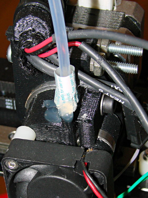
The twist of paper embedded in a blob of hot-melt glue encourages the filament guide tube to stand up straight and not flop over during reversals. That should be somewhat longer and fit neatly around the guide; it should be part of the filament drive body. This end of the guide tube should not be anchored, so it can pop upward when the filament reverses; there’s no need to push the filament backwards through a fixed guide tube at full reversal speed.
The drive came pre-assembled to and aligned with the hot end, here seen without the paper / glue guide after the first-pass assembly:

I want to insert strain gauges between the mount and the extruder barrel in order to measure the force applied to the hot end during extrusion, but it’s not clear how to do that with this design. I think I must build a bench model that extrudes a plastic tangle into air before I understand the problems. Again, an integrated motor + extruder mount might work better.
The PTFE (?) filament guide tube had both ends slightly crimped from the pliers that cut it off the reel, which isn’t unexpected. I reshaped / reamed the ends of the tube to pass the filament without undue friction. There’s still a bit too much friction, methinks, but it doesn’t pose a problem yet.
The spool holder and filament guide don’t match the drawings at all; some discussions in the Google Group indicate this design works much better than the original, fiercely complex, design.
The end of the filament guide tube over the spool also tends to flop over and bend the filament, so I blobbed enough hot melt glue around it on the guide bracket to both anchor it and enforce good alignment. The red cable tie holds the blob in place, as there’s no mechanical interlock on the bracket for the glue to grab:
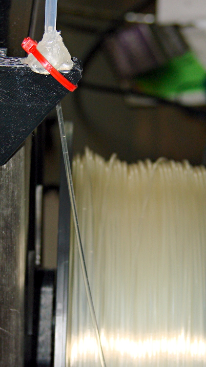
Another design for a much longer bracket positions the guide tube over the spool’s midline, which should reduce the snap when the filament slips over a bunching on one side or the other. I think I’ll gimmick up something with an integral alignment doodad for the filament tube.
The guide tube reorients the filament to be tangential to the spool, with the bracket providing the reaction force required to hold the guide tube in place while the filament transmits force from the extruder motor that unrolls the filament. Given that we know exactly how much filament travels into the extruder, we could add a motor drive to unroll exactly that amount from the spool and maintain the length of the filament loop without a guide tube. At higher feed rates, that would allow the extruder drive to feed filament into the hot end without any drag, thus eliminating any effects not related to the actual extrusion process. I like that sound…

Comments
2 responses to “Makergear M2: Filament Drive”
Since you are already doing mods, here are some items high up on my personal list.
http://trinitylabs.com/products/hobbed-pulley Note this comes in an 8mm bore which is what the shaft of the geared stepper you have is.
There are at least 2 alternate hot ends that attach in the exact same “groove mount” you have now.
http://trinitylabs.com/products/trinity-metalmagma-all-metal-high-temp-hotend
http://trinitylabs.com/products/j-head-mk-v-hot-end
FWIW, the Makgergear hot end has too long of a heated path in my mind. This hurts retraction and ooze. The entire M6 brass tube will be at temps high enough to melt PLA and thus any reversal results in soft PLA being sucked into the pinchwheel system and then that’s the end of your print. Another Hot end that likely just slips in https://groups.google.com/forum/?fromgroups#!topic/pche_v01-testers/ngpjZzJth_4
I like the fine hobbed teeth on the drive, which seem better suited to 1.7 mm filament than the chunky teeth on the Makergear drive. Gotta get some; thanks for the tip.
I want to add thermocouples along the length of that tube to see what’s going on inside. Then we can figure out how much heat needs removing, how that affects the heater duty cycle, and stuff like that. But it’ll be easier to do that with LinuxCNC handling the interfaces, because I can synchronize measurements with the driver outputs.
Numbers. We need numbers!
Then we can do it better… [grin]
It’s running fine at 1 mm retraction, so the filament going back into the drive is nice and cool: it’s still within the plastic extruder frame. I agree that the filament within the tube is probably gummy. More study seems needed…