-
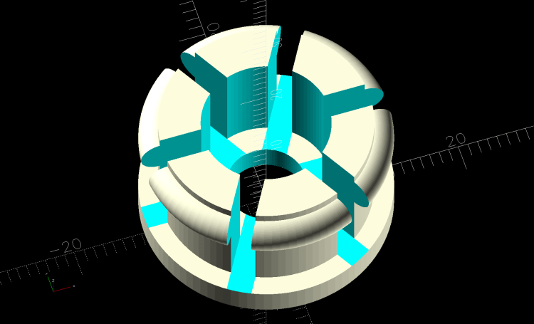
The compressed / bent segments will gradually relax inside the legs
-
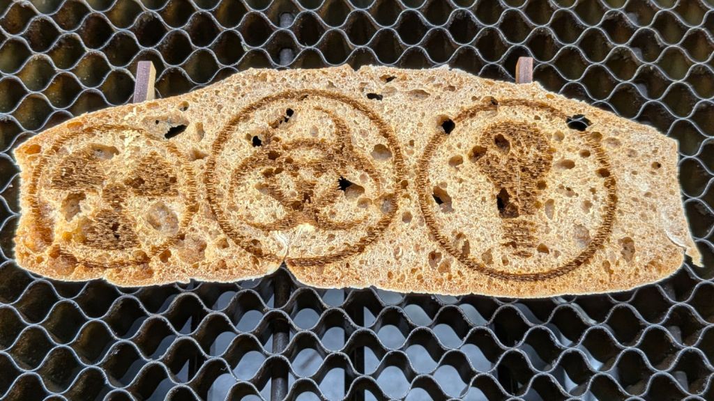
It’s good stinky provolone, so its taste remained undamaged
-
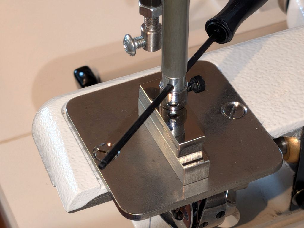
Whoever aligns the machines doesn’t care about needle orientation
-
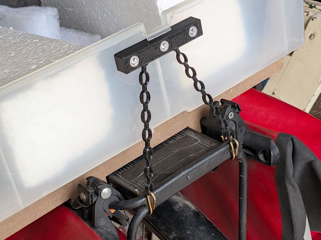
Rectangular blocks anchoring chains ending in hooks bashed from an old coathanger
-
Riding on NYS DOT roads, where bicycling is always an uninterrupted delight

-
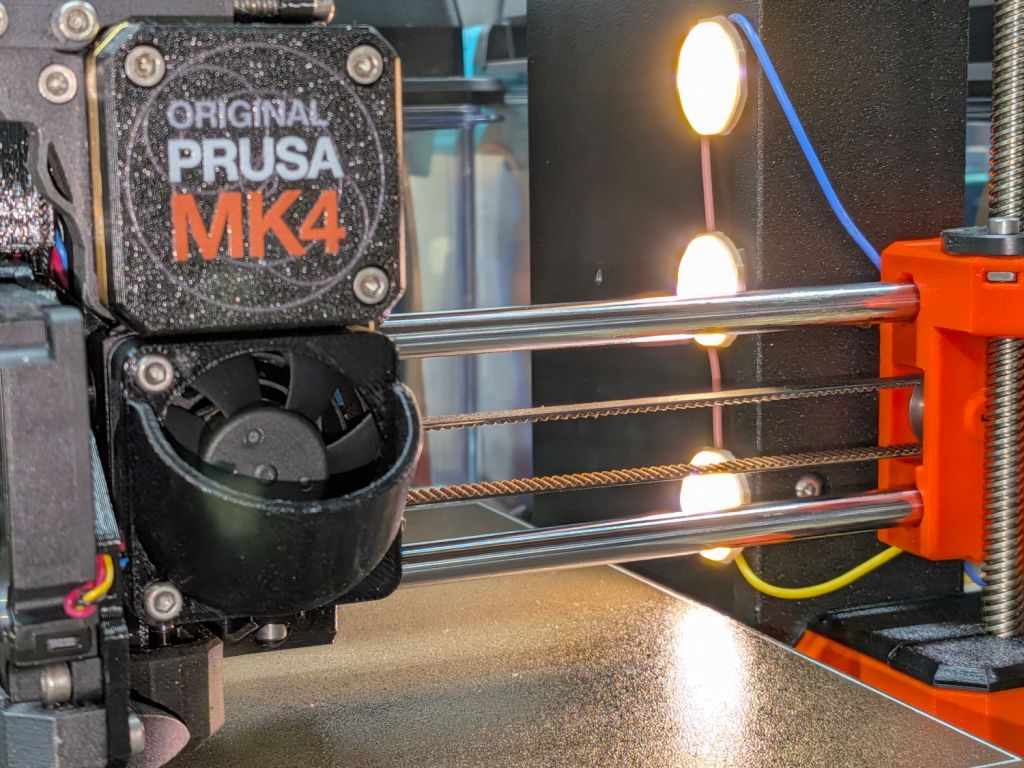
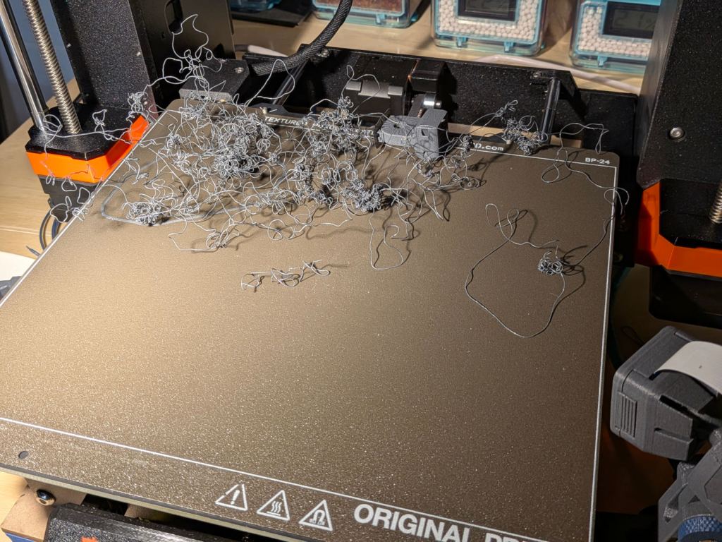
The nozzle was busily adding to the tangle
-
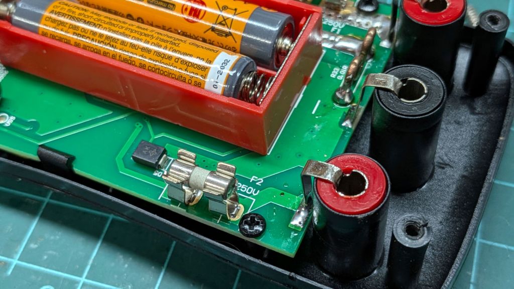
Definitely within whatever power rating they should have