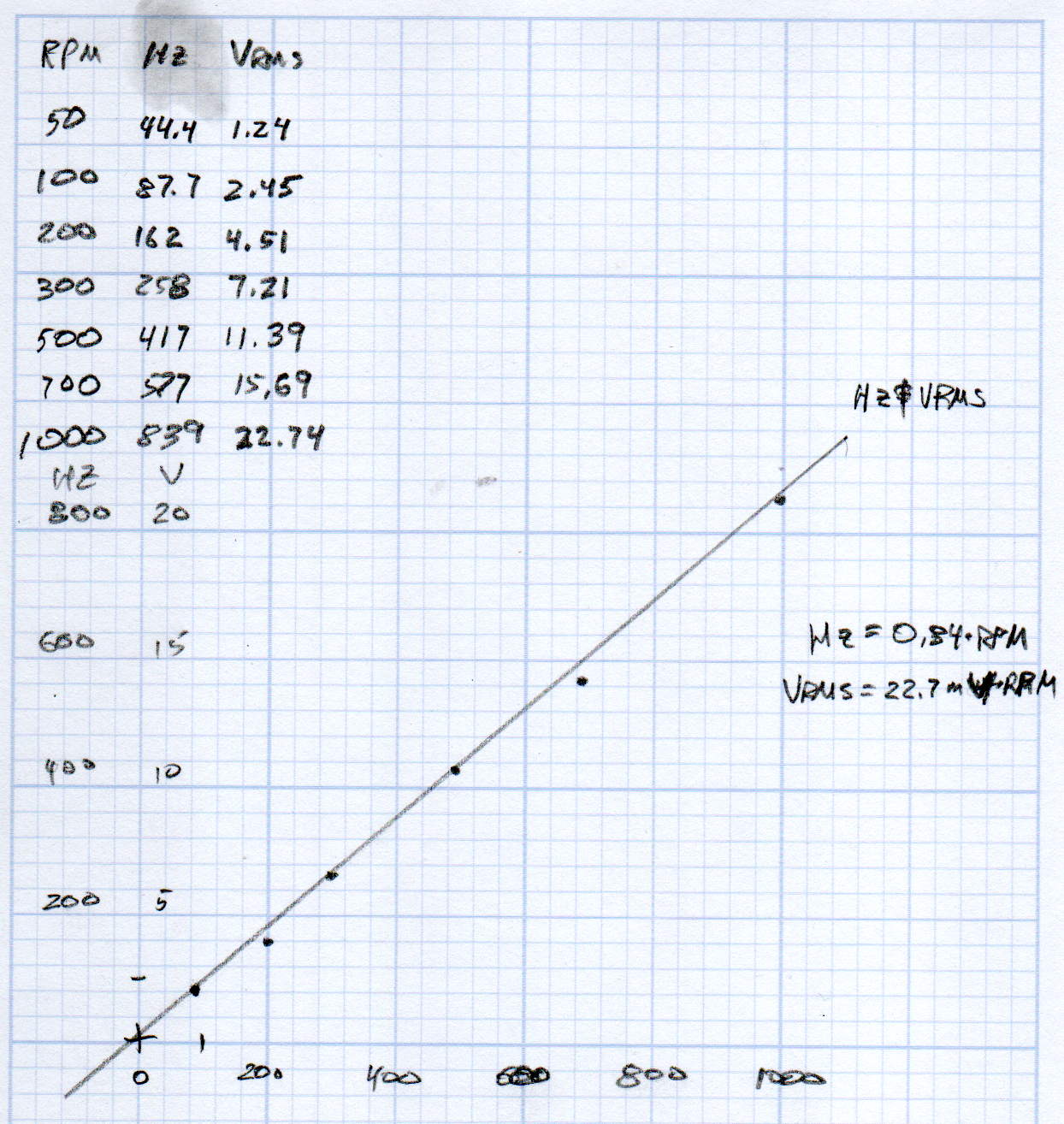
A plot of the back EMF for an Automation Technology KL17H248-15-4A stepper motor looks like I’m making stuff up again:
Maybe the only questions I ask are ones with linear solutions?
Anyhow, the data comes from the Z-axis motor in the lathe:
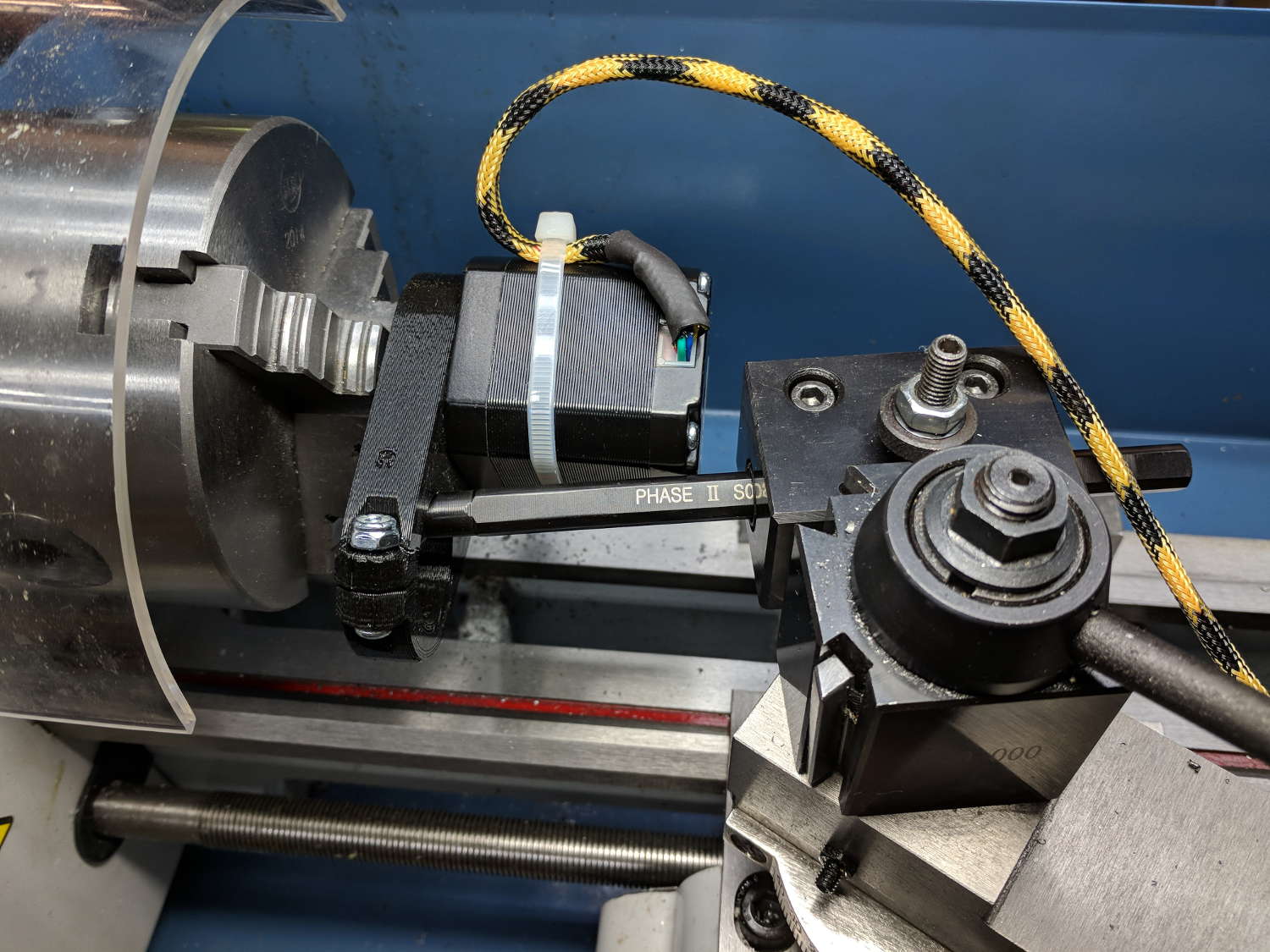
Scary-looking, but reasonably safe. The chuck holds the motor shaft so it’s not going anywhere, the boring bar prevents any rotation, and the motor bearings do exactly what they’re supposed to. Shorting the motor leads would definitely put a hurt on the PLA frame, so I didn’t do that.
The scope sat on the floor beside the lathe, capturing waveforms and doing calculations:

Some waveforms look bent:

I asked the scope to measure the RMS voltage, rather than the peak, because it’s less sensitive to distortions.
Each winding produces one electrical cycle across four mechanical full steps, with the windings in quadrature. One shaft revolution thus produces 200 / 4 = 50 electrical cycles, so converting from shaft RPM into electrical cycles/s goes a little something like this:
Electrical cycles/s = (shaft rev/min) * (50 cycles/rev) / 60 (s/min)
Which works out to a tidy 0.833 Hz/RPM, basically spot on the last data point’s 839 Hz at 1000 RPM.
The motivation for this comes from the third column in the scribbles: back EMF = 22.7 mVrms/RPM = 32 mVpk/RPM.
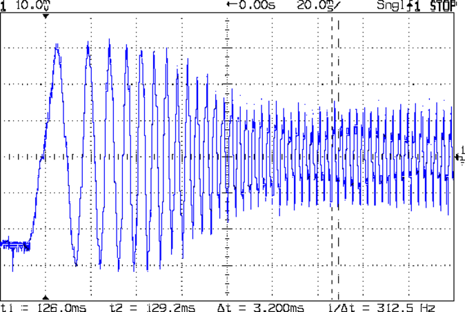
A rapid move at 12 k mm/min = 200 mm/s shows the motor current collapsing to the ragged edge of not working:
Converting motor speed to shaft RPM:
RPM = (axis mm/s) / (32 mm/rev) * (60 s/min)

RPM = (axis mm/min) / (32 mm/rev)
So the shaft turns at 375 RPM when the X axis moves at 12 k mm/min, with each motor generating 8.5 Vrms = 12 Vpk of back EMF.
The MPCNC wires the two motors on each axis in series, so the 24 V power supply faces 24 V of back EMF (!) from both motors, leaving exactly nothing to push the winding current around. Because the highest EMF occurs at the zero crossing points of the (normal) winding current, I think the current peaks now occur there, with the driver completely unable to properly shape the current waveform.
What you see in the scope shot is what actually happens: the current stabilizes at a ragged square-ish wave at maybe 300 mA (plus those nasty spikes). More study is needed.

Comments
4 responses to “MPCNC: Stepper Motor Back EMF”
I wonder if the back-emf waveform at any given velocity is the best waveform to use for micro stepping.
I think the bent waveforms may be transient events from my … casual … test setup. The PLA motor mount (a.k.a., the top of the MPCNC Z-axis stack) isn’t absolutely square to the motor and tended to wobbulate ever so slightly as the shaft turned. I tried to take representative pix, limited by my desire to not have, oh, the chuck sweep up the wires.
I expect some cycle-to-cycle variation due to winding and rotor imperfections, although they’re surely small compared to the stepper driver’s rough-and-ready sine wave approximation + PWM current tweaking.
Bottom line: no clue!
The ETC MicroVision lighting control console uses a stepper as an encoder and it’s the best feeling encoder I’ve ever used. The magnetic detents are sublime.
IIRC, the LinuxCNC folks had some DIY stepper-as-encoder designs, using low-value resistors for both detents and voltage outputs. I should get a handful of miniature motors and try it out.
Thanks for the suggestion!