The object of soldering all 40 wires in the 5 m hank of ribbon cable in series is to build a 40 turn loop antenna to receive LF radio signals like WWVB at 60 kHz. The antenna, being basically a big coil of wire, will have an inductance that depends on its layout, so putting a capacitor in parallel turns it into a resonant tank circuit. Given a particular layout (and, thus, an inductance), you can choose the capacitor to make the antenna resonant at whatever frequency you need (within reason).
With the joints soldered & reinforced with epoxy, the inductance across all 40 turns:
- 535 µH – rolled into a compact bundle
- 6.66 mH – vaguely circular loop on the concrete floor
- 5.50 mH – lumpy rectangle on the concrete floor
Back in a slightly different circular layout on the floor:
- 6.8 mH – across all 40 turns, as above
- 2.0 mH – across either set of 20 turns from the center tap
Given that inductance varies as the square of the number of turns, you’d expect a factor of four between those two inductances, but that’s not how it worked out.
Hanging the loop from a pair of screws in the floor joists to make a droopy rectangle-oid shape and driving it from a 600 Ω signal generator through a 10 kΩ resistor, it’s self-resonant at 213 kHz. Repeating that with a 470 kΩ resistor drops the resonance to 210 kHz, which isn’t different enough to notice and surely has more to do with my moving the loop while dinking with resistors.
Adding parallel capacitance (measured with an LCR meter, just to be sure) changes the resonance thusly:
- 9.9 nF → 20 kHz
- 900 pF → 64 kHz
- 400 pF → 87 kHz
- 250 pF → 108 kHz
- none → 213 kHz
Because the resonant frequency varies inversely as the square root of the capacitance, halving the resonant frequency means you’ve increased the capacitance by a factor of four. Because 250 pF halves the frequency (mostly kinda sorta close enough), the loop’s stray capacitance must be about 1/3 of that: 83 pF.
Yeah, 1/3, not 1/4: the additional capacitance adds to the stray capacitance, so it goes from 83 pF to 250 + 83 pF = 333 pF, which is four times 83 pF.
(If that sound familiar, it’s similar to the resonant snubber calculation.)
The self-resonant frequency of 213 kHz and the 83 pF stray capacitance determines the loop inductance:
L = 1/((2π · 213 kHz)^2 · 83 pF) = 6.9 mH
Pretty close to the measured value from the floor, I’d say.
To resonate the antenna at 60 kHz, the total capacitance must be:
60 kHz = 1/(2π · sqrt(6.9 mH · C)) → C = 1050 pF
Which means an additional 1050 – 83 = 970-ish pF should do the trick, which is about what you’d expect from the 64 kHz resonance with the 900 pF cap above. I paralleled pairs of caps until it resonated at 59.9 kHz.
The -3 dB points (voltage = 1/sqrt(2) down from the peak) turned out to be 58.1 and 60.1 kHz, so my kludged caps are slightly too large or, once again, I nudged the loop.
Figuring Q = (center frequency) / bandwidth = 59.1 / 2 = 30, which works out close enough to Q = X / R = 2600 / 80 = 33 to be satisfying. Using standard 26-ish AWG ribbon cable, rather than crappy 31-ish AWG eBay junk, would double the conductor area, halve the series resistance, and double the Q. Faced with that much resistance, I’m not sure better caps would make any difference.
Attaching the spectrum analyzer through a 470 Ω resistor to reduce the load:
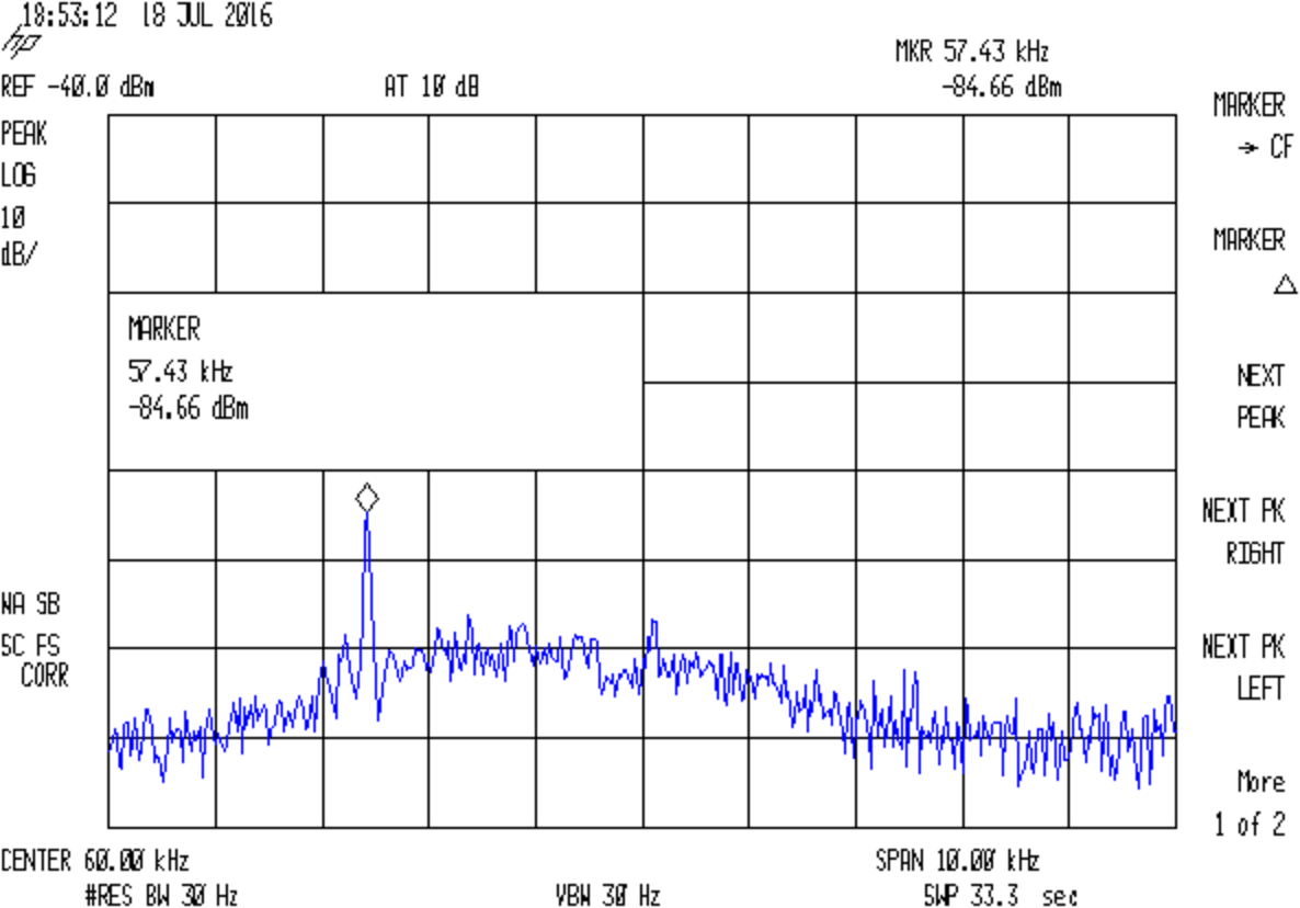
I’d love to believe that big peak over on the left at 57.1 kHz is WWVB, but it’s not.
What’s more important: the broad hump between 56 and 62 kHz, where the increased amount of background hash suggests the antenna really is resonant, with a center frequency around 59 kHz. The -3 dB points might be 57 and 61 kHz, but at 10 dB/div with 5 dB of hash, I’d be kidding myself.
Dang, I love it when the numbers work out!
It’s faintly possible the spectrum analyzer calibration is off by 2.5 kHz at the low end of its range. The internal 300 MHz reference shows 299.999925 and it puts FM stations where they should be, but the former could be self-referential error and the latter lacks enough resolution to be comforting. I must fire up the GPS frequency reference, let it settle for a few days, see whether it produces 10.000000 MHz like it should, then try again.
The original measurements:


Comments
2 responses to “LF Loop Antenna: 60 kHz Tuning”
[…] yeah, that signal at 57-ish kHz really isn’t at 60.000 […]
[…] the loop antenna requires an external capacitor around 1000 pF. Paralleling a 120 pF fixed cap with both sections […]