Confronted with a puzzling failure, I decided to perform some long-delayed tweaking…
The folks at Makergear send me (and several others) a new filament drive gear for testing. It has smaller splines / teeth and produces a much finer mark on the filament:
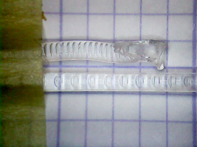
The obvious stripped section on the right comes from finger-fumbling an absurdly large extrusion distance (something like, mmm, 1450 mm) with a high extrusion speed. Not the fault of the drive gear, that’s for sure!
I remeasured the actual filament length extruded to recompute Marlin’s STEPSPERMM configuration constant. After rediscovering the awkward fact that, when you change that value with an M92 command, Marlin doesn’t recompute the current extruder position, so the next manual extrusion will move a random amount of filament in a random direction, the value eventually converged to 476.9 steps/mm.
I intended to put the M92 in Slic3r’s startup G-Code, but the prospect of random extrusions suggested that now was a great time to update the firmware; again demonstrating that no good idea goes unpunished.
The most recent Marlin version, 1.1.0-RC5 (clearly labeled “Not for production use – use with caution!”), had been released a few hours earlier, so I fetched that and tweaked the configuration files as before.
The firmware now includes thermal runaway / thermistor failure protection for both the bed and hot end. Increasing the two THERMAL_PROTECTION hysteresis values to 6 °C seems to work well.
It also includes a CONTROLLERFAN output that can go active when any stepper is enabled, then off after predetermined time. Setting that to Pin 6 and 30 seconds means the whining fan (it’s a ball bearing replacement in an aerodynamically poor location) in the control box goes off when it’s not needed.
Bumping DEFAULT_STEPPER_DEACTIVE_TIME to 600 seconds means the motors don’t time out while waiting for the platform to reach operating temperature.
Increasing the HOMING_FEEDRATE for the Z-axis to 60*60 mm/min causes it to whack the lever a bit harder and overtravel slightly more. The Z Offset ended up at -2.15 mm, based on the calibration cubes below.
Running a PID calibration on the V4 hot end produced slightly different values: P=17.41, I=1.02, D=74.44. Hardcoding those into the config file does not override the values already stored in EEPROM: you must manually set them with M301, then use M500 to program the EEPROM.
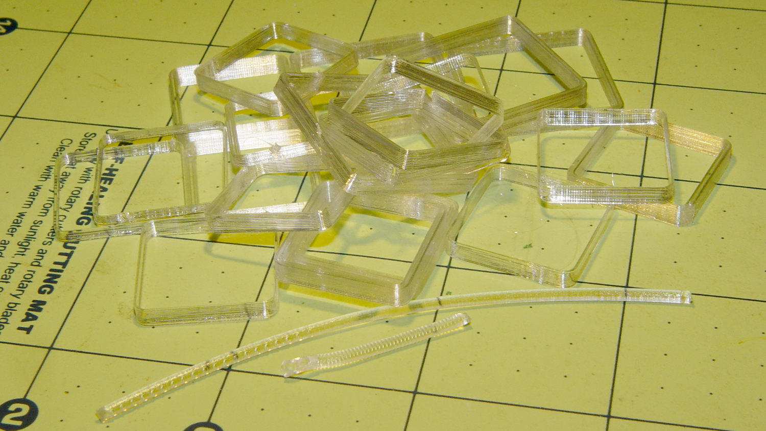
A few Calibration Box iterations settled settled the Extrusion Multiplier at a convenient 1.00 with the new drive gear:
All in all, that whole process went much more smoothly than I expected.
The config files as GitHub gists:
| /** | |
| * Marlin 3D Printer Firmware | |
| * Copyright (C) 2016 MarlinFirmware [https://github.com/MarlinFirmware/Marlin] | |
| * | |
| * Based on Sprinter and grbl. | |
| * Copyright (C) 2011 Camiel Gubbels / Erik van der Zalm | |
| * | |
| * This program is free software: you can redistribute it and/or modify | |
| * it under the terms of the GNU General Public License as published by | |
| * the Free Software Foundation, either version 3 of the License, or | |
| * (at your option) any later version. | |
| * | |
| * This program is distributed in the hope that it will be useful, | |
| * but WITHOUT ANY WARRANTY; without even the implied warranty of | |
| * MERCHANTABILITY or FITNESS FOR A PARTICULAR PURPOSE. See the | |
| * GNU General Public License for more details. | |
| * | |
| * You should have received a copy of the GNU General Public License | |
| * along with this program. If not, see <http://www.gnu.org/licenses/>. | |
| * | |
| */ | |
| /** | |
| * Configuration.h | |
| * | |
| * Basic settings such as: | |
| * | |
| * – Type of electronics | |
| * – Type of temperature sensor | |
| * – Printer geometry | |
| * – Endstop configuration | |
| * – LCD controller | |
| * – Extra features | |
| * | |
| * Advanced settings can be found in Configuration_adv.h | |
| * | |
| */ | |
| #ifndef CONFIGURATION_H | |
| #define CONFIGURATION_H | |
| #include "boards.h" | |
| #include "macros.h" | |
| //=========================================================================== | |
| //============================= Getting Started ============================= | |
| //=========================================================================== | |
| /** | |
| * Here are some standard links for getting your machine calibrated: | |
| * | |
| * http://reprap.org/wiki/Calibration | |
| * http://youtu.be/wAL9d7FgInk | |
| * http://calculator.josefprusa.cz | |
| * http://reprap.org/wiki/Triffid_Hunter%27s_Calibration_Guide | |
| * http://www.thingiverse.com/thing:5573 | |
| * https://sites.google.com/site/repraplogphase/calibration-of-your-reprap | |
| * http://www.thingiverse.com/thing:298812 | |
| */ | |
| //=========================================================================== | |
| //============================= DELTA Printer =============================== | |
| //=========================================================================== | |
| // For a Delta printer replace the configuration files with the files in the | |
| // example_configurations/delta directory. | |
| // | |
| //=========================================================================== | |
| //============================= SCARA Printer =============================== | |
| //=========================================================================== | |
| // For a Scara printer replace the configuration files with the files in the | |
| // example_configurations/SCARA directory. | |
| // | |
| // @section info | |
| #if ENABLED(USE_AUTOMATIC_VERSIONING) | |
| #include "_Version.h" | |
| #else | |
| #include "Default_Version.h" | |
| #endif | |
| // User-specified version info of this build to display in [Pronterface, etc] terminal window during | |
| // startup. Implementation of an idea by Prof Braino to inform user that any changes made to this | |
| // build by the user have been successfully uploaded into firmware. | |
| #define STRING_CONFIG_H_AUTHOR "(Ed Nisley KE4ZNU)" // Who made the changes. | |
| #define SHOW_BOOTSCREEN | |
| #define STRING_SPLASH_LINE1 SHORT_BUILD_VERSION // will be shown during bootup in line 1 | |
| //#define STRING_SPLASH_LINE2 STRING_DISTRIBUTION_DATE // will be shown during bootup in line 2 | |
| // @section machine | |
| // SERIAL_PORT selects which serial port should be used for communication with the host. | |
| // This allows the connection of wireless adapters (for instance) to non-default port pins. | |
| // Serial port 0 is still used by the Arduino bootloader regardless of this setting. | |
| // :[0,1,2,3,4,5,6,7] | |
| #define SERIAL_PORT 0 | |
| // This determines the communication speed of the printer | |
| // :[2400,9600,19200,38400,57600,115200,250000] | |
| #define BAUDRATE 115200 | |
| // Enable the Bluetooth serial interface on AT90USB devices | |
| //#define BLUETOOTH | |
| // The following define selects which electronics board you have. | |
| // Please choose the name from boards.h that matches your setup | |
| #ifndef MOTHERBOARD | |
| #define MOTHERBOARD BOARD_RAMBO | |
| #endif | |
| // Optional custom name for your RepStrap or other custom machine | |
| // Displayed in the LCD "Ready" message | |
| #define CUSTOM_MACHINE_NAME "Hotrod M2" | |
| // Define this to set a unique identifier for this printer, (Used by some programs to differentiate between machines) | |
| // You can use an online service to generate a random UUID. (eg http://www.uuidgenerator.net/version4) | |
| //#define MACHINE_UUID "00000000-0000-0000-0000-000000000000" | |
| // This defines the number of extruders | |
| // :[1,2,3,4] | |
| #define EXTRUDERS 1 | |
| // Offset of the extruders (uncomment if using more than one and relying on firmware to position when changing). | |
| // The offset has to be X=0, Y=0 for the extruder 0 hotend (default extruder). | |
| // For the other hotends it is their distance from the extruder 0 hotend. | |
| //#define EXTRUDER_OFFSET_X {0.0, 20.00} // (in mm) for each extruder, offset of the hotend on the X axis | |
| //#define EXTRUDER_OFFSET_Y {0.0, 5.00} // (in mm) for each extruder, offset of the hotend on the Y axis | |
| //// The following define selects which power supply you have. Please choose the one that matches your setup | |
| // 1 = ATX | |
| // 2 = X-Box 360 203Watts (the blue wire connected to PS_ON and the red wire to VCC) | |
| // :{1:'ATX',2:'X-Box 360'} | |
| #define POWER_SUPPLY 1 | |
| // Define this to have the electronics keep the power supply off on startup. If you don't know what this is leave it. | |
| //#define PS_DEFAULT_OFF | |
| // @section temperature | |
| //=========================================================================== | |
| //============================= Thermal Settings ============================ | |
| //=========================================================================== | |
| // | |
| //–NORMAL IS 4.7kohm PULLUP!– 1kohm pullup can be used on hotend sensor, using correct resistor and table | |
| // | |
| //// Temperature sensor settings: | |
| // -3 is thermocouple with MAX31855 (only for sensor 0) | |
| // -2 is thermocouple with MAX6675 (only for sensor 0) | |
| // -1 is thermocouple with AD595 | |
| // 0 is not used | |
| // 1 is 100k thermistor – best choice for EPCOS 100k (4.7k pullup) | |
| // 2 is 200k thermistor – ATC Semitec 204GT-2 (4.7k pullup) | |
| // 3 is Mendel-parts thermistor (4.7k pullup) | |
| // 4 is 10k thermistor !! do not use it for a hotend. It gives bad resolution at high temp. !! | |
| // 5 is 100K thermistor – ATC Semitec 104GT-2 (Used in ParCan & J-Head) (4.7k pullup) | |
| // 6 is 100k EPCOS – Not as accurate as table 1 (created using a fluke thermocouple) (4.7k pullup) | |
| // 7 is 100k Honeywell thermistor 135-104LAG-J01 (4.7k pullup) | |
| // 71 is 100k Honeywell thermistor 135-104LAF-J01 (4.7k pullup) | |
| // 8 is 100k 0603 SMD Vishay NTCS0603E3104FXT (4.7k pullup) | |
| // 9 is 100k GE Sensing AL03006-58.2K-97-G1 (4.7k pullup) | |
| // 10 is 100k RS thermistor 198-961 (4.7k pullup) | |
| // 11 is 100k beta 3950 1% thermistor (4.7k pullup) | |
| // 12 is 100k 0603 SMD Vishay NTCS0603E3104FXT (4.7k pullup) (calibrated for Makibox hot bed) | |
| // 13 is 100k Hisens 3950 1% up to 300°C for hotend "Simple ONE " & "Hotend "All In ONE" | |
| // 20 is the PT100 circuit found in the Ultimainboard V2.x | |
| // 60 is 100k Maker's Tool Works Kapton Bed Thermistor beta=3950 | |
| // 70 is the 100K thermistor found in the bq Hephestos 2 | |
| // | |
| // 1k ohm pullup tables – This is not normal, you would have to have changed out your 4.7k for 1k | |
| // (but gives greater accuracy and more stable PID) | |
| // 51 is 100k thermistor – EPCOS (1k pullup) | |
| // 52 is 200k thermistor – ATC Semitec 204GT-2 (1k pullup) | |
| // 55 is 100k thermistor – ATC Semitec 104GT-2 (Used in ParCan & J-Head) (1k pullup) | |
| // | |
| // 1047 is Pt1000 with 4k7 pullup | |
| // 1010 is Pt1000 with 1k pullup (non standard) | |
| // 147 is Pt100 with 4k7 pullup | |
| // 110 is Pt100 with 1k pullup (non standard) | |
| // 998 and 999 are Dummy Tables. They will ALWAYS read 25°C or the temperature defined below. | |
| // Use it for Testing or Development purposes. NEVER for production machine. | |
| //#define DUMMY_THERMISTOR_998_VALUE 25 | |
| //#define DUMMY_THERMISTOR_999_VALUE 100 | |
| // :{ '0': "Not used", '4': "10k !! do not use for a hotend. Bad resolution at high temp. !!", '1': "100k / 4.7k – EPCOS", '51': "100k / 1k – EPCOS", '6': "100k / 4.7k EPCOS – Not as accurate as Table 1", '5': "100K / 4.7k – ATC Semitec 104GT-2 (Used in ParCan & J-Head)", '7': "100k / 4.7k Honeywell 135-104LAG-J01", '71': "100k / 4.7k Honeywell 135-104LAF-J01", '8': "100k / 4.7k 0603 SMD Vishay NTCS0603E3104FXT", '9': "100k / 4.7k GE Sensing AL03006-58.2K-97-G1", '10': "100k / 4.7k RS 198-961", '11': "100k / 4.7k beta 3950 1%", '12': "100k / 4.7k 0603 SMD Vishay NTCS0603E3104FXT (calibrated for Makibox hot bed)", '13': "100k Hisens 3950 1% up to 300°C for hotend 'Simple ONE ' & hotend 'All In ONE'", '60': "100k Maker's Tool Works Kapton Bed Thermistor beta=3950", '55': "100k / 1k – ATC Semitec 104GT-2 (Used in ParCan & J-Head)", '2': "200k / 4.7k – ATC Semitec 204GT-2", '52': "200k / 1k – ATC Semitec 204GT-2", '-3': "Thermocouple + MAX31855 (only for sensor 0)", '-2': "Thermocouple + MAX6675 (only for sensor 0)", '-1': "Thermocouple + AD595", '3': "Mendel-parts / 4.7k", '1047': "Pt1000 / 4.7k", '1010': "Pt1000 / 1k (non standard)", '20': "PT100 (Ultimainboard V2.x)", '147': "Pt100 / 4.7k", '110': "Pt100 / 1k (non-standard)", '998': "Dummy 1", '999': "Dummy 2" } | |
| #define TEMP_SENSOR_0 1 | |
| #define TEMP_SENSOR_1 0 | |
| #define TEMP_SENSOR_2 0 | |
| #define TEMP_SENSOR_3 0 | |
| #define TEMP_SENSOR_BED 1 | |
| // This makes temp sensor 1 a redundant sensor for sensor 0. If the temperatures difference between these sensors is to high the print will be aborted. | |
| //#define TEMP_SENSOR_1_AS_REDUNDANT | |
| #define MAX_REDUNDANT_TEMP_SENSOR_DIFF 10 | |
| // Actual temperature must be close to target for this long before M109 returns success | |
| #define TEMP_RESIDENCY_TIME 5 // (seconds) | |
| #define TEMP_HYSTERESIS 3 // (degC) range of +/- temperatures considered "close" to the target one | |
| #define TEMP_WINDOW 1 // (degC) Window around target to start the residency timer x degC early. | |
| // The minimal temperature defines the temperature below which the heater will not be enabled It is used | |
| // to check that the wiring to the thermistor is not broken. | |
| // Otherwise this would lead to the heater being powered on all the time. | |
| #define HEATER_0_MINTEMP 5 | |
| #define HEATER_1_MINTEMP 5 | |
| #define HEATER_2_MINTEMP 5 | |
| #define HEATER_3_MINTEMP 5 | |
| #define BED_MINTEMP 5 | |
| // When temperature exceeds max temp, your heater will be switched off. | |
| // This feature exists to protect your hotend from overheating accidentally, but *NOT* from thermistor short/failure! | |
| // You should use MINTEMP for thermistor short/failure protection. | |
| #define HEATER_0_MAXTEMP 295 | |
| #define HEATER_1_MAXTEMP 275 | |
| #define HEATER_2_MAXTEMP 275 | |
| #define HEATER_3_MAXTEMP 275 | |
| #define BED_MAXTEMP 125 | |
| // If you want the M105 heater power reported in watts, define the BED_WATTS, and (shared for all extruders) EXTRUDER_WATTS | |
| //#define EXTRUDER_WATTS (12.0*12.0/6.7) // P=U^2/R | |
| //#define BED_WATTS (12.0*12.0/1.1) // P=U^2/R | |
| //=========================================================================== | |
| //============================= PID Settings ================================ | |
| //=========================================================================== | |
| // PID Tuning Guide here: http://reprap.org/wiki/PID_Tuning | |
| // Comment the following line to disable PID and enable bang-bang. | |
| #define PIDTEMP | |
| #define BANG_MAX 255 // limits current to nozzle while in bang-bang mode; 255=full current | |
| #define PID_MAX BANG_MAX // limits current to nozzle while PID is active (see PID_FUNCTIONAL_RANGE below); 255=full current | |
| #if ENABLED(PIDTEMP) | |
| //#define PID_AUTOTUNE_MENU // Add PID Autotune to the LCD "Temperature" menu to run M303 and apply the result. | |
| //#define PID_DEBUG // Sends debug data to the serial port. | |
| //#define PID_OPENLOOP 1 // Puts PID in open loop. M104/M140 sets the output power from 0 to PID_MAX | |
| //#define SLOW_PWM_HEATERS // PWM with very low frequency (roughly 0.125Hz=8s) and minimum state time of approximately 1s useful for heaters driven by a relay | |
| //#define PID_PARAMS_PER_EXTRUDER // Uses separate PID parameters for each extruder (useful for mismatched extruders) | |
| // Set/get with gcode: M301 E[extruder number, 0-2] | |
| #define PID_FUNCTIONAL_RANGE 10 // If the temperature difference between the target temperature and the actual temperature | |
| // is more then PID_FUNCTIONAL_RANGE then the PID will be shut off and the heater will be set to min/max. | |
| #define PID_INTEGRAL_DRIVE_MAX PID_MAX //limit for the integral term | |
| #define K1 0.95 //smoothing factor within the PID | |
| // If you are using a pre-configured hotend then you can use one of the value sets by uncommenting it | |
| // Ultimaker | |
| // #define DEFAULT_Kp 22.2 | |
| // #define DEFAULT_Ki 1.08 | |
| // #define DEFAULT_Kd 114 | |
| // MakerGear | |
| //#define DEFAULT_Kp 7.0 | |
| //#define DEFAULT_Ki 0.1 | |
| //#define DEFAULT_Kd 12 | |
| // Mendel Parts V9 on 12V | |
| //#define DEFAULT_Kp 63.0 | |
| //#define DEFAULT_Ki 2.25 | |
| //#define DEFAULT_Kd 440 | |
| // Hodrod M2 with V4 hot end | |
| #define DEFAULT_Kp 17.41 | |
| #define DEFAULT_Ki 1.02 | |
| #define DEFAULT_Kd 74.44 | |
| #endif // PIDTEMP | |
| //=========================================================================== | |
| //============================= PID > Bed Temperature Control =============== | |
| //=========================================================================== | |
| // Select PID or bang-bang with PIDTEMPBED. If bang-bang, BED_LIMIT_SWITCHING will enable hysteresis | |
| // | |
| // Uncomment this to enable PID on the bed. It uses the same frequency PWM as the extruder. | |
| // If your PID_dT is the default, and correct for your hardware/configuration, that means 7.689Hz, | |
| // which is fine for driving a square wave into a resistive load and does not significantly impact you FET heating. | |
| // This also works fine on a Fotek SSR-10DA Solid State Relay into a 250W heater. | |
| // If your configuration is significantly different than this and you don't understand the issues involved, you probably | |
| // shouldn't use bed PID until someone else verifies your hardware works. | |
| // If this is enabled, find your own PID constants below. | |
| //#define PIDTEMPBED | |
| //#define BED_LIMIT_SWITCHING | |
| // This sets the max power delivered to the bed, and replaces the HEATER_BED_DUTY_CYCLE_DIVIDER option. | |
| // all forms of bed control obey this (PID, bang-bang, bang-bang with hysteresis) | |
| // setting this to anything other than 255 enables a form of PWM to the bed just like HEATER_BED_DUTY_CYCLE_DIVIDER did, | |
| // so you shouldn't use it unless you are OK with PWM on your bed. (see the comment on enabling PIDTEMPBED) | |
| #define MAX_BED_POWER 255 // limits duty cycle to bed; 255=full current | |
| #if ENABLED(PIDTEMPBED) | |
| //#define PID_BED_DEBUG // Sends debug data to the serial port. | |
| #define PID_BED_INTEGRAL_DRIVE_MAX MAX_BED_POWER //limit for the integral term | |
| //120V 250W silicone heater into 4mm borosilicate (MendelMax 1.5+) | |
| //from FOPDT model – kp=.39 Tp=405 Tdead=66, Tc set to 79.2, aggressive factor of .15 (vs .1, 1, 10) | |
| #define DEFAULT_bedKp 10.00 | |
| #define DEFAULT_bedKi .023 | |
| #define DEFAULT_bedKd 305.4 | |
| //120V 250W silicone heater into 4mm borosilicate (MendelMax 1.5+) | |
| //from pidautotune | |
| //#define DEFAULT_bedKp 97.1 | |
| //#define DEFAULT_bedKi 1.41 | |
| //#define DEFAULT_bedKd 1675.16 | |
| // FIND YOUR OWN: "M303 E-1 C8 S90" to run autotune on the bed at 90 degreesC for 8 cycles. | |
| #endif // PIDTEMPBED | |
| // @section extruder | |
| //this prevents dangerous Extruder moves, i.e. if the temperature is under the limit | |
| //can be software-disabled for whatever purposes by | |
| #define PREVENT_DANGEROUS_EXTRUDE | |
| //if PREVENT_DANGEROUS_EXTRUDE is on, you can still disable (uncomment) very long bits of extrusion separately. | |
| #define PREVENT_LENGTHY_EXTRUDE | |
| #define EXTRUDE_MINTEMP 170 | |
| #define EXTRUDE_MAXLENGTH (X_MAX_LENGTH+Y_MAX_LENGTH) //prevent extrusion of very large distances. | |
| //=========================================================================== | |
| //======================== Thermal Runaway Protection ======================= | |
| //=========================================================================== | |
| /** | |
| * Thermal Protection protects your printer from damage and fire if a | |
| * thermistor falls out or temperature sensors fail in any way. | |
| * | |
| * The issue: If a thermistor falls out or a temperature sensor fails, | |
| * Marlin can no longer sense the actual temperature. Since a disconnected | |
| * thermistor reads as a low temperature, the firmware will keep the heater on. | |
| * | |
| * If you get "Thermal Runaway" or "Heating failed" errors the | |
| * details can be tuned in Configuration_adv.h | |
| */ | |
| #define THERMAL_PROTECTION_HOTENDS // Enable thermal protection for all extruders | |
| #define THERMAL_PROTECTION_BED // Enable thermal protection for the heated bed | |
| //=========================================================================== | |
| //============================= Mechanical Settings ========================= | |
| //=========================================================================== | |
| // @section machine | |
| // Uncomment this option to enable CoreXY kinematics | |
| //#define COREXY | |
| // Uncomment this option to enable CoreXZ kinematics | |
| //#define COREXZ | |
| // Enable this option for Toshiba steppers | |
| //#define CONFIG_STEPPERS_TOSHIBA | |
| // @section homing | |
| // coarse Endstop Settings | |
| #define ENDSTOPPULLUPS // Comment this out (using // at the start of the line) to disable the endstop pullup resistors | |
| #if DISABLED(ENDSTOPPULLUPS) | |
| // fine endstop settings: Individual pullups. will be ignored if ENDSTOPPULLUPS is defined | |
| //#define ENDSTOPPULLUP_XMAX | |
| //#define ENDSTOPPULLUP_YMAX | |
| //#define ENDSTOPPULLUP_ZMAX | |
| //#define ENDSTOPPULLUP_XMIN | |
| //#define ENDSTOPPULLUP_YMIN | |
| //#define ENDSTOPPULLUP_ZMIN | |
| //#define ENDSTOPPULLUP_ZMIN_PROBE | |
| #endif | |
| // Mechanical endstop with COM to ground and NC to Signal uses "false" here (most common setup). | |
| const bool X_MIN_ENDSTOP_INVERTING = true; // set to true to invert the logic of the endstop. | |
| const bool Y_MIN_ENDSTOP_INVERTING = true; // set to true to invert the logic of the endstop. | |
| const bool Z_MIN_ENDSTOP_INVERTING = true; // set to true to invert the logic of the endstop. | |
| const bool X_MAX_ENDSTOP_INVERTING = true; // set to true to invert the logic of the endstop. | |
| const bool Y_MAX_ENDSTOP_INVERTING = true; // set to true to invert the logic of the endstop. | |
| const bool Z_MAX_ENDSTOP_INVERTING = true; // set to true to invert the logic of the endstop. | |
| const bool Z_MIN_PROBE_ENDSTOP_INVERTING = true; // set to true to invert the logic of the endstop. | |
| #define DISABLE_MAX_ENDSTOPS | |
| //#define DISABLE_MIN_ENDSTOPS | |
| //=========================================================================== | |
| //============================= Z Probe Options ============================= | |
| //=========================================================================== | |
| // Enable Z_MIN_PROBE_ENDSTOP to use _both_ a Z Probe and a Z-min-endstop on the same machine. | |
| // With this option the Z_MIN_PROBE_PIN will only be used for probing, never for homing. | |
| // | |
| // *** PLEASE READ ALL INSTRUCTIONS BELOW FOR SAFETY! *** | |
| // | |
| // To continue using the Z-min-endstop for homing, be sure to disable Z_SAFE_HOMING. | |
| // Example: To park the head outside the bed area when homing with G28. | |
| // | |
| // To use a separate Z probe, your board must define a Z_MIN_PROBE_PIN. | |
| // | |
| // For a servo-based Z probe, you must set up servo support below, including | |
| // NUM_SERVOS, Z_ENDSTOP_SERVO_NR and SERVO_ENDSTOP_ANGLES. | |
| // | |
| // – RAMPS 1.3/1.4 boards may be able to use the 5V, GND, and Aux4->D32 pin. | |
| // – Use 5V for powered (usu. inductive) sensors. | |
| // – Otherwise connect: | |
| // – normally-closed switches to GND and D32. | |
| // – normally-open switches to 5V and D32. | |
| // | |
| // Normally-closed switches are advised and are the default. | |
| // | |
| // The Z_MIN_PROBE_PIN sets the Arduino pin to use. (See your board's pins file.) | |
| // Since the RAMPS Aux4->D32 pin maps directly to the Arduino D32 pin, D32 is the | |
| // default pin for all RAMPS-based boards. Some other boards map differently. | |
| // To set or change the pin for your board, edit the appropriate pins_XXXXX.h file. | |
| // | |
| // WARNING: | |
| // Setting the wrong pin may have unexpected and potentially disastrous consequences. | |
| // Use with caution and do your homework. | |
| // | |
| //#define Z_MIN_PROBE_ENDSTOP | |
| // Enable Z_MIN_PROBE_USES_Z_MIN_ENDSTOP_PIN to use the Z_MIN_PIN for your Z_MIN_PROBE. | |
| // The Z_MIN_PIN will then be used for both Z-homing and probing. | |
| #define Z_MIN_PROBE_USES_Z_MIN_ENDSTOP_PIN | |
| // To use a probe you must enable one of the two options above! | |
| // This option disables the use of the Z_MIN_PROBE_PIN | |
| // To enable the Z probe pin but disable its use, uncomment the line below. This only affects a | |
| // Z probe switch if you have a separate Z min endstop also and have activated Z_MIN_PROBE_ENDSTOP above. | |
| // If you're using the Z MIN endstop connector for your Z probe, this has no effect. | |
| //#define DISABLE_Z_MIN_PROBE_ENDSTOP | |
| // For Inverting Stepper Enable Pins (Active Low) use 0, Non Inverting (Active High) use 1 | |
| // :{0:'Low',1:'High'} | |
| #define X_ENABLE_ON 0 | |
| #define Y_ENABLE_ON 0 | |
| #define Z_ENABLE_ON 0 | |
| #define E_ENABLE_ON 0 // For all extruders | |
| // Disables axis stepper immediately when it's not being used. | |
| // WARNING: When motors turn off there is a chance of losing position accuracy! | |
| #define DISABLE_X false | |
| #define DISABLE_Y false | |
| #define DISABLE_Z false | |
| // Warn on display about possibly reduced accuracy | |
| //#define DISABLE_REDUCED_ACCURACY_WARNING | |
| // @section extruder | |
| #define DISABLE_E false // For all extruders | |
| #define DISABLE_INACTIVE_EXTRUDER true //disable only inactive extruders and keep active extruder enabled | |
| // @section machine | |
| // Invert the stepper direction. Change (or reverse the motor connector) if an axis goes the wrong way. | |
| #define INVERT_X_DIR true | |
| #define INVERT_Y_DIR false | |
| #define INVERT_Z_DIR true | |
| // @section extruder | |
| // For direct drive extruder v9 set to true, for geared extruder set to false. | |
| #define INVERT_E0_DIR false | |
| #define INVERT_E1_DIR false | |
| #define INVERT_E2_DIR false | |
| #define INVERT_E3_DIR false | |
| // @section homing | |
| //#define MIN_Z_HEIGHT_FOR_HOMING 4 // (in mm) Minimal z height before homing (G28) for Z clearance above the bed, clamps, … | |
| // Be sure you have this distance over your Z_MAX_POS in case. | |
| // ENDSTOP SETTINGS: | |
| // Sets direction of endstops when homing; 1=MAX, -1=MIN | |
| // :[-1,1] | |
| #define X_HOME_DIR -1 | |
| #define Y_HOME_DIR -1 | |
| #define Z_HOME_DIR -1 | |
| #define min_software_endstops true // If true, axis won't move to coordinates less than HOME_POS. | |
| #define max_software_endstops true // If true, axis won't move to coordinates greater than the defined lengths below. | |
| // @section machine | |
| // Travel limits after homing (units are in mm) | |
| #define X_MIN_POS -100 | |
| #define Y_MIN_POS -127 | |
| #define Z_MIN_POS 0 | |
| #define X_MAX_POS 136 | |
| #define Y_MAX_POS 125 | |
| #define Z_MAX_POS 175 | |
| //=========================================================================== | |
| //========================= Filament Runout Sensor ========================== | |
| //=========================================================================== | |
| //#define FILAMENT_RUNOUT_SENSOR // Uncomment for defining a filament runout sensor such as a mechanical or opto endstop to check the existence of filament | |
| // In RAMPS uses servo pin 2. Can be changed in pins file. For other boards pin definition should be made. | |
| // It is assumed that when logic high = filament available | |
| // when logic low = filament ran out | |
| #if ENABLED(FILAMENT_RUNOUT_SENSOR) | |
| const bool FIL_RUNOUT_INVERTING = true; // Should be uncommented and true or false should assigned | |
| #define ENDSTOPPULLUP_FIL_RUNOUT // Uncomment to use internal pullup for filament runout pins if the sensor is defined. | |
| #define FILAMENT_RUNOUT_SCRIPT "M600" | |
| #endif | |
| //=========================================================================== | |
| //============================ Mesh Bed Leveling ============================ | |
| //=========================================================================== | |
| //#define MESH_BED_LEVELING // Enable mesh bed leveling. | |
| #if ENABLED(MESH_BED_LEVELING) | |
| #define MESH_MIN_X 10 | |
| #define MESH_MAX_X (X_MAX_POS – (MESH_MIN_X)) | |
| #define MESH_MIN_Y 10 | |
| #define MESH_MAX_Y (Y_MAX_POS – (MESH_MIN_Y)) | |
| #define MESH_NUM_X_POINTS 3 // Don't use more than 7 points per axis, implementation limited. | |
| #define MESH_NUM_Y_POINTS 3 | |
| #define MESH_HOME_SEARCH_Z 4 // Z after Home, bed somewhere below but above 0.0. | |
| //#define MANUAL_BED_LEVELING // Add display menu option for bed leveling. | |
| #if ENABLED(MANUAL_BED_LEVELING) | |
| #define MBL_Z_STEP 0.025 // Step size while manually probing Z axis. | |
| #endif // MANUAL_BED_LEVELING | |
| #endif // MESH_BED_LEVELING | |
| //=========================================================================== | |
| //============================ Bed Auto Leveling ============================ | |
| //=========================================================================== | |
| // @section bedlevel | |
| //#define AUTO_BED_LEVELING_FEATURE // Delete the comment to enable (remove // at the start of the line) | |
| //#define DEBUG_LEVELING_FEATURE | |
| #define Z_MIN_PROBE_REPEATABILITY_TEST // If not commented out, Z Probe Repeatability test will be included if Auto Bed Leveling is Enabled. | |
| #if ENABLED(AUTO_BED_LEVELING_FEATURE) | |
| // There are 2 different ways to specify probing locations: | |
| // | |
| // – "grid" mode | |
| // Probe several points in a rectangular grid. | |
| // You specify the rectangle and the density of sample points. | |
| // This mode is preferred because there are more measurements. | |
| // | |
| // – "3-point" mode | |
| // Probe 3 arbitrary points on the bed (that aren't collinear) | |
| // You specify the XY coordinates of all 3 points. | |
| // Enable this to sample the bed in a grid (least squares solution). | |
| // Note: this feature generates 10KB extra code size. | |
| #define AUTO_BED_LEVELING_GRID | |
| #if ENABLED(AUTO_BED_LEVELING_GRID) | |
| #define LEFT_PROBE_BED_POSITION 15 | |
| #define RIGHT_PROBE_BED_POSITION 170 | |
| #define FRONT_PROBE_BED_POSITION 20 | |
| #define BACK_PROBE_BED_POSITION 170 | |
| #define MIN_PROBE_EDGE 10 // The Z probe minimum square sides can be no smaller than this. | |
| // Set the number of grid points per dimension. | |
| // You probably don't need more than 3 (squared=9). | |
| #define AUTO_BED_LEVELING_GRID_POINTS 2 | |
| #else // !AUTO_BED_LEVELING_GRID | |
| // Arbitrary points to probe. | |
| // A simple cross-product is used to estimate the plane of the bed. | |
| #define ABL_PROBE_PT_1_X 15 | |
| #define ABL_PROBE_PT_1_Y 180 | |
| #define ABL_PROBE_PT_2_X 15 | |
| #define ABL_PROBE_PT_2_Y 20 | |
| #define ABL_PROBE_PT_3_X 170 | |
| #define ABL_PROBE_PT_3_Y 20 | |
| #endif // AUTO_BED_LEVELING_GRID | |
| // Z Probe to nozzle (X,Y) offset, relative to (0, 0). | |
| // X and Y offsets must be integers. | |
| // | |
| // In the following example the X and Y offsets are both positive: | |
| // #define X_PROBE_OFFSET_FROM_EXTRUDER 10 | |
| // #define Y_PROBE_OFFSET_FROM_EXTRUDER 10 | |
| // | |
| // +– BACK —+ | |
| // | | | |
| // L | (+) P | R <– probe (20,20) | |
| // E | | I | |
| // F | (-) N (+) | G <– nozzle (10,10) | |
| // T | | H | |
| // | (-) | T | |
| // | | | |
| // O– FRONT –+ | |
| // (0,0) | |
| #define X_PROBE_OFFSET_FROM_EXTRUDER 10 // X offset: -left [of the nozzle] +right | |
| #define Y_PROBE_OFFSET_FROM_EXTRUDER 10 // Y offset: -front [of the nozzle] +behind | |
| #define Z_PROBE_OFFSET_FROM_EXTRUDER 0 // Z offset: -below [the nozzle] (always negative!) | |
| #define XY_TRAVEL_SPEED 8000 // X and Y axis travel speed between probes, in mm/min. | |
| #define Z_RAISE_BEFORE_PROBING 15 // How much the Z axis will be raised before traveling to the first probing point. | |
| #define Z_RAISE_BETWEEN_PROBINGS 5 // How much the Z axis will be raised when traveling from between next probing points. | |
| #define Z_RAISE_AFTER_PROBING 15 // How much the Z axis will be raised after the last probing point. | |
| //#define Z_PROBE_END_SCRIPT "G1 Z10 F12000\nG1 X15 Y330\nG1 Z0.5\nG1 Z10" // These commands will be executed in the end of G29 routine. | |
| // Useful to retract a deployable Z probe. | |
| // Probes are sensors/switches that need to be activated before they can be used | |
| // and deactivated after the use. | |
| // Allen Key Probes, Servo Probes, Z-Sled Probes, FIX_MOUNTED_PROBE, … . You have to activate one of these for the AUTO_BED_LEVELING_FEATURE | |
| // A fix mounted probe, like the normal inductive probe, must be deactivated to go below Z_PROBE_OFFSET_FROM_EXTRUDER | |
| // when the hardware endstops are active. | |
| //#define FIX_MOUNTED_PROBE | |
| // A Servo Probe can be defined in the servo section below. | |
| // An Allen Key Probe is currently predefined only in the delta example configurations. | |
| //#define Z_PROBE_SLED // Enable if you have a Z probe mounted on a sled like those designed by Charles Bell. | |
| //#define SLED_DOCKING_OFFSET 5 // The extra distance the X axis must travel to pickup the sled. 0 should be fine but you can push it further if you'd like. | |
| // If you've enabled AUTO_BED_LEVELING_FEATURE and are using the Z Probe for Z Homing, | |
| // it is highly recommended you leave Z_SAFE_HOMING enabled! | |
| #define Z_SAFE_HOMING // Use the z-min-probe for homing to z-min – not the z-min-endstop. | |
| // This feature is meant to avoid Z homing with Z probe outside the bed area. | |
| // When defined, it will: | |
| // – Allow Z homing only after X and Y homing AND stepper drivers still enabled. | |
| // – If stepper drivers timeout, it will need X and Y homing again before Z homing. | |
| // – Position the Z probe in a defined XY point before Z Homing when homing all axis (G28). | |
| // – Block Z homing only when the Z probe is outside bed area. | |
| #if ENABLED(Z_SAFE_HOMING) | |
| #define Z_SAFE_HOMING_X_POINT ((X_MIN_POS + X_MAX_POS) / 2) // X point for Z homing when homing all axis (G28). | |
| #define Z_SAFE_HOMING_Y_POINT ((Y_MIN_POS + Y_MAX_POS) / 2) // Y point for Z homing when homing all axis (G28). | |
| #endif | |
| #endif // AUTO_BED_LEVELING_FEATURE | |
| // @section homing | |
| // The position of the homing switches | |
| #define MANUAL_HOME_POSITIONS // If defined, MANUAL_*_HOME_POS below will be used | |
| #define BED_CENTER_AT_0_0 // If defined, the center of the bed is at (X=0, Y=0) | |
| // Manual homing switch locations: | |
| // For deltabots this means top and center of the Cartesian print volume. | |
| #if ENABLED(MANUAL_HOME_POSITIONS) | |
| #define MANUAL_X_HOME_POS -100 | |
| #define MANUAL_Y_HOME_POS -127 | |
| #define MANUAL_Z_HOME_POS -2.15 | |
| //#define MANUAL_Z_HOME_POS 402 // For delta: Distance between nozzle and print surface after homing. | |
| #endif | |
| // @section movement | |
| /** | |
| * MOVEMENT SETTINGS | |
| */ | |
| #define HOMING_FEEDRATE {120*60, 120*60, 60*60, 0} // set the homing speeds (mm/min) | |
| // default settings | |
| #define DEFAULT_AXIS_STEPS_PER_UNIT {88.88,88.88,400,476.9} // default steps per unit for Ultimaker | |
| #define DEFAULT_MAX_FEEDRATE {450, 450, 100, 95} // (mm/sec) | |
| #define DEFAULT_MAX_ACCELERATION {5000,2500,2000,10000} // X, Y, Z, E maximum start speed for accelerated moves. E default values are good for Skeinforge 40+, for older versions raise them a lot. | |
| #define DEFAULT_ACCELERATION 10000 // X, Y, Z and E acceleration in mm/s^2 for printing moves | |
| #define DEFAULT_RETRACT_ACCELERATION 10000 // E acceleration in mm/s^2 for retracts | |
| #define DEFAULT_TRAVEL_ACCELERATION 2500 // X, Y, Z acceleration in mm/s^2 for travel (non printing) moves | |
| // The speed change that does not require acceleration (i.e. the software might assume it can be done instantaneously) | |
| #define DEFAULT_XYJERK 25 // (mm/sec) | |
| #define DEFAULT_ZJERK 10 // (mm/sec) | |
| #define DEFAULT_EJERK 100 // (mm/sec) | |
| //============================================================================= | |
| //============================= Additional Features =========================== | |
| //============================================================================= | |
| // @section more | |
| // Custom M code points | |
| #define CUSTOM_M_CODES | |
| #if ENABLED(CUSTOM_M_CODES) | |
| #if ENABLED(AUTO_BED_LEVELING_FEATURE) | |
| #define CUSTOM_M_CODE_SET_Z_PROBE_OFFSET 851 | |
| #define Z_PROBE_OFFSET_RANGE_MIN -20 | |
| #define Z_PROBE_OFFSET_RANGE_MAX 20 | |
| #endif | |
| #endif | |
| // @section extras | |
| // EEPROM | |
| // The microcontroller can store settings in the EEPROM, e.g. max velocity… | |
| // M500 – stores parameters in EEPROM | |
| // M501 – reads parameters from EEPROM (if you need reset them after you changed them temporarily). | |
| // M502 – reverts to the default "factory settings". You still need to store them in EEPROM afterwards if you want to. | |
| //define this to enable EEPROM support | |
| #define EEPROM_SETTINGS | |
| #if ENABLED(EEPROM_SETTINGS) | |
| // To disable EEPROM Serial responses and decrease program space by ~1700 byte: comment this out: | |
| #define EEPROM_CHITCHAT // Please keep turned on if you can. | |
| #endif | |
| // | |
| // Host Keepalive | |
| // | |
| // By default Marlin will send a busy status message to the host | |
| // every 10 seconds when it can't accept commands. | |
| // | |
| #define DISABLE_HOST_KEEPALIVE // Enable this option if your host doesn't like keepalive messages. | |
| // | |
| // M100 Free Memory Watcher | |
| // | |
| //#define M100_FREE_MEMORY_WATCHER // uncomment to add the M100 Free Memory Watcher for debug purpose | |
| // @section temperature | |
| // Preheat Constants | |
| #define PLA_PREHEAT_HOTEND_TEMP 180 | |
| #define PLA_PREHEAT_HPB_TEMP 70 | |
| #define PLA_PREHEAT_FAN_SPEED 0 // Insert Value between 0 and 255 | |
| #define ABS_PREHEAT_HOTEND_TEMP 240 | |
| #define ABS_PREHEAT_HPB_TEMP 110 | |
| #define ABS_PREHEAT_FAN_SPEED 0 // Insert Value between 0 and 255 | |
| //==============================LCD and SD support============================= | |
| // @section lcd | |
| // Define your display language below. Replace (en) with your language code and uncomment. | |
| // en, pl, fr, de, es, ru, bg, it, pt, pt_utf8, pt-br, pt-br_utf8, fi, an, nl, ca, eu, kana, kana_utf8, cn, cz, test | |
| // See also language.h | |
| #define LANGUAGE_INCLUDE GENERATE_LANGUAGE_INCLUDE(en) | |
| // Choose ONE of these 3 charsets. This has to match your hardware. Ignored for full graphic display. | |
| // To find out what type you have – compile with (test) – upload – click to get the menu. You'll see two typical lines from the upper half of the charset. | |
| // See also https://github.com/MarlinFirmware/Marlin/wiki/LCD-Language | |
| #define DISPLAY_CHARSET_HD44780_JAPAN // this is the most common hardware | |
| //#define DISPLAY_CHARSET_HD44780_WESTERN | |
| //#define DISPLAY_CHARSET_HD44780_CYRILLIC | |
| //#define ULTRA_LCD //general LCD support, also 16×2 | |
| //#define DOGLCD // Support for SPI LCD 128×64 (Controller ST7565R graphic Display Family) | |
| //#define SDSUPPORT // Enable SD Card Support in Hardware Console | |
| // Changed behaviour! If you need SDSUPPORT uncomment it! | |
| //#define SPI_SPEED SPI_HALF_SPEED // (also SPI_QUARTER_SPEED, SPI_EIGHTH_SPEED) Use slower SD transfer mode (not normally needed – uncomment if you're getting volume init error) | |
| //#define SD_CHECK_AND_RETRY // Use CRC checks and retries on the SD communication | |
| //#define ENCODER_PULSES_PER_STEP 1 // Increase if you have a high resolution encoder | |
| //#define ENCODER_STEPS_PER_MENU_ITEM 5 // Set according to ENCODER_PULSES_PER_STEP or your liking | |
| //#define REVERSE_MENU_DIRECTION // When enabled CLOCKWISE moves UP in the LCD menu | |
| //#define ULTIMAKERCONTROLLER //as available from the Ultimaker online store. | |
| //#define ULTIPANEL //the UltiPanel as on Thingiverse | |
| //#define SPEAKER // The sound device is a speaker – not a buzzer. A buzzer resonates with his own frequency. | |
| //#define LCD_FEEDBACK_FREQUENCY_DURATION_MS 100 // the duration the buzzer plays the UI feedback sound. ie Screen Click | |
| //#define LCD_FEEDBACK_FREQUENCY_HZ 1000 // this is the tone frequency the buzzer plays when on UI feedback. ie Screen Click | |
| // 0 to disable buzzer feedback. Test with M300 S<frequency Hz> P<duration ms> | |
| // PanelOne from T3P3 (via RAMPS 1.4 AUX2/AUX3) | |
| // http://reprap.org/wiki/PanelOne | |
| //#define PANEL_ONE | |
| // The MaKr3d Makr-Panel with graphic controller and SD support | |
| // http://reprap.org/wiki/MaKr3d_MaKrPanel | |
| //#define MAKRPANEL | |
| // The Panucatt Devices Viki 2.0 and mini Viki with Graphic LCD | |
| // http://panucatt.com | |
| // ==> REMEMBER TO INSTALL U8glib to your ARDUINO library folder: https://github.com/olikraus/U8glib_Arduino | |
| //#define VIKI2 | |
| //#define miniVIKI | |
| // This is a new controller currently under development. https://github.com/eboston/Adafruit-ST7565-Full-Graphic-Controller/ | |
| // | |
| // ==> REMEMBER TO INSTALL U8glib to your ARDUINO library folder: https://github.com/olikraus/U8glib_Arduino | |
| //#define ELB_FULL_GRAPHIC_CONTROLLER | |
| //#define SD_DETECT_INVERTED | |
| // The RepRapDiscount Smart Controller (white PCB) | |
| // http://reprap.org/wiki/RepRapDiscount_Smart_Controller | |
| //#define REPRAP_DISCOUNT_SMART_CONTROLLER | |
| // The GADGETS3D G3D LCD/SD Controller (blue PCB) | |
| // http://reprap.org/wiki/RAMPS_1.3/1.4_GADGETS3D_Shield_with_Panel | |
| //#define G3D_PANEL | |
| // The RepRapDiscount FULL GRAPHIC Smart Controller (quadratic white PCB) | |
| // http://reprap.org/wiki/RepRapDiscount_Full_Graphic_Smart_Controller | |
| // | |
| // ==> REMEMBER TO INSTALL U8glib to your ARDUINO library folder: https://github.com/olikraus/U8glib_Arduino | |
| //#define REPRAP_DISCOUNT_FULL_GRAPHIC_SMART_CONTROLLER | |
| // The RepRapWorld REPRAPWORLD_KEYPAD v1.1 | |
| // http://reprapworld.com/?products_details&products_id=202&cPath=1591_1626 | |
| //#define REPRAPWORLD_KEYPAD | |
| //#define REPRAPWORLD_KEYPAD_MOVE_STEP 10.0 // how much should be moved when a key is pressed, eg 10.0 means 10mm per click | |
| // The Elefu RA Board Control Panel | |
| // http://www.elefu.com/index.php?route=product/product&product_id=53 | |
| // REMEMBER TO INSTALL LiquidCrystal_I2C.h in your ARDUINO library folder: https://github.com/kiyoshigawa/LiquidCrystal_I2C | |
| //#define RA_CONTROL_PANEL | |
| // The MakerLab Mini Panel with graphic controller and SD support | |
| // http://reprap.org/wiki/Mini_panel | |
| //#define MINIPANEL | |
| /** | |
| * I2C Panels | |
| */ | |
| //#define LCD_I2C_SAINSMART_YWROBOT | |
| //#define LCM1602 // LCM1602 Adapter for 16×2 LCD | |
| // PANELOLU2 LCD with status LEDs, separate encoder and click inputs | |
| // | |
| // This uses the LiquidTWI2 library v1.2.3 or later ( https://github.com/lincomatic/LiquidTWI2 ) | |
| // Make sure the LiquidTWI2 directory is placed in the Arduino or Sketchbook libraries subdirectory. | |
| // (v1.2.3 no longer requires you to define PANELOLU in the LiquidTWI2.h library header file) | |
| // Note: The PANELOLU2 encoder click input can either be directly connected to a pin | |
| // (if BTN_ENC defined to != -1) or read through I2C (when BTN_ENC == -1). | |
| //#define LCD_I2C_PANELOLU2 | |
| // Panucatt VIKI LCD with status LEDs, integrated click & L/R/U/P buttons, separate encoder inputs | |
| //#define LCD_I2C_VIKI | |
| // SSD1306 OLED generic display support | |
| // ==> REMEMBER TO INSTALL U8glib to your ARDUINO library folder: https://github.com/olikraus/U8glib_Arduino | |
| //#define U8GLIB_SSD1306 | |
| // Shift register panels | |
| // ——————— | |
| // 2 wire Non-latching LCD SR from: | |
| // https://bitbucket.org/fmalpartida/new-liquidcrystal/wiki/schematics#!shiftregister-connection | |
| // LCD configuration: http://reprap.org/wiki/SAV_3D_LCD | |
| //#define SAV_3DLCD | |
| // @section extras | |
| // Increase the FAN PWM frequency. Removes the PWM noise but increases heating in the FET/Arduino | |
| //#define FAST_PWM_FAN | |
| // Use software PWM to drive the fan, as for the heaters. This uses a very low frequency | |
| // which is not as annoying as with the hardware PWM. On the other hand, if this frequency | |
| // is too low, you should also increment SOFT_PWM_SCALE. | |
| //#define FAN_SOFT_PWM | |
| // Incrementing this by 1 will double the software PWM frequency, | |
| // affecting heaters, and the fan if FAN_SOFT_PWM is enabled. | |
| // However, control resolution will be halved for each increment; | |
| // at zero value, there are 128 effective control positions. | |
| #define SOFT_PWM_SCALE 0 | |
| // Temperature status LEDs that display the hotend and bet temperature. | |
| // If all hotends and bed temperature and temperature setpoint are < 54C then the BLUE led is on. | |
| // Otherwise the RED led is on. There is 1C hysteresis. | |
| //#define TEMP_STAT_LEDS | |
| // M240 Triggers a camera by emulating a Canon RC-1 Remote | |
| // Data from: http://www.doc-diy.net/photo/rc-1_hacked/ | |
| //#define PHOTOGRAPH_PIN 23 | |
| // SkeinForge sends the wrong arc g-codes when using Arc Point as fillet procedure | |
| //#define SF_ARC_FIX | |
| // Support for the BariCUDA Paste Extruder. | |
| //#define BARICUDA | |
| //define BlinkM/CyzRgb Support | |
| //#define BLINKM | |
| /*********************************************************************\ | |
| * R/C SERVO support | |
| * Sponsored by TrinityLabs, Reworked by codexmas | |
| **********************************************************************/ | |
| // Number of servos | |
| // | |
| // If you select a configuration below, this will receive a default value and does not need to be set manually | |
| // set it manually if you have more servos than extruders and wish to manually control some | |
| // leaving it undefined or defining as 0 will disable the servo subsystem | |
| // If unsure, leave commented / disabled | |
| // | |
| //#define NUM_SERVOS 3 // Servo index starts with 0 for M280 command | |
| // Servo Endstops | |
| // | |
| // This allows for servo actuated endstops, primary usage is for the Z Axis to eliminate calibration or bed height changes. | |
| // Use M851 to set the Z probe vertical offset from the nozzle. Store that setting with M500. | |
| // | |
| //#define X_ENDSTOP_SERVO_NR 1 | |
| //#define Y_ENDSTOP_SERVO_NR 2 | |
| //#define Z_ENDSTOP_SERVO_NR 0 | |
| //#define SERVO_ENDSTOP_ANGLES {{0,0}, {0,0}, {70,0}} // X,Y,Z Axis Extend and Retract angles | |
| // Servo deactivation | |
| // | |
| // With this option servos are powered only during movement, then turned off to prevent jitter. | |
| //#define DEACTIVATE_SERVOS_AFTER_MOVE | |
| #if ENABLED(DEACTIVATE_SERVOS_AFTER_MOVE) | |
| // Delay (in microseconds) before turning the servo off. This depends on the servo speed. | |
| // 300ms is a good value but you can try less delay. | |
| // If the servo can't reach the requested position, increase it. | |
| #define SERVO_DEACTIVATION_DELAY 300 | |
| #endif | |
| /**********************************************************************\ | |
| * Support for a filament diameter sensor | |
| * Also allows adjustment of diameter at print time (vs at slicing) | |
| * Single extruder only at this point (extruder 0) | |
| * | |
| * Motherboards | |
| * 34 – RAMPS1.4 – uses Analog input 5 on the AUX2 connector | |
| * 81 – Printrboard – Uses Analog input 2 on the Exp1 connector (version B,C,D,E) | |
| * 301 – Rambo – uses Analog input 3 | |
| * Note may require analog pins to be defined for different motherboards | |
| **********************************************************************/ | |
| // Uncomment below to enable | |
| //#define FILAMENT_WIDTH_SENSOR | |
| #define DEFAULT_NOMINAL_FILAMENT_DIA 1.75 | |
| //Enter the diameter (in mm) of the filament generally used (3.0 mm or 1.75 mm) – this is then used in the slicer software. Used for sensor reading validation | |
| #if ENABLED(FILAMENT_WIDTH_SENSOR) | |
| #define FILAMENT_SENSOR_EXTRUDER_NUM 0 //The number of the extruder that has the filament sensor (0,1,2) | |
| #define MEASUREMENT_DELAY_CM 14 //measurement delay in cm. This is the distance from filament sensor to middle of barrel | |
| #define MEASURED_UPPER_LIMIT 2.00 //upper limit factor used for sensor reading validation in mm | |
| #define MEASURED_LOWER_LIMIT 1.50 //lower limit factor for sensor reading validation in mm | |
| #define MAX_MEASUREMENT_DELAY 20 //delay buffer size in bytes (1 byte = 1cm)- limits maximum measurement delay allowable (must be larger than MEASUREMENT_DELAY_CM and lower number saves RAM) | |
| #define DEFAULT_MEASURED_FILAMENT_DIA DEFAULT_NOMINAL_FILAMENT_DIA //set measured to nominal initially | |
| //When using an LCD, uncomment the line below to display the Filament sensor data on the last line instead of status. Status will appear for 5 sec. | |
| //#define FILAMENT_LCD_DISPLAY | |
| #endif | |
| #include "Configuration_adv.h" | |
| #include "thermistortables.h" | |
| #endif //CONFIGURATION_H |
| /** | |
| * Marlin 3D Printer Firmware | |
| * Copyright (C) 2016 MarlinFirmware [https://github.com/MarlinFirmware/Marlin] | |
| * | |
| * Based on Sprinter and grbl. | |
| * Copyright (C) 2011 Camiel Gubbels / Erik van der Zalm | |
| * | |
| * This program is free software: you can redistribute it and/or modify | |
| * it under the terms of the GNU General Public License as published by | |
| * the Free Software Foundation, either version 3 of the License, or | |
| * (at your option) any later version. | |
| * | |
| * This program is distributed in the hope that it will be useful, | |
| * but WITHOUT ANY WARRANTY; without even the implied warranty of | |
| * MERCHANTABILITY or FITNESS FOR A PARTICULAR PURPOSE. See the | |
| * GNU General Public License for more details. | |
| * | |
| * You should have received a copy of the GNU General Public License | |
| * along with this program. If not, see <http://www.gnu.org/licenses/>. | |
| * | |
| */ | |
| /** | |
| * Configuration_adv.h | |
| * | |
| * Advanced settings. | |
| * Only change these if you know exactly what you're doing. | |
| * Some of these settings can damage your printer if improperly set! | |
| * | |
| * Basic settings can be found in Configuration.h | |
| * | |
| */ | |
| #ifndef CONFIGURATION_ADV_H | |
| #define CONFIGURATION_ADV_H | |
| #include "Conditionals.h" | |
| // @section temperature | |
| //=========================================================================== | |
| //=============================Thermal Settings ============================ | |
| //=========================================================================== | |
| #if DISABLED(PIDTEMPBED) | |
| #define BED_CHECK_INTERVAL 5000 // ms between checks in bang-bang control | |
| #if ENABLED(BED_LIMIT_SWITCHING) | |
| #define BED_HYSTERESIS 2 // Only disable heating if T>target+BED_HYSTERESIS and enable heating if T>target-BED_HYSTERESIS | |
| #endif | |
| #endif | |
| /** | |
| * Thermal Protection protects your printer from damage and fire if a | |
| * thermistor falls out or temperature sensors fail in any way. | |
| * | |
| * The issue: If a thermistor falls out or a temperature sensor fails, | |
| * Marlin can no longer sense the actual temperature. Since a disconnected | |
| * thermistor reads as a low temperature, the firmware will keep the heater on. | |
| * | |
| * The solution: Once the temperature reaches the target, start observing. | |
| * If the temperature stays too far below the target (hysteresis) for too long (period), | |
| * the firmware will halt the machine as a safety precaution. | |
| * | |
| * If you get false positives for "Thermal Runaway" increase THERMAL_PROTECTION_HYSTERESIS and/or THERMAL_PROTECTION_PERIOD | |
| */ | |
| #if ENABLED(THERMAL_PROTECTION_HOTENDS) | |
| #define THERMAL_PROTECTION_PERIOD 40 // Seconds | |
| #define THERMAL_PROTECTION_HYSTERESIS 6 // Degrees Celsius | |
| /** | |
| * Whenever an M104 or M109 increases the target temperature the firmware will wait for the | |
| * WATCH_TEMP_PERIOD to expire, and if the temperature hasn't increased by WATCH_TEMP_INCREASE | |
| * degrees, the machine is halted, requiring a hard reset. This test restarts with any M104/M109, | |
| * but only if the current temperature is far enough below the target for a reliable test. | |
| * | |
| * If you get false positives for "Heating failed" increase WATCH_TEMP_PERIOD and/or decrease WATCH_TEMP_INCREASE | |
| * WATCH_TEMP_INCREASE should not be below 2. | |
| */ | |
| #define WATCH_TEMP_PERIOD 20 // Seconds | |
| #define WATCH_TEMP_INCREASE 2 // Degrees Celsius | |
| #endif | |
| /** | |
| * Thermal Protection parameters for the bed | |
| * are like the above for the hotends. | |
| * WATCH_TEMP_BED_PERIOD and WATCH_TEMP_BED_INCREASE are not imlemented now. | |
| */ | |
| #if ENABLED(THERMAL_PROTECTION_BED) | |
| #define THERMAL_PROTECTION_BED_PERIOD 40 // Seconds | |
| #define THERMAL_PROTECTION_BED_HYSTERESIS 6 // Degrees Celsius | |
| #endif | |
| #if ENABLED(PIDTEMP) | |
| // this adds an experimental additional term to the heating power, proportional to the extrusion speed. | |
| // if Kc is chosen well, the additional required power due to increased melting should be compensated. | |
| #define PID_ADD_EXTRUSION_RATE | |
| #if ENABLED(PID_ADD_EXTRUSION_RATE) | |
| #define DEFAULT_Kc (100) //heating power=Kc*(e_speed) | |
| #define LPQ_MAX_LEN 50 | |
| #endif | |
| #endif | |
| /** | |
| * Automatic Temperature: | |
| * The hotend target temperature is calculated by all the buffered lines of gcode. | |
| * The maximum buffered steps/sec of the extruder motor is called "se". | |
| * Start autotemp mode with M109 S<mintemp> B<maxtemp> F<factor> | |
| * The target temperature is set to mintemp+factor*se[steps/sec] and is limited by | |
| * mintemp and maxtemp. Turn this off by executing M109 without F* | |
| * Also, if the temperature is set to a value below mintemp, it will not be changed by autotemp. | |
| * On an Ultimaker, some initial testing worked with M109 S215 B260 F1 in the start.gcode | |
| */ | |
| #define AUTOTEMP | |
| #if ENABLED(AUTOTEMP) | |
| #define AUTOTEMP_OLDWEIGHT 0.98 | |
| #endif | |
| //Show Temperature ADC value | |
| //The M105 command return, besides traditional information, the ADC value read from temperature sensors. | |
| //#define SHOW_TEMP_ADC_VALUES | |
| // @section extruder | |
| // extruder run-out prevention. | |
| //if the machine is idle, and the temperature over MINTEMP, every couple of SECONDS some filament is extruded | |
| //#define EXTRUDER_RUNOUT_PREVENT | |
| #define EXTRUDER_RUNOUT_MINTEMP 190 | |
| #define EXTRUDER_RUNOUT_SECONDS 30. | |
| #define EXTRUDER_RUNOUT_ESTEPS 14. //mm filament | |
| #define EXTRUDER_RUNOUT_SPEED 1500. //extrusion speed | |
| #define EXTRUDER_RUNOUT_EXTRUDE 100 | |
| // @section temperature | |
| //These defines help to calibrate the AD595 sensor in case you get wrong temperature measurements. | |
| //The measured temperature is defined as "actualTemp = (measuredTemp * TEMP_SENSOR_AD595_GAIN) + TEMP_SENSOR_AD595_OFFSET" | |
| #define TEMP_SENSOR_AD595_OFFSET 0.0 | |
| #define TEMP_SENSOR_AD595_GAIN 1.0 | |
| //This is for controlling a fan to cool down the stepper drivers | |
| //it will turn on when any driver is enabled | |
| //and turn off after the set amount of seconds from last driver being disabled again | |
| #define CONTROLLERFAN_PIN 6 //Pin used for the fan to cool controller (-1 to disable) | |
| #define CONTROLLERFAN_SECS 30 //How many seconds, after all motors were disabled, the fan should run | |
| #define CONTROLLERFAN_SPEED 255 // == full speed | |
| // When first starting the main fan, run it at full speed for the | |
| // given number of milliseconds. This gets the fan spinning reliably | |
| // before setting a PWM value. (Does not work with software PWM for fan on Sanguinololu) | |
| //#define FAN_KICKSTART_TIME 100 | |
| // This defines the minimal speed for the main fan, run in PWM mode | |
| // to enable uncomment and set minimal PWM speed for reliable running (1-255) | |
| // if fan speed is [1 – (FAN_MIN_PWM-1)] it is set to FAN_MIN_PWM | |
| //#define FAN_MIN_PWM 50 | |
| // @section extruder | |
| // Extruder cooling fans | |
| // Configure fan pin outputs to automatically turn on/off when the associated | |
| // extruder temperature is above/below EXTRUDER_AUTO_FAN_TEMPERATURE. | |
| // Multiple extruders can be assigned to the same pin in which case | |
| // the fan will turn on when any selected extruder is above the threshold. | |
| #define EXTRUDER_0_AUTO_FAN_PIN -1 | |
| #define EXTRUDER_1_AUTO_FAN_PIN -1 | |
| #define EXTRUDER_2_AUTO_FAN_PIN -1 | |
| #define EXTRUDER_3_AUTO_FAN_PIN -1 | |
| #define EXTRUDER_AUTO_FAN_TEMPERATURE 50 | |
| #define EXTRUDER_AUTO_FAN_SPEED 255 // == full speed | |
| //=========================================================================== | |
| //=============================Mechanical Settings=========================== | |
| //=========================================================================== | |
| // @section homing | |
| #define ENDSTOPS_ONLY_FOR_HOMING // If defined the endstops will only be used for homing | |
| // @section extras | |
| //#define Z_LATE_ENABLE // Enable Z the last moment. Needed if your Z driver overheats. | |
| // A single Z stepper driver is usually used to drive 2 stepper motors. | |
| // Uncomment this define to utilize a separate stepper driver for each Z axis motor. | |
| // Only a few motherboards support this, like RAMPS, which have dual extruder support (the 2nd, often unused, extruder driver is used | |
| // to control the 2nd Z axis stepper motor). The pins are currently only defined for a RAMPS motherboards. | |
| // On a RAMPS (or other 5 driver) motherboard, using this feature will limit you to using 1 extruder. | |
| //#define Z_DUAL_STEPPER_DRIVERS | |
| #if ENABLED(Z_DUAL_STEPPER_DRIVERS) | |
| // Z_DUAL_ENDSTOPS is a feature to enable the use of 2 endstops for both Z steppers – Let's call them Z stepper and Z2 stepper. | |
| // That way the machine is capable to align the bed during home, since both Z steppers are homed. | |
| // There is also an implementation of M666 (software endstops adjustment) to this feature. | |
| // After Z homing, this adjustment is applied to just one of the steppers in order to align the bed. | |
| // One just need to home the Z axis and measure the distance difference between both Z axis and apply the math: Z adjust = Z – Z2. | |
| // If the Z stepper axis is closer to the bed, the measure Z > Z2 (yes, it is.. think about it) and the Z adjust would be positive. | |
| // Play a little bit with small adjustments (0.5mm) and check the behaviour. | |
| // The M119 (endstops report) will start reporting the Z2 Endstop as well. | |
| //#define Z_DUAL_ENDSTOPS | |
| #if ENABLED(Z_DUAL_ENDSTOPS) | |
| #define Z2_MAX_PIN 36 //Endstop used for Z2 axis. In this case I'm using XMAX in a Rumba Board (pin 36) | |
| const bool Z2_MAX_ENDSTOP_INVERTING = false; | |
| #define DISABLE_XMAX_ENDSTOP //Better to disable the XMAX to avoid conflict. Just rename "XMAX_ENDSTOP" by the endstop you are using for Z2 axis. | |
| #endif | |
| #endif // Z_DUAL_STEPPER_DRIVERS | |
| // Same again but for Y Axis. | |
| //#define Y_DUAL_STEPPER_DRIVERS | |
| #if ENABLED(Y_DUAL_STEPPER_DRIVERS) | |
| // Define if the two Y drives need to rotate in opposite directions | |
| #define INVERT_Y2_VS_Y_DIR true | |
| #endif | |
| // Enable this for dual x-carriage printers. | |
| // A dual x-carriage design has the advantage that the inactive extruder can be parked which | |
| // prevents hot-end ooze contaminating the print. It also reduces the weight of each x-carriage | |
| // allowing faster printing speeds. | |
| //#define DUAL_X_CARRIAGE | |
| #if ENABLED(DUAL_X_CARRIAGE) | |
| // Configuration for second X-carriage | |
| // Note: the first x-carriage is defined as the x-carriage which homes to the minimum endstop; | |
| // the second x-carriage always homes to the maximum endstop. | |
| #define X2_MIN_POS 80 // set minimum to ensure second x-carriage doesn't hit the parked first X-carriage | |
| #define X2_MAX_POS 353 // set maximum to the distance between toolheads when both heads are homed | |
| #define X2_HOME_DIR 1 // the second X-carriage always homes to the maximum endstop position | |
| #define X2_HOME_POS X2_MAX_POS // default home position is the maximum carriage position | |
| // However: In this mode the EXTRUDER_OFFSET_X value for the second extruder provides a software | |
| // override for X2_HOME_POS. This also allow recalibration of the distance between the two endstops | |
| // without modifying the firmware (through the "M218 T1 X???" command). | |
| // Remember: you should set the second extruder x-offset to 0 in your slicer. | |
| // Pins for second x-carriage stepper driver (defined here to avoid further complicating pins.h) | |
| #define X2_ENABLE_PIN 29 | |
| #define X2_STEP_PIN 25 | |
| #define X2_DIR_PIN 23 | |
| // There are a few selectable movement modes for dual x-carriages using M605 S<mode> | |
| // Mode 0: Full control. The slicer has full control over both x-carriages and can achieve optimal travel results | |
| // as long as it supports dual x-carriages. (M605 S0) | |
| // Mode 1: Auto-park mode. The firmware will automatically park and unpark the x-carriages on tool changes so | |
| // that additional slicer support is not required. (M605 S1) | |
| // Mode 2: Duplication mode. The firmware will transparently make the second x-carriage and extruder copy all | |
| // actions of the first x-carriage. This allows the printer to print 2 arbitrary items at | |
| // once. (2nd extruder x offset and temp offset are set using: M605 S2 [Xnnn] [Rmmm]) | |
| // This is the default power-up mode which can be later using M605. | |
| #define DEFAULT_DUAL_X_CARRIAGE_MODE 0 | |
| // Default settings in "Auto-park Mode" | |
| #define TOOLCHANGE_PARK_ZLIFT 0.2 // the distance to raise Z axis when parking an extruder | |
| #define TOOLCHANGE_UNPARK_ZLIFT 1 // the distance to raise Z axis when unparking an extruder | |
| // Default x offset in duplication mode (typically set to half print bed width) | |
| #define DEFAULT_DUPLICATION_X_OFFSET 100 | |
| #endif //DUAL_X_CARRIAGE | |
| // @section homing | |
| //homing hits the endstop, then retracts by this distance, before it tries to slowly bump again: | |
| #define X_HOME_BUMP_MM 5 | |
| #define Y_HOME_BUMP_MM 5 | |
| #define Z_HOME_BUMP_MM 2 | |
| #define HOMING_BUMP_DIVISOR {2, 2, 2} // Re-Bump Speed Divisor (Divides the Homing Feedrate) | |
| //#define QUICK_HOME //if this is defined, if both x and y are to be homed, a diagonal move will be performed initially. | |
| // When G28 is called, this option will make Y home before X | |
| //#define HOME_Y_BEFORE_X | |
| // @section machine | |
| #define AXIS_RELATIVE_MODES {false, false, false, false} | |
| // @section machine | |
| //By default pololu step drivers require an active high signal. However, some high power drivers require an active low signal as step. | |
| #define INVERT_X_STEP_PIN false | |
| #define INVERT_Y_STEP_PIN false | |
| #define INVERT_Z_STEP_PIN false | |
| #define INVERT_E_STEP_PIN false | |
| // Default stepper release if idle. Set to 0 to deactivate. | |
| // Steppers will shut down DEFAULT_STEPPER_DEACTIVE_TIME seconds after the last move when DISABLE_INACTIVE_? is true. | |
| // Time can be set by M18 and M84. | |
| #define DEFAULT_STEPPER_DEACTIVE_TIME 600 | |
| #define DISABLE_INACTIVE_X true | |
| #define DISABLE_INACTIVE_Y true | |
| #define DISABLE_INACTIVE_Z true // set to false if the nozzle will fall down on your printed part when print has finished. | |
| #define DISABLE_INACTIVE_E true | |
| #define DEFAULT_MINIMUMFEEDRATE 0.0 // minimum feedrate | |
| #define DEFAULT_MINTRAVELFEEDRATE 0.0 | |
| // @section lcd | |
| #if ENABLED(ULTIPANEL) | |
| #define MANUAL_FEEDRATE {50*60, 50*60, 4*60, 60} // Feedrates for manual moves along X, Y, Z, E from panel | |
| #define ULTIPANEL_FEEDMULTIPLY // Comment to disable setting feedrate multiplier via encoder | |
| #endif | |
| // @section extras | |
| // minimum time in microseconds that a movement needs to take if the buffer is emptied. | |
| #define DEFAULT_MINSEGMENTTIME 20000 | |
| // If defined the movements slow down when the look ahead buffer is only half full | |
| #define SLOWDOWN | |
| // Frequency limit | |
| // See nophead's blog for more info | |
| // Not working O | |
| //#define XY_FREQUENCY_LIMIT 15 | |
| // Minimum planner junction speed. Sets the default minimum speed the planner plans for at the end | |
| // of the buffer and all stops. This should not be much greater than zero and should only be changed | |
| // if unwanted behavior is observed on a user's machine when running at very slow speeds. | |
| #define MINIMUM_PLANNER_SPEED 0.05// (mm/sec) | |
| // Microstep setting (Only functional when stepper driver microstep pins are connected to MCU. | |
| #define MICROSTEP_MODES {16,16,16,16,16} // [1,2,4,8,16] | |
| // Motor Current setting (Only functional when motor driver current ref pins are connected to a digital trimpot on supported boards) | |
| #define DIGIPOT_MOTOR_CURRENT {185,215,185,185,135} // Values 0-255 (RAMBO 135 = ~0.75A, 185 = ~1A) | |
| // Motor Current controlled via PWM (Overridable on supported boards with PWM-driven motor driver current) | |
| //#define PWM_MOTOR_CURRENT {1300, 1300, 1250} // Values in milliamps | |
| // uncomment to enable an I2C based DIGIPOT like on the Azteeg X3 Pro | |
| //#define DIGIPOT_I2C | |
| // Number of channels available for I2C digipot, For Azteeg X3 Pro we have 8 | |
| #define DIGIPOT_I2C_NUM_CHANNELS 8 | |
| // actual motor currents in Amps, need as many here as DIGIPOT_I2C_NUM_CHANNELS | |
| #define DIGIPOT_I2C_MOTOR_CURRENTS {1.0, 1.0, 1.0, 1.0, 1.0, 1.0, 1.0, 1.0} | |
| //=========================================================================== | |
| //=============================Additional Features=========================== | |
| //=========================================================================== | |
| #define ENCODER_RATE_MULTIPLIER // If defined, certain menu edit operations automatically multiply the steps when the encoder is moved quickly | |
| #define ENCODER_10X_STEPS_PER_SEC 75 // If the encoder steps per sec exceeds this value, multiply steps moved x10 to quickly advance the value | |
| #define ENCODER_100X_STEPS_PER_SEC 160 // If the encoder steps per sec exceeds this value, multiply steps moved x100 to really quickly advance the value | |
| //#define CHDK 4 //Pin for triggering CHDK to take a picture see how to use it here http://captain-slow.dk/2014/03/09/3d-printing-timelapses/ | |
| #define CHDK_DELAY 50 //How long in ms the pin should stay HIGH before going LOW again | |
| // @section lcd | |
| #if ENABLED(SDSUPPORT) | |
| // Some RAMPS and other boards don't detect when an SD card is inserted. You can work | |
| // around this by connecting a push button or single throw switch to the pin defined | |
| // as SD_DETECT_PIN in your board's pins definitions. | |
| // This setting should be disabled unless you are using a push button, pulling the pin to ground. | |
| // Note: This is always disabled for ULTIPANEL (except ELB_FULL_GRAPHIC_CONTROLLER). | |
| #define SD_DETECT_INVERTED | |
| #define SD_FINISHED_STEPPERRELEASE true //if sd support and the file is finished: disable steppers? | |
| #define SD_FINISHED_RELEASECOMMAND "M84 X Y Z E" // You might want to keep the z enabled so your bed stays in place. | |
| #define SDCARD_RATHERRECENTFIRST //reverse file order of sd card menu display. Its sorted practically after the file system block order. | |
| // if a file is deleted, it frees a block. hence, the order is not purely chronological. To still have auto0.g accessible, there is again the option to do that. | |
| // using: | |
| //#define MENU_ADDAUTOSTART | |
| // Show a progress bar on HD44780 LCDs for SD printing | |
| //#define LCD_PROGRESS_BAR | |
| #if ENABLED(LCD_PROGRESS_BAR) | |
| // Amount of time (ms) to show the bar | |
| #define PROGRESS_BAR_BAR_TIME 2000 | |
| // Amount of time (ms) to show the status message | |
| #define PROGRESS_BAR_MSG_TIME 3000 | |
| // Amount of time (ms) to retain the status message (0=forever) | |
| #define PROGRESS_MSG_EXPIRE 0 | |
| // Enable this to show messages for MSG_TIME then hide them | |
| //#define PROGRESS_MSG_ONCE | |
| #endif | |
| // This allows hosts to request long names for files and folders with M33 | |
| //#define LONG_FILENAME_HOST_SUPPORT | |
| // This option allows you to abort SD printing when any endstop is triggered. | |
| // This feature must be enabled with "M540 S1" or from the LCD menu. | |
| // To have any effect, endstops must be enabled during SD printing. | |
| // With ENDSTOPS_ONLY_FOR_HOMING you must send "M120" to enable endstops. | |
| //#define ABORT_ON_ENDSTOP_HIT_FEATURE_ENABLED | |
| #endif // SDSUPPORT | |
| // for dogm lcd displays you can choose some additional fonts: | |
| #if ENABLED(DOGLCD) | |
| // save 3120 bytes of PROGMEM by commenting out #define USE_BIG_EDIT_FONT | |
| // we don't have a big font for Cyrillic, Kana | |
| //#define USE_BIG_EDIT_FONT | |
| // If you have spare 2300Byte of progmem and want to use a | |
| // smaller font on the Info-screen uncomment the next line. | |
| //#define USE_SMALL_INFOFONT | |
| #endif // DOGLCD | |
| // @section more | |
| // The hardware watchdog should reset the microcontroller disabling all outputs, in case the firmware gets stuck and doesn't do temperature regulation. | |
| #define USE_WATCHDOG | |
| #if ENABLED(USE_WATCHDOG) | |
| // If you have a watchdog reboot in an ArduinoMega2560 then the device will hang forever, as a watchdog reset will leave the watchdog on. | |
| // The "WATCHDOG_RESET_MANUAL" goes around this by not using the hardware reset. | |
| // However, THIS FEATURE IS UNSAFE!, as it will only work if interrupts are disabled. And the code could hang in an interrupt routine with interrupts disabled. | |
| //#define WATCHDOG_RESET_MANUAL | |
| #endif | |
| // @section lcd | |
| // Babystepping enables the user to control the axis in tiny amounts, independently from the normal printing process | |
| // it can e.g. be used to change z-positions in the print startup phase in real-time | |
| // does not respect endstops! | |
| //#define BABYSTEPPING | |
| #if ENABLED(BABYSTEPPING) | |
| #define BABYSTEP_XY //not only z, but also XY in the menu. more clutter, more functions | |
| //not implemented for deltabots! | |
| #define BABYSTEP_INVERT_Z false //true for inverse movements in Z | |
| #define BABYSTEP_MULTIPLICATOR 1 //faster movements | |
| #endif | |
| // @section extruder | |
| // extruder advance constant (s2/mm3) | |
| // | |
| // advance (steps) = STEPS_PER_CUBIC_MM_E * EXTRUDER_ADVANCE_K * cubic mm per second ^ 2 | |
| // | |
| // Hooke's law says: force = k * distance | |
| // Bernoulli's principle says: v ^ 2 / 2 + g . h + pressure / density = constant | |
| // so: v ^ 2 is proportional to number of steps we advance the extruder | |
| //#define ADVANCE | |
| #if ENABLED(ADVANCE) | |
| #define EXTRUDER_ADVANCE_K .0 | |
| #define D_FILAMENT 2.85 | |
| #endif | |
| // @section extras | |
| // Arc interpretation settings: | |
| #define MM_PER_ARC_SEGMENT 1 | |
| #define N_ARC_CORRECTION 25 | |
| const unsigned int dropsegments = 5; //everything with less than this number of steps will be ignored as move and joined with the next movement | |
| // @section temperature | |
| // Control heater 0 and heater 1 in parallel. | |
| //#define HEATERS_PARALLEL | |
| //=========================================================================== | |
| //================================= Buffers ================================= | |
| //=========================================================================== | |
| // @section hidden | |
| // The number of linear motions that can be in the plan at any give time. | |
| // THE BLOCK_BUFFER_SIZE NEEDS TO BE A POWER OF 2, i.g. 8,16,32 because shifts and ors are used to do the ring-buffering. | |
| #if ENABLED(SDSUPPORT) | |
| #define BLOCK_BUFFER_SIZE 16 // SD,LCD,Buttons take more memory, block buffer needs to be smaller | |
| #else | |
| #define BLOCK_BUFFER_SIZE 16 // maximize block buffer | |
| #endif | |
| // @section more | |
| //The ASCII buffer for receiving from the serial: | |
| #define MAX_CMD_SIZE 96 | |
| #define BUFSIZE 4 | |
| // Bad Serial-connections can miss a received command by sending an 'ok' | |
| // Therefore some clients abort after 30 seconds in a timeout. | |
| // Some other clients start sending commands while receiving a 'wait'. | |
| // This "wait" is only sent when the buffer is empty. 1 second is a good value here. | |
| //#define NO_TIMEOUTS 1000 // Milliseconds | |
| // Some clients will have this feature soon. This could make the NO_TIMEOUTS unnecessary. | |
| //#define ADVANCED_OK | |
| // @section fwretract | |
| // Firmware based and LCD controlled retract | |
| // M207 and M208 can be used to define parameters for the retraction. | |
| // The retraction can be called by the slicer using G10 and G11 | |
| // until then, intended retractions can be detected by moves that only extrude and the direction. | |
| // the moves are than replaced by the firmware controlled ones. | |
| //#define FWRETRACT //ONLY PARTIALLY TESTED | |
| #if ENABLED(FWRETRACT) | |
| #define MIN_RETRACT 0.1 //minimum extruded mm to accept a automatic gcode retraction attempt | |
| #define RETRACT_LENGTH 3 //default retract length (positive mm) | |
| #define RETRACT_LENGTH_SWAP 13 //default swap retract length (positive mm), for extruder change | |
| #define RETRACT_FEEDRATE 45 //default feedrate for retracting (mm/s) | |
| #define RETRACT_ZLIFT 0 //default retract Z-lift | |
| #define RETRACT_RECOVER_LENGTH 0 //default additional recover length (mm, added to retract length when recovering) | |
| #define RETRACT_RECOVER_LENGTH_SWAP 0 //default additional swap recover length (mm, added to retract length when recovering from extruder change) | |
| #define RETRACT_RECOVER_FEEDRATE 8 //default feedrate for recovering from retraction (mm/s) | |
| #endif | |
| // Add support for experimental filament exchange support M600; requires display | |
| #if ENABLED(ULTIPANEL) | |
| //#define FILAMENTCHANGEENABLE | |
| #if ENABLED(FILAMENTCHANGEENABLE) | |
| #define FILAMENTCHANGE_XPOS 3 | |
| #define FILAMENTCHANGE_YPOS 3 | |
| #define FILAMENTCHANGE_ZADD 10 | |
| #define FILAMENTCHANGE_FIRSTRETRACT -2 | |
| #define FILAMENTCHANGE_FINALRETRACT -100 | |
| #define AUTO_FILAMENT_CHANGE //This extrude filament until you press the button on LCD | |
| #define AUTO_FILAMENT_CHANGE_LENGTH 0.04 //Extrusion length on automatic extrusion loop | |
| #define AUTO_FILAMENT_CHANGE_FEEDRATE 300 //Extrusion feedrate (mm/min) on automatic extrusion loop | |
| #endif | |
| #endif | |
| /******************************************************************************\ | |
| * enable this section if you have TMC26X motor drivers. | |
| * you need to import the TMC26XStepper library into the Arduino IDE for this | |
| ******************************************************************************/ | |
| // @section tmc | |
| //#define HAVE_TMCDRIVER | |
| #if ENABLED(HAVE_TMCDRIVER) | |
| //#define X_IS_TMC | |
| #define X_MAX_CURRENT 1000 //in mA | |
| #define X_SENSE_RESISTOR 91 //in mOhms | |
| #define X_MICROSTEPS 16 //number of microsteps | |
| //#define X2_IS_TMC | |
| #define X2_MAX_CURRENT 1000 //in mA | |
| #define X2_SENSE_RESISTOR 91 //in mOhms | |
| #define X2_MICROSTEPS 16 //number of microsteps | |
| //#define Y_IS_TMC | |
| #define Y_MAX_CURRENT 1000 //in mA | |
| #define Y_SENSE_RESISTOR 91 //in mOhms | |
| #define Y_MICROSTEPS 16 //number of microsteps | |
| //#define Y2_IS_TMC | |
| #define Y2_MAX_CURRENT 1000 //in mA | |
| #define Y2_SENSE_RESISTOR 91 //in mOhms | |
| #define Y2_MICROSTEPS 16 //number of microsteps | |
| //#define Z_IS_TMC | |
| #define Z_MAX_CURRENT 1000 //in mA | |
| #define Z_SENSE_RESISTOR 91 //in mOhms | |
| #define Z_MICROSTEPS 16 //number of microsteps | |
| //#define Z2_IS_TMC | |
| #define Z2_MAX_CURRENT 1000 //in mA | |
| #define Z2_SENSE_RESISTOR 91 //in mOhms | |
| #define Z2_MICROSTEPS 16 //number of microsteps | |
| //#define E0_IS_TMC | |
| #define E0_MAX_CURRENT 1000 //in mA | |
| #define E0_SENSE_RESISTOR 91 //in mOhms | |
| #define E0_MICROSTEPS 16 //number of microsteps | |
| //#define E1_IS_TMC | |
| #define E1_MAX_CURRENT 1000 //in mA | |
| #define E1_SENSE_RESISTOR 91 //in mOhms | |
| #define E1_MICROSTEPS 16 //number of microsteps | |
| //#define E2_IS_TMC | |
| #define E2_MAX_CURRENT 1000 //in mA | |
| #define E2_SENSE_RESISTOR 91 //in mOhms | |
| #define E2_MICROSTEPS 16 //number of microsteps | |
| //#define E3_IS_TMC | |
| #define E3_MAX_CURRENT 1000 //in mA | |
| #define E3_SENSE_RESISTOR 91 //in mOhms | |
| #define E3_MICROSTEPS 16 //number of microsteps | |
| #endif | |
| /******************************************************************************\ | |
| * enable this section if you have L6470 motor drivers. | |
| * you need to import the L6470 library into the Arduino IDE for this | |
| ******************************************************************************/ | |
| // @section l6470 | |
| //#define HAVE_L6470DRIVER | |
| #if ENABLED(HAVE_L6470DRIVER) | |
| //#define X_IS_L6470 | |
| #define X_MICROSTEPS 16 //number of microsteps | |
| #define X_K_VAL 50 // 0 – 255, Higher values, are higher power. Be careful not to go too high | |
| #define X_OVERCURRENT 2000 //maxc current in mA. If the current goes over this value, the driver will switch off | |
| #define X_STALLCURRENT 1500 //current in mA where the driver will detect a stall | |
| //#define X2_IS_L6470 | |
| #define X2_MICROSTEPS 16 //number of microsteps | |
| #define X2_K_VAL 50 // 0 – 255, Higher values, are higher power. Be careful not to go too high | |
| #define X2_OVERCURRENT 2000 //maxc current in mA. If the current goes over this value, the driver will switch off | |
| #define X2_STALLCURRENT 1500 //current in mA where the driver will detect a stall | |
| //#define Y_IS_L6470 | |
| #define Y_MICROSTEPS 16 //number of microsteps | |
| #define Y_K_VAL 50 // 0 – 255, Higher values, are higher power. Be careful not to go too high | |
| #define Y_OVERCURRENT 2000 //maxc current in mA. If the current goes over this value, the driver will switch off | |
| #define Y_STALLCURRENT 1500 //current in mA where the driver will detect a stall | |
| //#define Y2_IS_L6470 | |
| #define Y2_MICROSTEPS 16 //number of microsteps | |
| #define Y2_K_VAL 50 // 0 – 255, Higher values, are higher power. Be careful not to go too high | |
| #define Y2_OVERCURRENT 2000 //maxc current in mA. If the current goes over this value, the driver will switch off | |
| #define Y2_STALLCURRENT 1500 //current in mA where the driver will detect a stall | |
| //#define Z_IS_L6470 | |
| #define Z_MICROSTEPS 16 //number of microsteps | |
| #define Z_K_VAL 50 // 0 – 255, Higher values, are higher power. Be careful not to go too high | |
| #define Z_OVERCURRENT 2000 //maxc current in mA. If the current goes over this value, the driver will switch off | |
| #define Z_STALLCURRENT 1500 //current in mA where the driver will detect a stall | |
| //#define Z2_IS_L6470 | |
| #define Z2_MICROSTEPS 16 //number of microsteps | |
| #define Z2_K_VAL 50 // 0 – 255, Higher values, are higher power. Be careful not to go too high | |
| #define Z2_OVERCURRENT 2000 //maxc current in mA. If the current goes over this value, the driver will switch off | |
| #define Z2_STALLCURRENT 1500 //current in mA where the driver will detect a stall | |
| //#define E0_IS_L6470 | |
| #define E0_MICROSTEPS 16 //number of microsteps | |
| #define E0_K_VAL 50 // 0 – 255, Higher values, are higher power. Be careful not to go too high | |
| #define E0_OVERCURRENT 2000 //maxc current in mA. If the current goes over this value, the driver will switch off | |
| #define E0_STALLCURRENT 1500 //current in mA where the driver will detect a stall | |
| //#define E1_IS_L6470 | |
| #define E1_MICROSTEPS 16 //number of microsteps | |
| #define E1_K_VAL 50 // 0 – 255, Higher values, are higher power. Be careful not to go too high | |
| #define E1_OVERCURRENT 2000 //maxc current in mA. If the current goes over this value, the driver will switch off | |
| #define E1_STALLCURRENT 1500 //current in mA where the driver will detect a stall | |
| //#define E2_IS_L6470 | |
| #define E2_MICROSTEPS 16 //number of microsteps | |
| #define E2_K_VAL 50 // 0 – 255, Higher values, are higher power. Be careful not to go too high | |
| #define E2_OVERCURRENT 2000 //maxc current in mA. If the current goes over this value, the driver will switch off | |
| #define E2_STALLCURRENT 1500 //current in mA where the driver will detect a stall | |
| //#define E3_IS_L6470 | |
| #define E3_MICROSTEPS 16 //number of microsteps | |
| #define E3_K_VAL 50 // 0 – 255, Higher values, are higher power. Be careful not to go too high | |
| #define E3_OVERCURRENT 2000 //maxc current in mA. If the current goes over this value, the driver will switch off | |
| #define E3_STALLCURRENT 1500 //current in mA where the driver will detect a stall | |
| #endif | |
| #include "Conditionals.h" | |
| #include "SanityCheck.h" | |
| #endif //CONFIGURATION_ADV_H |

Comments
2 responses to “Makergear M2 Updates: New Filament Drive Gear with Marlin 1.1.0-RC5”
This post looks like a great “refer back here when doing this”/cheatsheet one.
You are very close to the spirit of the thing …
The new thermal runaway detection tripped with the platform fan blowing on a thin tower: the platform temperature dropped more than 6 °C below the threshold for too long. I increased the timeout and should increase the hysteresis, too. Even better: add a shroud to confine the airflow directly around the nozzle.
Other than that, it seems to work fine!