Despite the profusion of surface-finish and print quality test objects, I really care about the dimensions of a 3D printed object, because I tend to build widgets rather than art objects. These two objects, from walter’s Hole and Column Test Print, produce calibrated holes and columns from 0.20 mm to 10.00 mm in diameter, incrementing by 0.20 mm, that should slip neatly together:
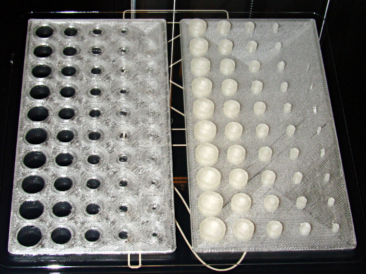
Of course, they didn’t, but they came surprisingly close for a first attempt.
The 0.20 and 0.40 posts simply aren’t there, because they’re too small to print with a 0.35 mm diameter nozzle. The 0.60 through 1.40 mm posts were present, albeit fugly, and posts larger than that looked increasingly better.
Although all the holes were present, in the sense that you could see a disturbance in the top and bottom infill pattern, the first visibly open hole appeared at the 0.80 mm spot… and it was immeasurably small. Some holes had misplaced perimeter strands stretching across the openings, which is probably due to excessive speed from my fiddling around with the numbers.
Measuring them with a digital caliper, with no effort at finding the best orientation, then slapping the data into a Libreoffice spreadsheet, produces an interesting graph:
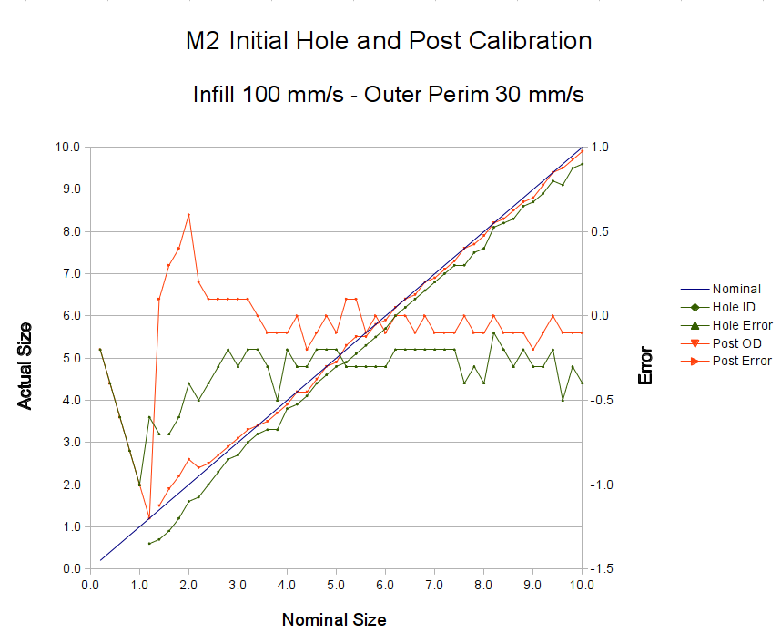
Above about 3 mm diameter: posts are 0.1 mm too small and holes are 0.3 mm too small. Around 2 mm, posts are too big and holes are way too small. What’s important: above maybe 2.5 mm, the error is essentially constant and does not scale with diameter, so a simple Finagle Constant (or two) can solve (most of) the problem.
Some experiments involving slic3r’s small-perimeter speed seem in order; it was 25 mm/s for these pieces.
More care in measurement would produce better answers, but the real question is whether you can produce holes and columns with known sizes; the answer (as expected) remains “with some care”. That’s not surprising; I expect to have an M2 + PLA version of the small hole diameter Finagle Constant that I’ve been using with Skeinforge + Thing-O-Matic; the correction will certainly fall in the same ballpark.
The slic3r configuration:
; generated by Slic3r 0.9.8 on 2013-04-01 at 16:20:49

; layer_height = 0.25
; perimeters = 1
; top_solid_layers = 3
; bottom_solid_layers = 3
; fill_density = 0.10
; perimeter_speed = 100
; infill_speed = 300
; travel_speed = 500
; scale = 1
; nozzle_diameter = 0.35
; filament_diameter = 1.70
; extrusion_multiplier = 0.9
; perimeters extrusion width = 0.40mm
; infill extrusion width = 0.40mm
; first layer extrusion width = 0.39mm
The source code comes from the Thingiverse customizer as bare G-Code, so there’s not much point in reproducing it here.

Comments
6 responses to “Makergear M2: Post and Hole Calibration Test Objects”
Just curious, what belt pulley/ pulley combo the M2 uses? The reason behind the question is related to how the entire STL to motion translation math occurs. For example, your T-O-M uses 17t GT2 2mm pitch pulleys AKA 34mm linear distance per rev. That then results in a non-even numbered steps per mm (1600/34=47.05882). On the U-T-O-M, I now use 20t GT2 2mm, making an even number of 40 steps per mm. Yes, technically I lost resolution, but did I gain in floating point math performance, especially if any of that happens in the 8 bit microcontroller? You are using different firmware and software but I’m curious on your opinion as to what is the right answer? Is it increasing physical resolution to an even number? Is there some magic number that makes more sense over another? Does it matter at all? Obviously, we run into constraints based on shaft diameter and what is available in standard pulleys and belts.
The M2 uses the same 2 mm belts with 18 tooth drive pulleys, so the 1/16 microstep motors run at 88.89 step/mm: obviously, not a nice round number.
Probably not, within reasonable limits. I think motor torque limits will kick in with larger pulleys, so there’s a strong incentive to keep ’em small.
The G-Code specifies floating-point distances that eventually get converted to steps, but Dan tells me there’s a truncation/roundoff accumulator holding fractional steps to ensure they don’t get lost: each motion must cover an integral number of (micro)steps, but any remaining fraction gets included in the next motion calculation. As a result, every endpoint will be within half a (micro)step of its correct position, about 0.01/2 mm for the M2, with no accumulating error. At least, I think that’s true for contemporary 3D printer motion planners.
It matters much more on the Z axis, where people are using crazy-thin layers. The M2 has 400 step/mm on the Z axis, which means each (micro)step should move the stage 0.0025 mm. If you want 0.020 mm layers, then you have only 8 (micro)steps between each one. Whereupon, we commence discussing the accuracy of each (micro)step position vs. mechanical backlash vs. stiction vs. whatever; I’m not going there. [grin]
Also, I’m probably incorrect in that the 20t gave me better floating point math, obviously, we don’t end up with even numbers on the STL side of it.
And the microprocessors don’t really care how nice the decimal representation of a number is. For basic arithmetic, they churn the same amount for 2.0 as they do for 1.23456789123. Even things such as square root, when “correctly” implemented for a uprocessor takes the same number of cycles for all inputs unless someone front-ended it with some test (e.g., input is zero, input is 1, etc.).
[…] my OpenSCAD module based on nophead’s polyholes to adjust low-vertex polygons by a constant +0.2 mm produces results that are within ±0.1 mm of the nominal value for holes larger than 3.0 […]
[…] At this diameter and number of faces, the M2 produces almost perfectly accurate dimensions, so the bullets press-fit in place just like you’d expect. […]