The CNC version of the corner clips looks much better than the prototypes:

Tightening the screws until the clip just flattens puts enough force on the glass + heat spreader stack to hold it firmly against the balls in the bottom pad. The solid rubber L-shaped bumpers and screws hold the glass in position against XY forces… and the whole affair looks much better than the original (and perfectly serviceable) bulldog clips. These clips free up the entire surface of the glass plate, minus four 12 mm triangles that you could, if you were desperate, print right over.
Although it’d be easier to just hack out an angular clip, I wrote a bit of G-Code to put a nice radius on each corner. The clip sits atop the rubber bumper with a 0.5 mm margin to keep the metal edges away from fingers; they’re smooth, but it’s still a strip of 6 mil (= 0.15 mm) phosphor bronze and feels a lot like a knife edge if you press hard enough.
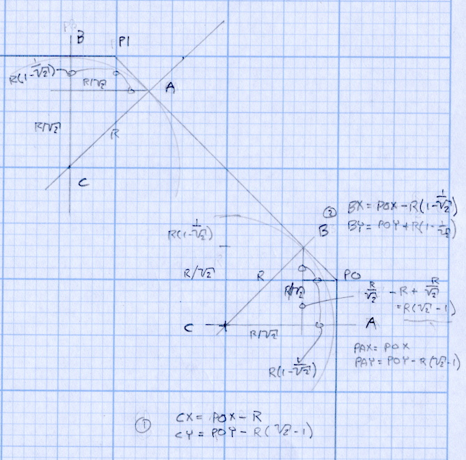
The radius on the three outside corners is a special-case solution of the general circle-through-three-points problem, taking advantage of the symmetry and right-triangle-ness of the corners. This sketch shows the details:

The two corners on the bevel over the glass plate have a fixed radius. I reworked my original fairing arc solution for outside cutting and doodled it up for this situation:
The outside corner radius worked out to 5 mm and I set the bevel radius at 3 mm. I think the latter made those corners a bit too sharp, but it’s Good Enough for my simple needs.
Drilling and machining the clips required a fixture:

That’s a story for another day.
I used cutter diameter compensation to mill the edges, starting oversize by 1.5 mm and working downward by 0.5 mm on each pass to the actual diameter. That gradually trimmed off the edges without any excitement, so I could start with rough-trimmed stock and not worry about precision hand trimming.
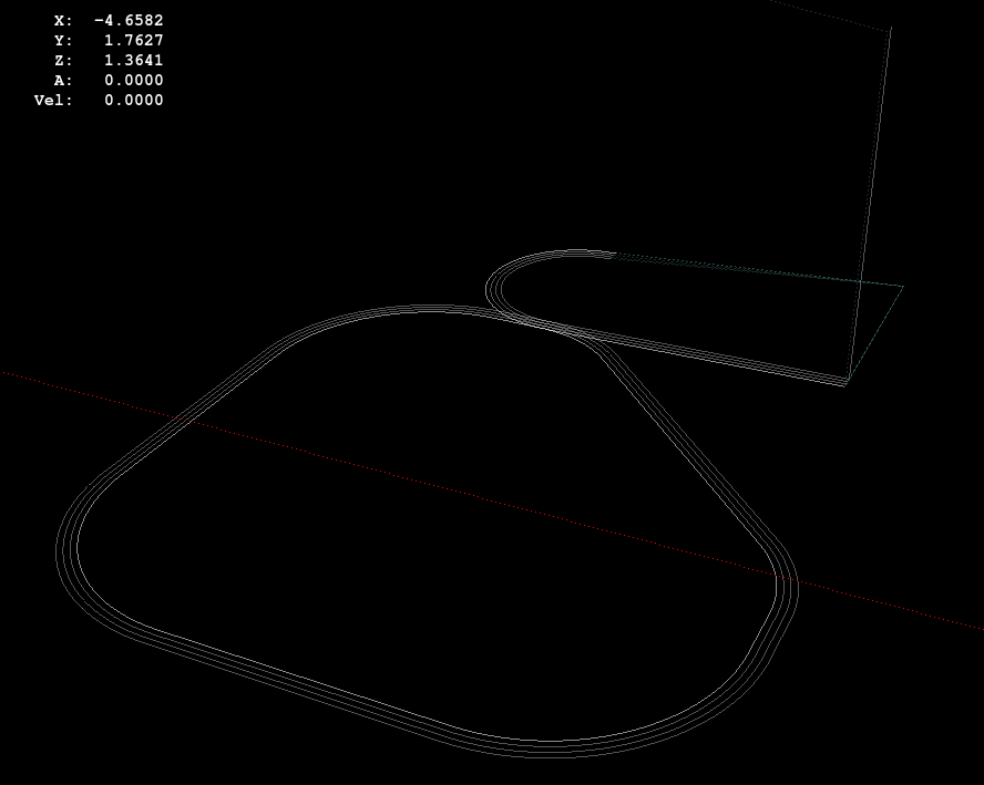
I thought climb milling (CW around the part) would produce better results, but it tended to smear the phosphor bronze against the fixture:

Conventional milling (CCW around the part) actually worked, but it required fancier entry and exit moves:
This part is the kind and size of machining perfectly suited to a Sherline CNC mill…
The LinuxCNC G-Code source:
( M2 Build Platform Corner Clips )
( Ed Nisley - KE4ZNU - July 2013 )
( Fixture origin at right-front corner pip )

( Flow Control )
#<_Do_Drill> = 0		( Drill two holes in clip )
#<_Do_Mill> = 1			( Mill clip outline )
#<_Climb_Mill> = 0		( 0 = conventional 1 = climb)

( Fixture info )
#<_Drill_X_Fixture> = 5.0	( Drill station origin )
#<_Drill_Y_Fixture> = 5.0

#<_Drill_Num> = 30			( Drill number in tool table)
#<_Drill_Retract> = 15
#<_Drill_Depth> = -1.0
#<_Drill_Feed> = 300
#<_Drill_Speed> = 3000

#<_Mill_X_Fixture> = 40.0	( Mill station origin )
#<_Mill_Y_Fixture> = 5.0

#<_Mill_Num> = 3			( Mill number in tool table)
#<_Mill_Dia> = 4.60			( actual tool diameter)
#<_Mill_Dia_Incr> = 0.50
#<_Mill_Dia_Steps> = 3
#<_Mill_Retract> = 15
#<_Mill_Depth> = -0.5
#<_Mill_Feed> = 300
#<_Mill_Speed> = 8000

(----------------)

(  Initialize first tool length at probe switch )
(     Assumes G59.3 is still in machine units, returns in G54 )
(  ** Must set these constants to match G20 / G21 condition! )

#<_Probe_Speed>     = 400            ( set for something sensible in mm or inch )
#<_Probe_Retract>   =   1            ( ditto )

O<Probe_Tool> SUB

G49                     ( clear tool length compensation )
G30                     ( move above probe switch )
G59.3                   ( coord system 9 )

G38.2 Z0 F#<_Probe_Speed>           ( trip switch on the way down )
G0 Z[#5063 + #<_Probe_Retract>]     ( back off the switch )
G38.2 Z0 F[#<_Probe_Speed> / 10]    ( trip switch slowly )

#<_ToolZ> = #5063                    ( save new tool length )

G43.1 Z[#<_ToolZ> - #<_ToolRefZ>]    ( set new length )

G54                     ( coord system 0 )
G30                     ( return to safe level )

O<Probe_Tool> ENDSUB

(-------------------)
(-- Initialize first tool length at probe switch )

O<Probe_Init> SUB

#<_ToolRefZ> = 0.0      ( set up for first call )

O<Probe_Tool> CALL

#<_ToolRefZ> = #5063    ( save trip point )

G43.1 Z0                ( tool entered at Z=0, so set it there )

O<Probe_Init> ENDSUB

(-------------------)
(-- Mill one pass around outline with tool diameter passed in #1 )

O<MillOutline> SUB

#<X_Size> = 22.0		( size of support spider pad = nominal clip size )
#<Y_Size> = 22.0
#<Base_Bevel> = 3.2		( X or Y length of corners clipped from spider pad )

#<Bevel_Size> = 9.0		( remaining part of trimmed edges on clip )
#<Bevel_Radius> = 3.0	( fairing radius at bevel corners on clip)

#<R_Div_Root2> = [#<Bevel_Radius> / SQRT[2]]
#<R_1M_Recip_R2> = [#<Bevel_Radius> * [1 - 1/SQRT[2]]]
#<R_Root2_M1> = [#<Bevel_Radius> * [SQRT[2] - 1]]

#<Margin> = 0.5			( recess inside of nominal )

#<X_Min> = [#<Margin>]
#<X_Max> = [#<X_Size> - #<Margin>]

#<Y_Min> = [#<Margin>]
#<Y_Max> = [#<Y_Size> - #<Margin>]

#<Corner_Rad> = [[#<Margin> * [1 - SQRT[2]] + [#<Base_Bevel> / SQRT[2]]] / [SQRT[2] - 1]]

O<Climb> IF [#<_Climb_Mill>]

G0 X#<X_Min> Y[#<Y_Max> + 3*#<_Mill_Dia>]
G1 Z#<_Mill_Depth> F#<_Mill_Feed>

G41.1 D#1

G3 X[#<X_Min>] Y#<Y_Max> I0 J[0-1.5*#<_Mill_Dia>]	( cutter comp on: entry move)

G1 X[#<Bevel_Size> - #<R_Root2_M1>]
G2 X[#<Bevel_Size> + #<R_1M_Recip_R2>] Y[#<Y_Max> - #<R_1M_Recip_R2>] J[0-#<Bevel_Radius>]

G1 X[#<X_Max> - #<R_1M_Recip_R2>] Y[#<Bevel_Size> + #<R_1M_Recip_R2>]
G2 X#<X_Max> Y[#<Bevel_Size> - #<R_Root2_M1>] I[0-#<R_Div_Root2>] J[0-#<R_Div_Root2>]

G1 Y[#<Y_Min> + #<Corner_Rad>]
G2 X[#<X_Max> - #<Corner_Rad>] Y#<Y_Min> I[0-#<Corner_Rad>] J0

G1 X[#<X_Min> + #<Corner_Rad>]
G2 X#<X_Min> Y[#<Y_Min> + #<Corner_Rad>] I0 J#<Corner_Rad>

G1 Y[#<Y_Max> - #<Corner_Rad>]
G2 X[#<X_Min> + #<Corner_Rad>] Y#<Y_Max> I#<Corner_Rad> J0

G40

G0 X#<X_Min> Y[#<Y_Max> + 3*#<_Mill_Dia>]
(G3 X#<Bevel_Size> Y[#<Y_Max> + 3*#<_Mill_Dia>] I0 J[1.5*#<_Mill_Dia>])	( cutter comp off: safe exit)

G0 X#<X_Min>			( return to start)

O<Climb> ELSE

G0 X#<X_Size> Y[#<Y_Size> + #1/2]

G1 Z#<_Mill_Depth> F#<_Mill_Feed>

G42.1 D#1

G1 X#<Bevel_Size> Y[#<Y_Max>]	( cutter comp on: entry move)

G1 X[#<X_Min> + #<Corner_Rad>]
G3 X#<X_Min> Y[#<Y_Max> - #<Corner_Rad>] I0 J[0-#<Corner_Rad>]

G1 Y[#<Y_Min> + #<Corner_Rad>]
G3 X[#<X_Min> + #<Corner_Rad>] Y[#<Y_Min>] I#<Corner_Rad> J0

G1 X[#<X_Max> - #<Corner_Rad>]
G3 X[#<X_Max>] Y[#<Y_Min> + #<Corner_Rad>] I0 J#<Corner_Rad>

G1 Y[#<Bevel_Size> - #<R_Root2_M1>]
G3 X[#<X_Max> - #<R_1M_Recip_R2>] Y[#<Bevel_Size> + #<R_1M_Recip_R2>] I[-#<Bevel_Radius>]

G1 X[#<Bevel_Size> + #<R_1M_Recip_R2>] Y[#<Y_Max> - #<R_1M_Recip_R2>]
G3 X[#<Bevel_Size> - #<R_Root2_M1>] Y#<Y_Max> I[-#<R_Div_Root2>] J[-#<R_Div_Root2>]

G2 Y[#<Y_Max> + 3*#<_Mill_Dia>] J[#<_Mill_Dia>*1.5]		( get away from corner)
G40

G0 X#<X_Size>					( cutter comp off: safe exit)
G0 Y[#<Y_Size> + #1/2]			( return to start)

O<Climb> ENDIF

O<MillOutline> ENDSUB

(----------------)
( Start machining... )

G17 G40 G49 G54 G80 G90 G94 G99	( reset many things )

G21								( metric! )
G91.1 							( incremental arc centers)

(msg,Verify: G30.1 position in G54 above tool change switch? )
M0
(msg,Verify: fixture origin XY touched off? )
M0
(msg,Verify: Current tool Z=0 touched off? )
M0

( Set up probing)
O<Probe_Init> CALL
T0 M6

(---- Drill holes)

O<DoDrill> IF [#<_Do_Drill>]

(debug,Insert drill tool = #<_Drill_Num>)
T#<_Drill_Num> M6
O<Probe_Tool> CALL
(debug,Set spindle to #<_Drill_Speed> rpm )
M0

G0 X#<_Drill_X_Fixture> Y#<_Drill_Y_Fixture>
G0 Z#<_Drill_Retract>

G10 L20 P2 X0 Y0 Z#<_Drill_Retract>	( P2 = G55)
G55					( drill station coordinates )

G81 X5.0 Y15.0 Z#<_Drill_Depth> R#<_Drill_Retract> F#<_Drill_Feed>

G81 X15.0 Y5.0

G54

O<DoDrill> ENDIF

(---- Mill outline )
( Start with large diameter and end with actual diameter to trim in stages)

O<DoMill> IF [#<_Do_Mill>]

(debug,Insert mill tool = #<_Mill_Num>)
T#<_Mill_Num> M6
O<Probe_Tool> CALL
(debug,Set spindle to #<_Mill_Speed> rpm )
M0

G0 X#<_Mill_X_Fixture> Y#<_Mill_Y_Fixture>
G0 Z#<_Mill_Retract>

G10 L20 P2 X0 Y0 Z#<_Mill_Retract>	( P2 = G55)
G55					( mill station coordinates )

#<PassCount> = 0

O<MillLoop> DO
#<Diameter> = [#<_Mill_Dia> + [#<_Mill_Dia_Steps> - #<PassCount>]*#<_Mill_Dia_Incr>]

O<MillOutline> CALL [#<Diameter>]

#<PassCount> = [#<PassCount> + 1]
O<MillLoop> WHILE [#<PassCount> LE #<_Mill_Dia_Steps>]

( Finishing pass with zero cut )
O<MillOutline> CALL [#<Diameter>]

G0 Z#<_Mill_Retract>
G54

O<DoMill> ENDIF

G30

(msg,Done!)
M2
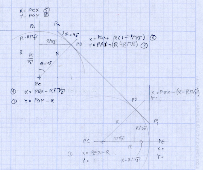
The rest of the doodles, which don’t match up with the final G-Code because they represent the earliest versions of the layout:


Comments
9 responses to “Makergear M2: CNC Platform Corner Clips”
Looks like good idea. Also seems feasible to print in ABS.
The corners will be the coolest spots on the platform and ABS would probably be OK at PLA platform temperatures. I’ll eventually start running ABS through the M2, as some of the things I print must withstand more than room temperature, and then it might get iffy.
As with most things, it probably wouldn’t matter, though…
Can you send drawing? If so, I’ll print a set in ABS & give ’em a try. Any format that can be read by Autodesk Inventor or Sketchup.
The only “drawing” would be those sketches: the G-Code comes out of my fingertips. Crude, but effective… at least for trivially simple shapes like those things.
Here’s a high-contrast scanned image of two clips at 640 dpi:
I think you can get from that to a DXF with some image-processing fu… easier than drawing one, at least for me. [grin]
When I saw the first picture, I wondered how, exactly, you could mill thin material like that. I learned something today. Thanks!
Real Machinists probably use laser cutters for this sort of thing nowadays, but the good old stack-em-and-whack-em approach still works…
A semi-random thought. I don’t know if the heater will cause any problems with the foam rubber, but if it does, you can get silicone rubber foam. We used this (in various thicknesses) with our Temptronic Thermostream mini-chamber for characterizing ICs under development. They offered foam kits, but I suspect the prices would be far better from the usual eBay suspects. I know it was available down to 1/4″, and possibly 1/8″. (Or the metric near-misses.) The quick summaries say the foam is good to 260 C, so if the mouse pad is a problem, you wouldn’t have to do something ugly with red RTV. NTTAWWT [grin]
Running the platform at 70 C hasn’t released The Big Stink, but I’ll definitely keep that in mind when I use ABS: having the corners get all melty should remind me!
[…] Makergear M2: CNC Platform Corner Clips Water Heater Thermophile […]