Having scouted out the territory inside the KeyboardIO Atreus, adding an LED requires taking it completely apart to drill a hole in the aluminum faceplate:
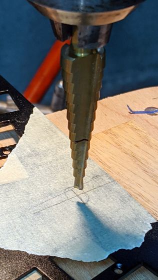
Reattaching the plate to the PCB with only three screws allows marking the hole position on the PCB, which is much easier than pretending to derive the position from first principles:

Despite appearances, I traced the hole with a mechanical pencil: black graphite turns shiny silvery gray against matte black soldermask. Also, the PCB trace is off-center, not the hole.
Overlay the neighborhood with Kapton tape to protect the PCB from what comes next:
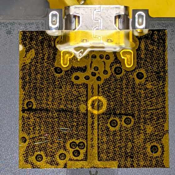
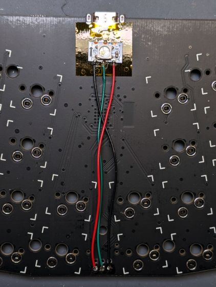
Snip a WS2812 RGB LED from a strip, stick it in place with eyeballometric alignment over the target, and wire it up:
Despite the terrible reliability of WS2812 RGB LEDs mounted on PCB carriers, a different set on a meter of high-density flex tape have worked reasonably well when not thermally stressed, so I’ll assume this one arrived in good order.
Aligning the LED directly under the hole required a few iterations:
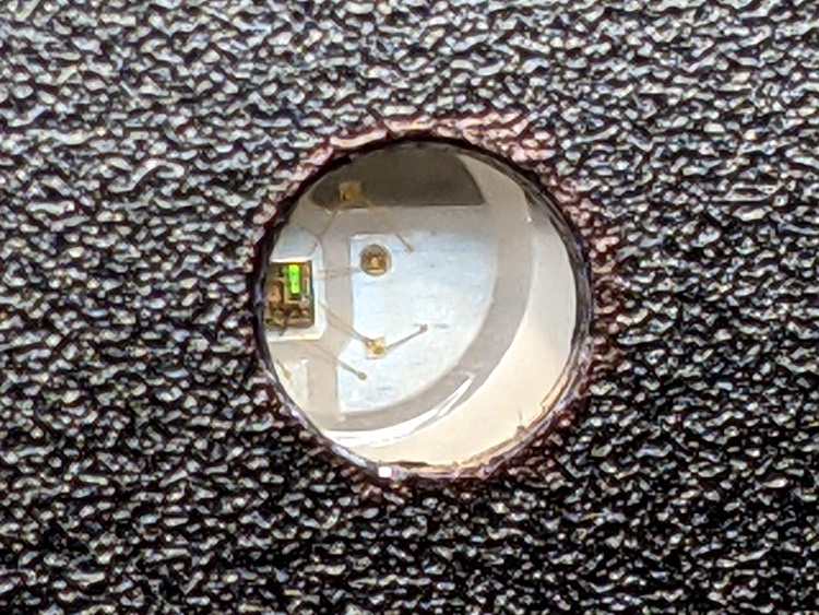
The iridescent green patch is a diffraction pattern from the controller chip’s internal circuitry.
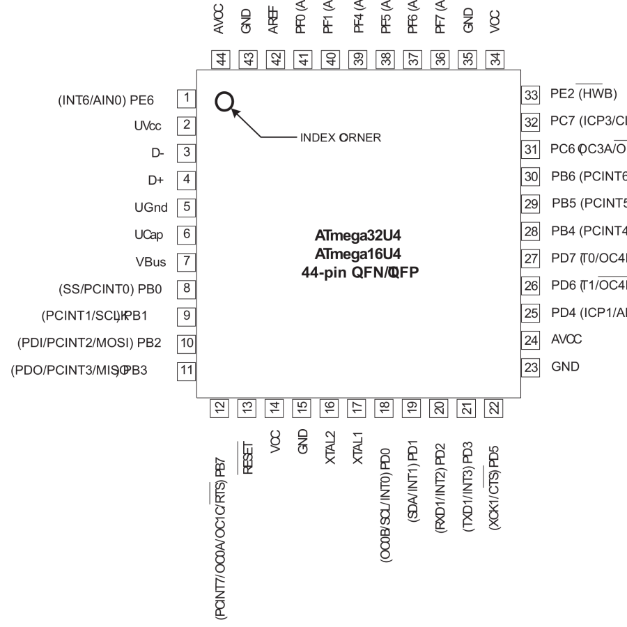
The data comes from MOSI, otherwise known as B2, down in the lower left corner:
Actually lighting the LED now becomes a simple matter of software QMK firmware.

Comments
One response to “KeyboardIO Atreus: RGB LED Installation”
[…] wired a WS2812 RGB LED into my KeyboardIO Atreus, lighting it up requires some QMK firmware configuration. It’s […]