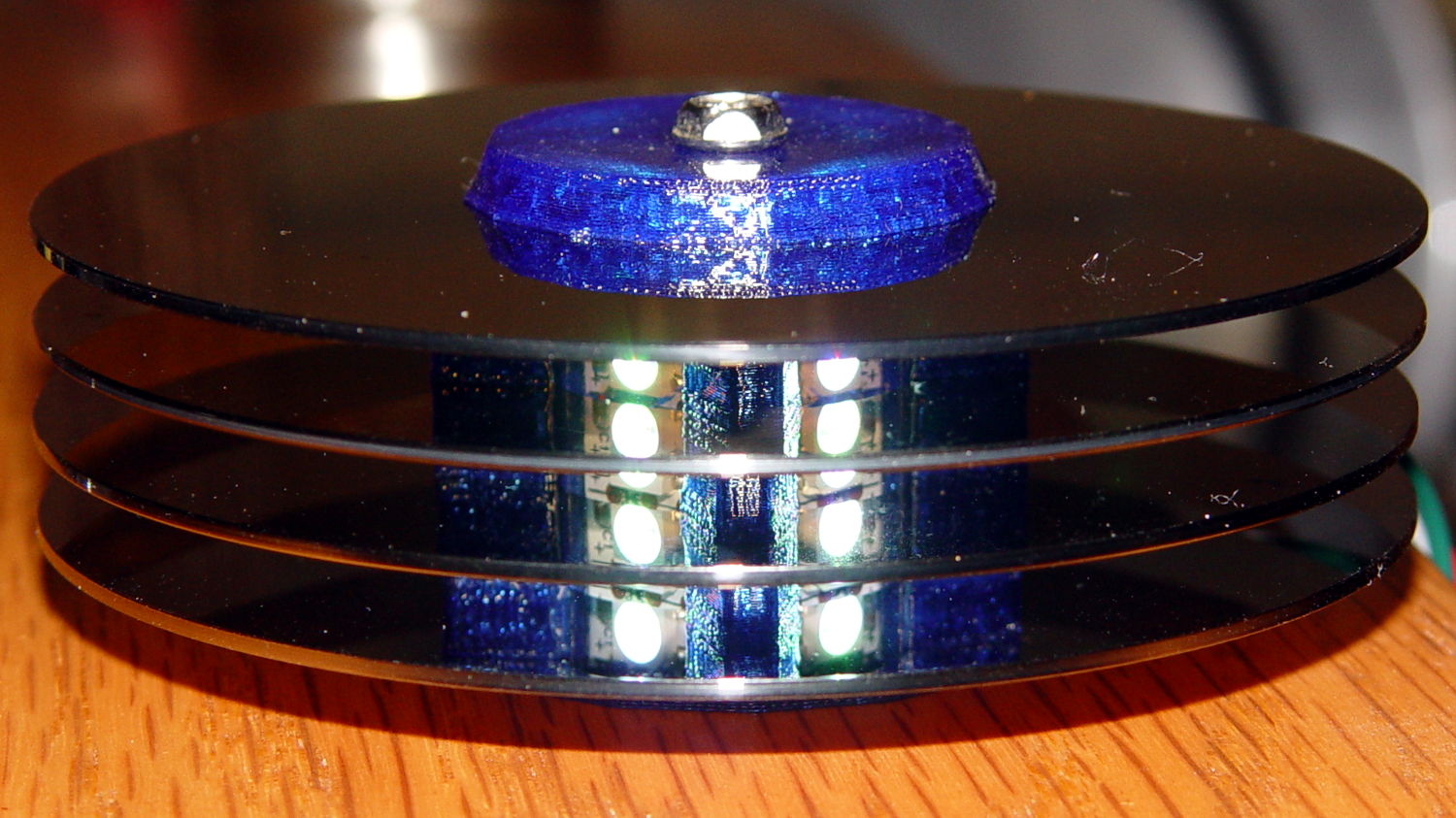
About a week after First Light, one of the knockoff Neopixels (not a Genuine Adafruit Product) suffered an intermittent failure: it worked fine after being off for an hour or two, but eventually stalled at a fixed color, with all downstream pixels equally dead. Of course, it was the middle package in the string of three, buried in the hub (this is before the failure):
Spraying circuit cooler on the package brought it back to life for a few minutes, confirming the diagnosis. Reducing the maximum intensity to PWM 32 reduced the average power dissipation enough to let it run for as long as I was willing to let it, although it might not survive a hot summer day.
Not having glued the spacers onto the hub simplified extracting the strip, although warranty repair is always a nuisance. I daubed red Sharpie on the failing LED to avoid losing track of it, then resoldered the LED and capacitor connections to no avail:
There’s nothing obviously wrong inside:
The fine details of the WS2812B controller produce a horrible Moiré blur with the camera’s low-res image, but you get the general idea.
Most likely, one of those flying wires isn’t quite bonded, but we’ll never know…

Comments
16 responses to “Neopixel Knockoff: Early Failure”
I could try taking a photomicrograph of it (microscope + adapter + camera) but I doubt even a clear picture would show what’s wrong.
I wonder what the apparently unbonded pads are for…
Test points, programming nodes, or an optional feature. In a chip like this, it could be used to trim/program the output current before packaging. [test engineer hat off]
Heat sensitive failures have way too many possibilities. An old one is wire bonding–in the ’60s-early 70s, “purple plague” was a problem with a couple of failure-inducing gold-aluminum compounds forming where you should have a gold-aluminum weld. Better process control solved that, but I saw a few (literally, less than 5) cases over the years. [On the gripping hand, it could be making a comeback with the Usual Sources.]
On the chip level, you could have problems between interconnect layers (vias not working correctly, or a couple layers almost shorting due to a defect. I did failure analysis (a very dark art) on our analog process chips, and 1 micron defects could kill a chip made on a 5 micron (minimum geometry) process. Modern processes use geometries smaller than optical methods can even resolve.
DFT Engineer, here. Yep, things are really small. Our next design is 16nm. At that point there are roughly 30 silicon atoms across the smallest feature. Intel is apparently working on 5nm at which point continued miniaturization basically grinds to a halt. Since my profession is highly related to the idiosyncrasies of the silicon manufacturing process, I am pretty damn curious about what happens next.
I definitely need a better camera for the microscope! By eye, the pad-like features look more like circuit elements than test points or fuses.
Note that there may be no difference between a test and a bonding pad, except that the former isn’t hooked up in the package. In the stone ages, we’d do smaller pads for test points, but that wasn’t ideal. If you had the space, you tried to use a full sized pad.
Not sure of this technology, but in the (bipolar) processes I dealt with, the pad had no circuitry in it, with all the goodies a ways away (25 microns by our design rules). You could program with fuses or zappable diodes, and the fuses were either NiCr or (as I heard) silicon. National ICs used a lot of zener zapping. I’d guess that Linear Tech might still do so. In bipolar, you might find a Schottky diode that looks something like a pad. Ours were the same size as pads in the PROMs.
On a part like this, I suppose you could have a pad to some flash memory to handle programming. By not bonding it to the outside world, the progamming’s not going to be changed.
Possibly test points. This picture of a similar LED driver chip shows dents left by probes on pads without bond wires. http://bunniestudios.com/blog/images/ntw_feb_2013_ic.jpg
With that as a guide, the eyeballometric survey says they didn’t do any probing / programming on these chips: all the padlike things without wires are dead flat and unscarred.
Of course, these being the knockoff variant, there may be zero margin for testing & fine tuning: if the LEDs light after wire bonding, ship it!
The LED pilot light on our Mr. Coffee died after 3 days of use. That machine replaced an identical one that died after 6 weeks from a heater failure. We took the hint and changed brands to a higher end Kitchenaid. Never realized how much I counted on that pilot light… Oh well, it’s a backup machine now.
Once is happenstance, twice is coincidence, but three times …
I suppose it’s possible the data out driver on the previous one failed.
I tried squirting cooler on that one, while shielding the one in the middle, and resoldered the data line, all to no avail. That could be yet another instance of my being both absolutely certain and dead wrong…
You’ll know for sure when you cut the bad one and test it directly… unless it magically heals itself in the process and becomes my favorite bug: non-reproducible
[…] another knockoff Neopixel started flickering and its blue LED went […]
[…] that knockoff Neopixel fail from overheating prompted me to measure what was going on. Because the LEDs sink most of their heat into the […]
[…] like a permanent WS2812B controller failure this time […]