Here’s what the 0.35 mm diameter nozzle of my Makergear M2 looks like when printing a 0.40×0.25 mm thread on borosilicate glass with a coating of hairspray:
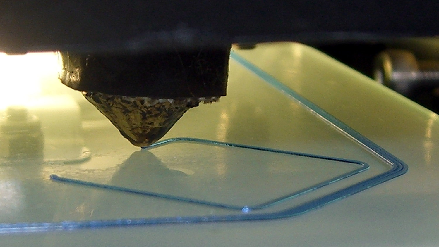
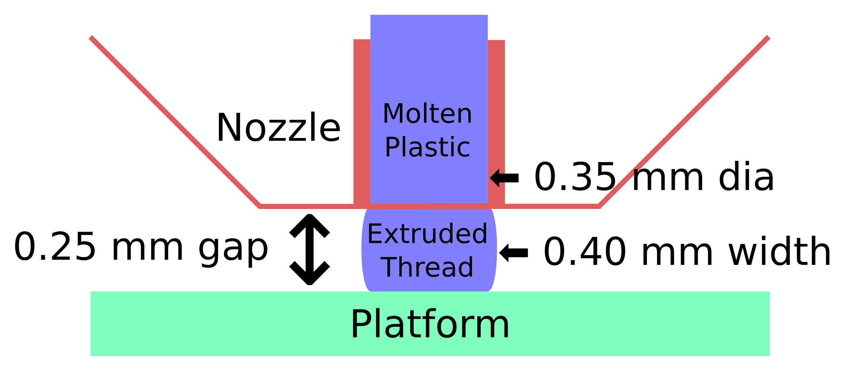
The dimensions:
Some common household objects at the same scale:
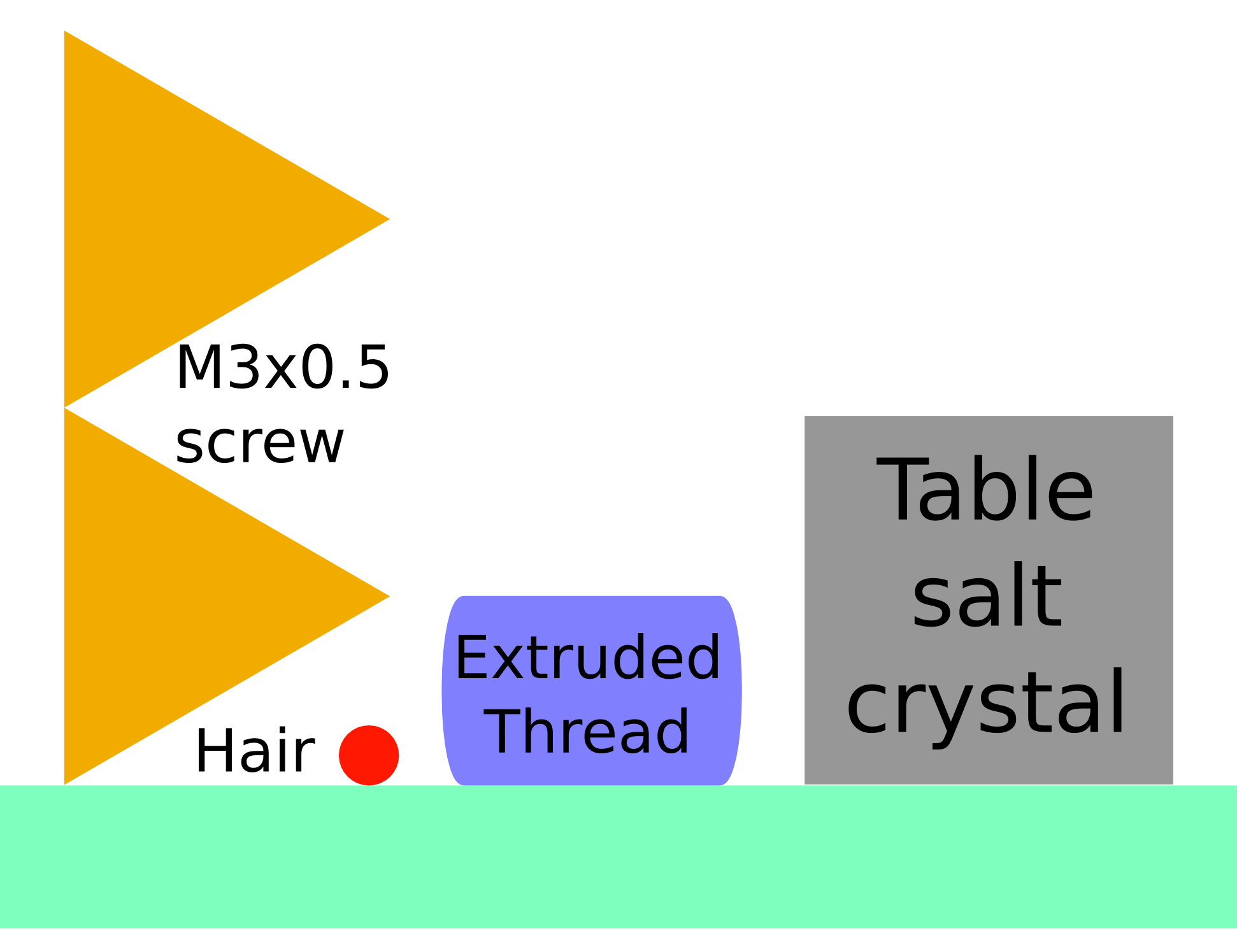
The accuracy required is literally hair-fine: being off by the diameter of the hair on your head can wreck the first layer of the printed object.
One turn of the M3 screws supporting the M2 platform move the mounting point by twice the thread thickness. Their positions on the platform amplify the motion by about a factor of two, so if you’re tweaking the screws by more than 1/6 turn at a time, you’re overdoing it.
For first-layer nozzle-to-platform distance adjustment:
- If it increases by 0.25 mm, the plastic won’t touch the platform
- If it decreases by 0.25 mm, the plastic won’t come out of the nozzle
For platform alignment:
- If your printer can’t maintain the proper gap to within ±0.10 mm across the entire platform, it won’t produce accurate results
- Platform alignment that looks good probably isn’t
After you do a coarse alignment and set the Extrusion Multiplier to get accurate thread width, print thinwall hollow boxes and use your trusty digital calipers to make the platform settings & adjustments perfect.
Works for me, anyhow. All I do is slice whatever object I’ve just designed, turn the M2 on, and print it. No muss, no fuss, no wasted motion: It Just Works.
The sketches come from my Digital Machinist column (DM 10.4). They’ve been covering a bunch of 3D printing topics, so if you’re interested in that kind of stuff…

Comments
One response to “3D Printer Nozzle-to-Platform Gap Visualization”
I always find it immensely useful to get a full perspective on any particular problem–understanding how small or large changes in settings have an effect on your outcome. I can see someone with their new 3D printer struggling with properly configuring it not knowing the dramatic changes they’re making with a single turn of the screw. I love that your post clearly demonstrates this.
This reminds me of the first time I tried flying a two-line stunt kite. I assembled it. Then started to tie the three-point harness together. And you probably see where this is going already… So there are six short lines connecting the kite to the two control lines to the operator. I’d get the kite to fly for 2 or 3 seconds and it would plummet. The changes I was making to the bridle were on the scale of an inch or two at a time.
Luckily I’m a patient guy and kept at it until I chanced upon a configuration that was Close Enough. Then I made one more (unknowingly gross) change to try and dial it in only to promptly fail again. At that point I started making tenth of an inch changes and quickly found the sweet spots for the bridle config.
A mention of that aspect in the instructions that came with the kite would have been incredibly helpful.