It turns out that attaching some, but not all, of the PCs around here to the Arduino Pro board controlling the Totally Featureless Clock cause the WWVB receiver to drown in a sea of noise. In fact, just touching the USB cable’s shield to the FTDI Basic USB-to-serial adapter would bring the noise.
So this is a quick-and-dirty circuit to see if optical isolation will reduce the problem enough to be bearable.
The schematic is pretty simple: two bits in, two bits out.

The layout puts the DIP isolators on the top and the SMD resistors on the bottom. I used fancy screw-machine IC socket pins, just because I had some, but you could solder the isolators directly to the board. The FTDI Basic connects through header pins and the Arduino connects through female header sockets, both soldered sideways to the top of the board. I’ll eventually reinforce them with some epoxy, never fear.
Double-size PCB layout:

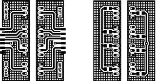
Actual-size copper images. Remember that the top copper is flipped left-to-right here so it comes out properly after toner-transfer imaging.

And the placement info showing where the parts wind up. This is sort of the silkscreen for the top and bottom, both together: the backwards stuff goes on the bottom side.

The alert reader will note that the photo doesn’t match the rest of the images. Nay, verily, eagle-eyed readers will have picked out a few resistors on the top and two embarrassing little red-wire Xes at the connectors. Somehow, I managed to swap the RxD and TxD pins, even with an FTDI board on the desk next to me. I hate it when that happens… so I fixed the schematic & layout for the next time around.
The resistors push a lot of current through the LEDs and phototransistors, which is what you need to get decent 19200 b/s serial data pulses. Here’s what the data stream out of the TxD isolator looks like:

I have the Eagle files and the CNC drill file for my Sherline mill if you must have them, but you can go from those images above directly to the hardware. It’s an evening’s work, more or less.
You might want to kludge a jumper into the Reset line so it’s impossible to accidentally reset the Arduino. Sometimes you don’t want a reset, like after a few days of data collection…
Now, does it actually do what I expected? The early reports are good, but I’m at the mercy of the atmosphere and must collect a few days (actually, nights) worth of data to find just how far down the noise went.

Regarding your PCB’s. Is the GRID pattern ground plane(Or just grid fill pattern) better than a solid copper fill in your opinion?
Well, it’s certainly prettier…
I use it because I wind up tacking things to the ground plane and it’s a whole lot easier to solder to a grid than an actual plane. You’ll notice a bunch of Z wires stitching the top & bottom pieces of the plane together; they’re just copper hookup wire poked through vias, bent over on both ends, and soldered to the plane.
As nearly as I can tell, there’s no electrical difference for most circuits as long as you keep the grid lines reasonably fat (equivalently, the “holes” reasonably small). Having a solid ground plane really, really matters for microwave circuitry, but I don’t go there.
Disadvantage: I must remove a bit more copper than with a solid plane.
Advantage: I know when to stop etching: as soon as the grid clears up, I’m done.
Nice points about the grid during etching. I didn’t think about it that way… I may need to start doing that. I also now use the Cool-Amp powder. That stuff is great.
That silver plating makes the boards much more photogenic, although the older ones in my heap look a bit, um, tarnished. Who’d’a thunk it?
My of very first jobs out of high school (long ago) was operating a wave solder machine so I got to see professional gold finger and tin electroplating of the boards prior to soldering. As a result… I just cringe at bare copper PCB’s ever since. When my last bottle of the magic Kepro tinning liquid was finished… I was quite sad to say the least. The tarnishing did cross my mind… about how long does it take to be noticeably tarnished?
I don’t have a good number, but a board built in May 2008 has been kicking around on the back of the bench since then (after a few months of use) and it looks silvery with an overlay of that gray discoloration you get on silver-plated RF connectors. I suspect the crud starts immediately, takes a few months to get to the point where it’s visible, then stabilizes. The silver’s only a few microns thick, so there’s not much to get more than discolored, anyway.
Might be my grubby paws, though, plus flux fumes from my unclean soldering habits…
What optocoupler did you use, or will any generic one work?
Thank you!
It was randomly chosen from my heap, so I suspect nearly anything will work. The transition times will limit the speed to not much over 19.2 kb/s, but that’s good enough for my simple needs.
I suppose a logic-output isolator would give better results…
Much appreciated :)