Given the overall slovenliness of the recently kludged tool length probe switch on my Sherline CNC mill, you have to have to ask yourself… does that thing actually work?
This boils down to a simple test: repeatedly poke the switch and record the Z-axis trip point. If it’s the same every time, then the switch is repeatable and life is good. If not, then the switch is moving: not good.
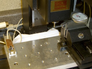
One good measurement being worth a thousand expert opinions, I devoted some Quality Shop Time to measuring the switch. The picture shows the simpleminded setup.
There’s a broken carbide cutter (I have a disturbing number of these) held in a collet, with its blunt end downward. The spindle isn’t turning, for obvious reasons.
The probe switch is as far in the -X direction as I can conveniently put it, screwed down to one of the T-nuts holding the tooling plate in place. The G30.1 tool change position is a few inches directly above the switch position.
The dial test indicator grabbed in the vise has 0.5 mil graduations, so it’s eyeballable to more-or-less 0.1 mil, although I have my doubts about the mechanical repeatability in that range. The arm is horizontal, with the XYZ origin set to the top of the ball.
The G-Code (shown below) probes the switch to establish & display the tool’s reference length. Actually, what we’re displaying is the Z-axis coordinate where the switch trips, then computing the new tool length from those values.
Then it does these steps 10 times:
- Go XY=0.0 Z=5, just above the indicator ball
- Go to Z=0.0. The indicator should read 0.0, too.
- Prompt me to write down the indicator reading
- G30 to the tool change location
- Probe the (unchanged) tool & display the new Z-axis value
So I did that and here’s the result. The second column is the indicator reading in mils, with negative numbers being further down toward the tooling plate. The third column is the Z-axis coordinate of the probe switch trip in mm.
| Iteration | Z @ Origin (mils) | Tool Z @ Probe (mm) |
| 0 | 0.0 | -50.008042 |
| 1 | 0.0 | -50.008873 |
| 2 | 0.0 | -50.010536 |
| 3 | 0.0 | -50.012032 |
| 4 | -0.1 | -50.013526 |
| 5 | 0.0 | -50.014193 |
| 6 | -0.2 | -50.014857 |
| 7 | -0.1 | -50.016686 |
| 8 | -0.1 | -50.016852 |
| 9 | -0.1 | -50.017185 |
| 10 | -0.1 | -50.018514 |
| Probe drift | -0.010472 |
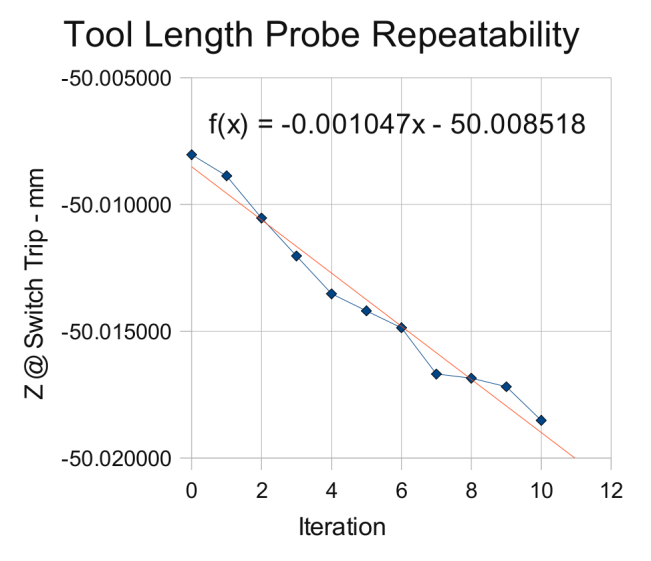
Now, that just cries out for a graph, doesn’t it?

The slope of the regression line says the switch is tripping about one wavelength of infrared light (1 micron) further down at each probe. Well, now, that’s not too bad, is it?
After ten probes, it’s descended about 10 microns, call it 0.3 mils, which is somewhat more than what the dial test indicator reports: 0.1 mil or just slightly more than the width of the indicator’s needle away from the 0.0 line.
It turns out that the switch doesn’t have any mechanical overtravel whatsoever, so when the switch contacts close, the button is already pretty much bottomed out.


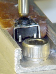
The left picture shows the tool a few millimeters over the switch. Notice that the top of the black plastic switch body is snug against the metal frame. Although you can’t see it here, there’s nothing but air below the body; the brown hot-melt glue secures the sides and submerges the terminals & wiring.
The right pictures shows the situation after probing the switch at 300 mm/min. The switch body is pushed slightly downward from the metal shell, showing that the Z axis drive didn’t screech to an instant halt after the switch tripped.
My back of the envelope said it’d stop in about 7 mils from 12 in/min (call it 0.2 mm from 300 mm/min, which is what I actually used here). Turns out it’s more like 15 mils, about 0.4 mm. So much for the back of the envelope…
On the other hand, what’s a binary order of magnitude among friends?
The routines below do an initial probe at 300 mm/min, back off about 1 mm, then probe again at 10 mm/min. The theory was that the switch overtravel would soak up the initial probe and the second, more gentle, probe would always trip at the same Z-axis level.
Another good theory all shot to hell…
I should do the initial probe at, say, 100 mm/min and (to speed things up) put the tool change location as close to the switch as the longest tool will allow. That should cut the overtravel down to 5 mils, which ought not be a real problem.
However, I think the switch is usable as-is. It’s certainly more accurate than my manual tool height adjustment and I really don’t do many jobs that require more than a few tool changes, separated by long periods of chewing away at the part.
I suspect the switch gradually oozes back to its original position after being rudely poked, but I ought to check that, too.
The G-Code to make the tests happen:
(Tool length probing test)

(--------------------)
( Initialize first tool length at probe switch)
( assumes metric units!)

O<Probe_Init> SUB

G49					( clear tool length compensation)
G30					( to probe switch)
G91					( relative mode for probing)

G38.2 Z-90 F300		( trip switch on the way down)

G0 Z1				( back off the switch)
G38.2 Z-10 F10		( trip switch slowly)

#<_ToolRefZ> = #5063	( save trip point)

G90					( absolute mode)
G30					( return to safe level)

O<Probe_Init> ENDSUB

(--------------------)
( Initialize new tool length at probe switch)
( assumes metric units!)

O<Probe_Tool> SUB

G49					( clear tool length compensation)
G30					( to probe switch)
G91					( relative mode for probing)

G38.2 Z-90 F300		( trip switch on the way down)

G0 Z1				( back off the switch)
G38.2 Z-10 F10		( trip switch slowly)

#<_ToolZ> = #5063				( save new tool length)

G43.1 K[#<_ToolZ> - #<_ToolRefZ>]	( set new length)

G90					( absolute mode)
G30					( return to safe level)

O<Probe_Tool> ENDSUB

(--------------------)
( Set up first tool)

G21					( metric units)

(msg,Verify origin at indicator ball, hit Resume)
M0
(msg,Verify G30.1 above tool change switch, hit Resume)
M0
(msg,Verify blunt tool installed, hit Resume)
M0

O<Probe_Init> CALL

(debug,Initial tool length = #<_ToolRefZ>)

O100 REPEAT [10]

G0 X0 Y0
G0 Z0
(msg,Record indicator Z-axis reading, hit Resume)
M0

G0 Z5				(get air)
G30					(to tool change position)

O<Probe_Tool> CALL
(debug,Tool length offset = #<_ToolZ>)

O100 ENDREPEAT

M2
And here you thought that switch was a total piece of crap, didn’t you?

You can get the full configured acceleration (and therefore half the overtravel) by switching to G61 mode for your probe moves.
The G38 doc says that that motion stops within the acceleration limits, so I’d expect the maximum configured acceleration anyway. Although G61 does ensure the path goes through the configured point, the switch will trip long before the Z axis arrives at the endpoint, so it’ll be decelerating from the programmed speed anyway.
Obviously I don’t get it… help me out! [sigh]
Hello,
I did something similar except for using the value to set it as tool length, I used it to set G55 Z offset.
But, with that approach, if I have a line such as “G55 G0 Z0.2”, linuxcnc gives me an error about “Program exceeds machine minimum on axis Z”
I assume that happened because linuxcnc has no way of knowing what the results of the G38.2 (probe) would be.
I am not sure if using the toollength instead of setting G55 is a better approach. Did you have the same issue/message?
Any thoughts, please?
Thanks
Joe
If I understand that correctly, you’re pinning the G55 coordinate system’s Z=0 level to the tool tip, which means the coordinates of the workpiece vary with every tool. The “exceeds machine minimum on axis Z” error means that you’ve tried to move below the machine’s lower Z axis limit, which is set by either the home switches or the initial defaults. I think that error comes for free with attaching the Z axis to the tool, because now the Z motions have nothing to do with the actual workpiece location or the underlying absolute machine coordinates: you can’t probe an unknown tool to a known location, because you can’t know that location without knowing the tool length.
The multiple coordinate system machinery was intended to be fixed to the workpieces / fixtures / whatever on the table, with the tool length offsetting the actual tool in the spindle relative to those coordinates. If your machine has toolholders that index to a known location in the spindle, you can pre-measure the tools offline, fill in the tool table, and run with it. My Sherline isn’t that fancy, so I measure each tool length on the fly, set the offset relative to a known tool, then run with the coordinate system aligned to the part.
I think happiness reaches a maximum when the LinuxCNC machinery is used as it was intended. It may be possible to contort the G-Codes and coordinates to work in a completely different way, but … nobody else will understand what you’re doing!