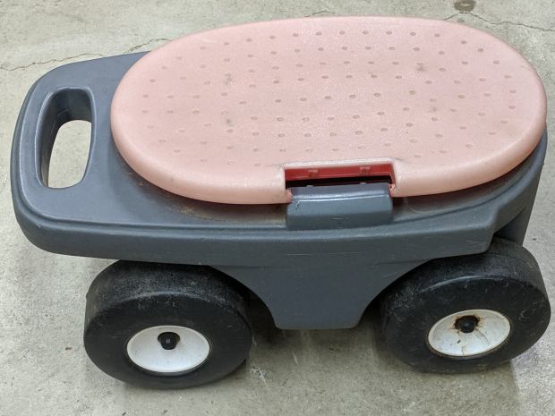
A pair of Step2 rolling garden seats (they have a new version) served in Mary’s gardens long enough to give their seat panels precarious cracks:
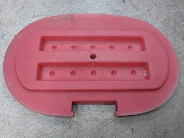
The underside was giving way, too:
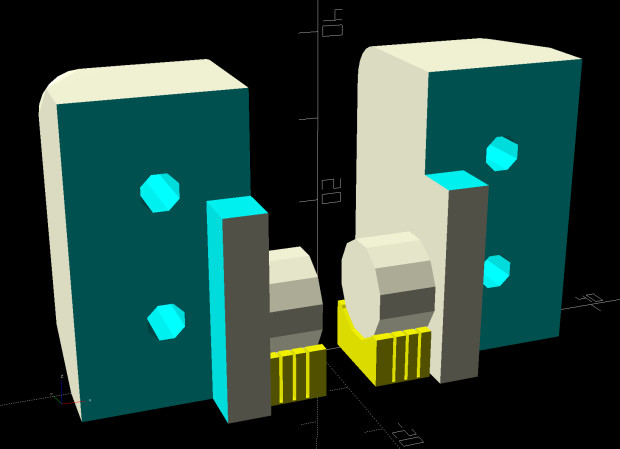
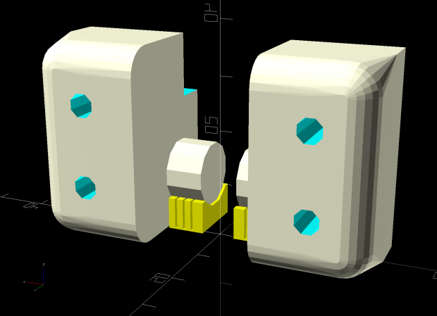
We agreed the new seat could be much simpler, although it must still hinge upward, so I conjured a pair of hinges from the vasty digital deep:
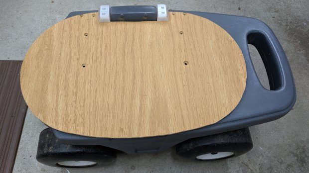
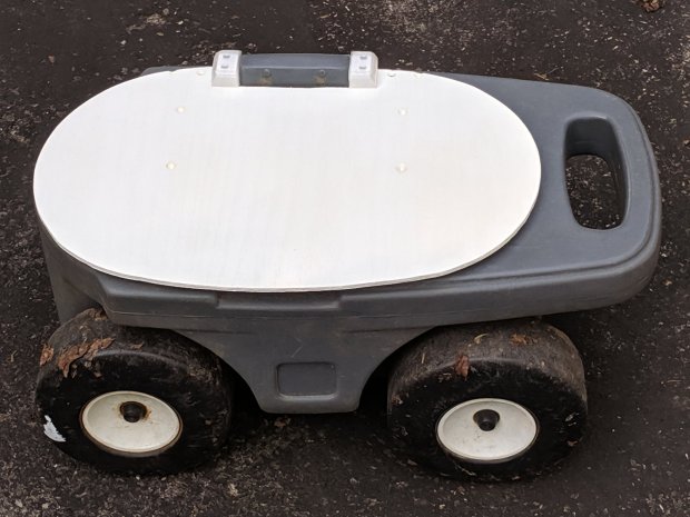
The woodpile disgorged a slab of 1/4 inch = 6 mm plywood (used in a defunct project) of just about the right size and we agreed a few holes wouldn’t be a problem for its projected ahem use case:
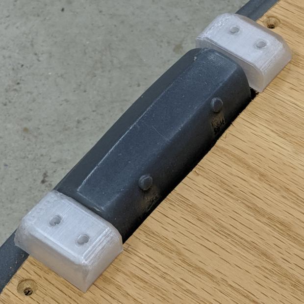
The screw holes on the hinge tops will let me run machine screws all the way through, should that be necessary. So far, a quartet of self-tapping sheet metal (!) screws are holding firm.
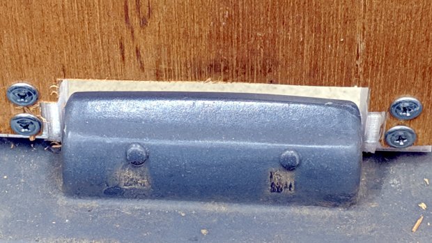
A closer look at the hinges in real life:
The solid model now caps the holes; I can drill them out should the need arise.
From the bottom:
Three coats of white exterior paint make it blindingly bright in the sun, although we expect a week or two in the garden will knock the shine right off:
After the first coat, I conjured a drying rack from a bamboo skewer, a cardboard flap, and some hot-melt glue:

Three small scars on the seat bottom were deemed acceptable.
The OpenSCAD source code as a GitHub Gist:
| // Hinge brackets for rolling garden stool | |
| // Ed Nisley - KE4ZNU - 2019-06 | |
| Layout = "Build"; // [Block,Build,Show] | |
| Support = true; | |
| /* [Hidden] */ | |
| ThreadThick = 0.20; | |
| ThreadWidth = 0.40; | |
| HoleWindage = 0.2; | |
| Protrusion = 0.1; // make holes end cleanly | |
| ID = 0; | |
| OD = 1; | |
| LENGTH = 2; | |
| //---------------------- | |
| // Dimensions | |
| SeatThick = 6.0; // seat panel above cart body | |
| HingePin = [11.5,12.0,7.0]; // ID = tip OD = base | |
| HingeOffset = 8.0; // hinge axis above cart body (larger than radius!) | |
| HingeBolster = [5.0,24.0,SeatThick]; // backing block below hinge | |
| Block = [25.0,HingeOffset + 30.0,23.0]; // Z = above cart body | |
| Screw = [3.8,11.0,2.5]; // self-tapping #8 OD=head LENGTH=head thickness | |
| ScrewOC = 15.0; // spacing > greater than head OD | |
| ScrewOffset = Block.y/2 - (ScrewOC/2 + Screw[OD]/2 + HingeOffset); // space for head behind hinge | |
| BlockRadius = 7.0; // corner rounding | |
| //---------------------- | |
| // Useful routines | |
| module PolyCyl(Dia,Height,ForceSides=0) { // based on nophead's polyholes | |
| Sides = (ForceSides != 0) ? ForceSides : (ceil(Dia) + 2); | |
| FixDia = Dia / cos(180/Sides); | |
| cylinder(r=(FixDia + HoleWindage)/2, | |
| h=Height, | |
| $fn=Sides); | |
| } | |
| // Basic block shape | |
| // X axis collinear with hinge axes, hinge base at X=0 | |
| module HingeBlock() { | |
| PinSides = 3*4; | |
| PinSupport = [HingePin[LENGTH] - 2*ThreadWidth,0.6*HingeOffset,HingePin[OD]]; // pre-rotated | |
| union() { | |
| translate([Protrusion,Block.y/2 - HingeOffset,HingeOffset]) | |
| rotate([0,-90,0]) | |
| rotate(180/PinSides) | |
| cylinder(d=HingePin[OD],h=HingePin[LENGTH] + Protrusion,$fn=PinSides); | |
| difference() { | |
| hull() { | |
| translate([Block.x - BlockRadius,-(Block.y/2 - BlockRadius),Block.z - BlockRadius]) | |
| rotate(180/PinSides) | |
| sphere(r=BlockRadius/cos(180/PinSides),$fn=PinSides); | |
| translate([0,-(Block.y/2 - BlockRadius),Block.z - BlockRadius]) | |
| rotate([0,90,0]) rotate(180/PinSides) | |
| cylinder(r=BlockRadius/cos(180/PinSides),h=Block.x/2,$fn=PinSides); | |
| translate([Block.x - BlockRadius,(Block.y/2 - BlockRadius),Block.z - BlockRadius]) | |
| sphere(r=BlockRadius/cos(180/PinSides),$fn=PinSides); | |
| translate([0,(Block.y/2 - BlockRadius),Block.z - BlockRadius]) | |
| rotate([0,90,0]) rotate(180/PinSides) | |
| cylinder(r=BlockRadius/cos(180/PinSides),h=Block.x/2,$fn=PinSides); | |
| translate([0,-Block.y/2,0]) | |
| cube([Block.x,Block.y - HingeOffset,Block.z/2],center=false); | |
| translate([0,Block.y/2 - HingeOffset,HingeOffset]) | |
| rotate([0,90,0]) rotate(180/PinSides) | |
| cylinder(r=HingeOffset/cos(180/PinSides),h=Block.x,$fn=PinSides); | |
| } | |
| translate([Block.x/2 + HingeBolster.x,0,(SeatThick - Protrusion)/2]) | |
| cube([Block.x,2*Block.y,SeatThick + Protrusion],center=true); | |
| translate([0,-HingeBolster.y,(SeatThick - Protrusion)/2]) | |
| cube([3*Block.x,Block.y,SeatThick + Protrusion],center=true); | |
| for (j=[-1,1]) | |
| translate([Block.x/2,j*ScrewOC/2 + ScrewOffset,-4*ThreadThick]) | |
| rotate(180/8) | |
| PolyCyl(Screw[ID],Block.z,8); | |
| } | |
| } | |
| if (Support) { // totally ad-hoc | |
| color("Yellow") render(convexity=4) | |
| difference() { | |
| translate([-(PinSupport.x/2 + 2*ThreadWidth),Block.y/2 - PinSupport.y/2,HingeOffset]) | |
| cube(PinSupport,center=true); | |
| translate([Protrusion,Block.y/2 - HingeOffset,HingeOffset]) | |
| rotate([0,-90,0]) | |
| rotate(180/PinSides) | |
| cylinder(d=HingePin[OD] + 2*ThreadThick,h=2*HingePin[LENGTH],$fn=PinSides); | |
| for (i=[-1:1]) | |
| translate([i*4*ThreadWidth - HingePin[LENGTH]/2, | |
| Block.y/2 - (PinSupport.y + 1*ThreadThick), | |
| HingeOffset]) | |
| cube([2*ThreadWidth,2*PinSupport.y,2*PinSupport.z],center=true); | |
| } | |
| } | |
| } | |
| module Blocks(Hand = "Left") { | |
| if (Hand == "Left") | |
| HingeBlock(); | |
| else | |
| mirror([1,0,0]) | |
| HingeBlock(); | |
| } | |
| //- Build it | |
| if (Layout == "Block") | |
| HingeBlock(); | |
| if (Layout == "Show") { | |
| translate([1.5*HingePin[LENGTH],0,0]) | |
| Blocks("Left"); | |
| translate([-1.5*HingePin[LENGTH],0,0]) | |
| Blocks("Right"); | |
| } | |
| if (Layout == "Build") { | |
| translate([0,-Block.z/2,Block.y/2]) | |
| rotate([-90,0,0]) { | |
| translate([1.5*HingePin[LENGTH],0,0]) | |
| Blocks("Left"); | |
| translate([-1.5*HingePin[LENGTH],0,0]) | |
| Blocks("Right"); | |
| } | |
| } |
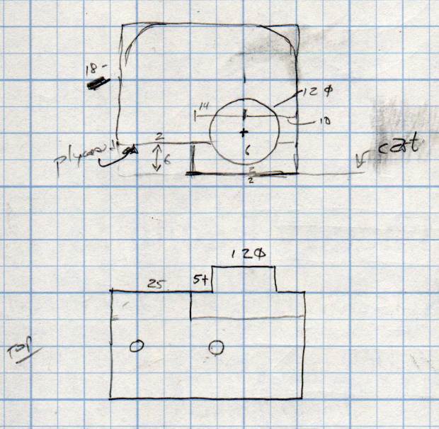
This original doodle gives the key dimensions, apart from the rounded rear edge required so the seat can pivot vertically upward:
The second seat looks just like this one, so life is good …

