Hall Effect Sensors From eBay: Variations On a Specification

It seems that the “49E” Hall effect sensor I used to measure the field in the ferrite toroid was running at 1.9 mV/G, rather than the 1.0 to 1.75 range suggested by the perhaps-not-quite-applicable specs. Here’s a table of all the sensors in my collection, which came in two bags from the usual eBay vendors:

Seq 49E 231NB AH49E
1 41.1 18.5
2 42.9 20.0
3 39.5 19.9
4 40.6 18.8
5 43.3 18.9
6 42.6 23.0
7 40.7 20.0
8 44.0 19.3
9 18.9
10 19.5
11 20.0
12 19.8

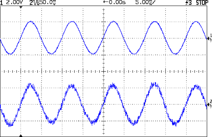
That’s the RMS value in mV of the sine wave resulting from a 200 mA peak current in the 25 turn winding, measured on the scope with low pass filtering and 8 trace averaging. An unfiltered and unaveraged trace looks like this, which explains why I’m knocking back the noise:

Hall Current Sense - 25T FT50-61 - raw
Hall Current Sense – 25T FT50-61 – raw

Even with that noise reduction, the variation between successive readings is about 5%, so trust only the first digit and half of the second; the fractional digit is worthless. Averaging the columns gives 42 and 20 mV RMS, which correspond to 59 and 28 mV peak. I estimated 60 mV peak from the filtered-but-not-averaged scope trace in the earlier calculations, which falls in the same ballpark. If you were doing this for real, you’d use a DC current and a static field, plus a simple RC filter to improve the noise rejection, but this was a quick-and-dirty measurement.

The peak magnetic flux should be about 31 to 33 G; I’ve been using 32 G based on the nominal permeability and measured air gap. Assuming that’s the case, then the sensors in the first column run at 1.8 mV/G (1.75 + 3% or 1.7 + 6%) and those in the second column at 0.875 mv/G (1.0 – 9%).

Here’s what I think: these are manufacturing rejects, sold cheap to extract money from suckers. Those in the first column came from the “too high” scrap heap, the second column’s contestants were in the “too low” pile. Note the tight clustering: they’re not random, they’ve been carefully selected! A quick-and-dirty histogram tells the tale:

49E Hall Effect Sensor Histogram - 200 mA 32 G
49E Hall Effect Sensor Histogram – 200 mA 32 G

The nominal range, taken from the SS49E datasheet, runs neatly across the gap in the middle, with one sensor falling just barely inside. The SS49 range neatly brackets the data on the left, but that’s not what those parts are supposed to be.

Now, I’ve often referred to eBay as my parts locker (at least for stuff I don’t have in the Basement Laboratory Warehouse Wing), but I know what to expect and am not in the least surprised at these numbers. If you or anyone you know buys parts from eBay in the expectation that they’re getting Good Stuff Cheap, then you should rethink that expectation.

I’d say that, to a very good first approximation, anything bought directly from halfway around the planet via eBay (or any source like it) will be, at best, counterfeit. For my purposes, I can measure and use most of it (assuming it actually works and ignoring minor issues like, oh, reliability and stability). In an actual product application, eBay is not the way to get your parts.

No surprise, right?

I wonder what the supply current might be? They’re supposed to run around 6 mA, max 10 mA…

Hall Effect Current Sensor: Magnetic Flux Calibration

With a wound ferrite toroid in hand, the next step involves measuring the magnetic field in the gap from a known winding current. I don’t have a calibrated magnetic sensor, so all this involves considerable guesswork and estimation.

A ULN3751Z power op amp converts an input signal voltage into winding current:

Ferrite Toroid Winding Test Driver

The 10 Ω sense resistor (5% tolerance, measured at 9.97 Ω on a typical 5% meter) sets the conversion at 100 mA/V, which should be good enough for a first pass. The ULN3751Z has 40 to 60 mA quiescent current and would cook at 1.2 W from ±12 V supplies, so I used ±5 V for this test. That’s not enough for a wide output range, but it’s OK now.

Given that I already have a breadboard with a Hall effect sensor on it, I hairballed the winding driver in an empty spot:

Ferrite toroid winding test driver - breadboard
Ferrite toroid winding test driver – breadboard

The green ring in the foreground surrounds the toroid, with the slot around the Hall effect sensor sticking up from the breadboard. The toroid cross-section is about the same size as the sensor and the field in the gap seems sufficiently uniform to make positioning completely non-critical. I should conjure up a mount of some sort, just to keep the toroid from flopping around, but that’s definitely in the nature of fine tuning.

Driving a 200 mA peak current into the winding produces a rather noisy result from the Hall sensor:

Hall Current Sense - 25T FT50-61 - raw
Hall Current Sense – 25T FT50-61 – raw

Applying the oscilloscope’s low pass filter cleans it up a bit:

Hall Current Sense - 25T FT50-61 - LP
Hall Current Sense – 25T FT50-61 – LP

The peak current is 200 mA, so the MMF = 200 mA x 25 turn = 5 A·t.

Assuming μ = 125 and a 0.172 cm gap, then the magnetic flux works out to:

(0.4 π · 125 · 5) / (3.02 + 125 · 0.172) = 7.21 · 5 = 32 G

The Hall effect sensor specs are, at best, hazy, but something like 1.0 to 1.7 mV/G appears on most of the datasheets, with a nominal 1.4 mV/G. The measured peak voltage from the Hall sensor is maybe 60 mV, which suggests a nominal B = 43 G with a range from 60 down to 35 G.

Ferrite toroid datasheets give permeability to three or four significant figures, but also admit that the actual value can differ by ±25% from the nominal. However, the air gap dominates the equation, so B varies from 30.8 to 32.8 G over that range of μ.

Assuming that B = 32 G, then the sensor is running just shy of 1.9 mV/G. Perhaps it didn’t quite pass final inspection; it’s not like I’m buying from an authorized distributor or anything.

Anyhow, the results seems close enough to suggest the ferrite toroid and the Hall effect sensor actually do pretty much what they’re supposed to do. I’d have no qualms about calibrating the sensor output from a known current and running with that number…

Hall Effect Current Sensor: Winding and Armoring the Toroid

Winding a slit ferrite toroid poses no challenge, so putting 25 turns of 26 AWG wire on it didn’t take long at all:

F50-61 toroid - 25 turns 26 AWG
F50-61 toroid – 25 turns 26 AWG

However, a ferrite toroid doesn’t take kindly to being dropped and I figured that a slit toroid would crack under a stern look, so I decided to wrap some armor around it. A small squeeze bottle offered a cap just slightly larger than the winding, so I used that slitting saw to cut off a suitable ring.  The first step was to grab it in the 3 jaw chuck and align its axis parallel to the spindle:

Aligning bottle cap in 3-jaw chuck

I wanted to cut off a slightly taller ring, but the clamping screw on the saw arbor just barely cleared the chuck for a 5 mm ring. I jogged around the chuck jaws to cut two slits in the cap that eventually joined near the back:

Slicing ring from bottle cap

That was about 1000 rpm, no coolant, and slow feed, but also a totally non-critical cut in plastic.

I put a snippet of foam rubber in the slot, put the ring on a Kapton-covered build platform from the Thing-O-Matic, filled it with hot-melt glue, gooshed the toroid in place, and waited for cooling. Trimming and cleaning out the slit produced a hideously ugly, but (I hope) much more durable assembly:

Slit ferrite toroid - with armor
Slit ferrite toroid – with armor

I’m reasonably sure I didn’t crack the ferrite while cleaning out the slit; that hot-melt glue is tenaciously gummy stuff!

Now, to find out whether it actually works…

Slitting a Ferrite Toroid

The object of the game: cut a slit into a ferrite toroid that will accommodate a Hall effect sensor. Those doodles showed that an FT50 (half-inch OD) toroid would be about right for the cheap AH49/EH49 Hall effect sensors on hand and those doodles shows that the permeability of the ferrite mix doesn’t make much difference. Not being quite sure how this would work out, I figured I’d start with the simplest possible setup and complexicate things until it worked…

A fold of cereal box cardboard cushioned the brittle ferrite in the Sherline’s clamp and the vacuum hose in the background collects airborne grit. I touched off X=Y=Z=0 with the wheel at the center of the toroid’s equator:

Slitting ferrite toroid - first pass
Slitting ferrite toroid – first pass

The first pass went swimmingly, with the diamond wheel far more concentric than I expected, using manual jogging along a 0.5 mm deep cut. The wheel is slightly over 0.5 mm thick, measured on the grit, and showed no sign of strain on a 1 mm deep cut at 100 mm/min, so I used manual CNC to run the wheel back and forth along the cut.

After clearing the slot, I moved the wheel upward to + 0.5 mm, repeated the passes with a 1.5 mm depth of cut, then did the same at -0.5 mm. The end result was a nice slot with parallel sides:

Slitting ferrite toroid - complete
Slitting ferrite toroid – complete

The actual gap measured 1.72 mm, not the 1.5 I wanted, which means the flux density will be lower than the previous calculations predict. Assuming the Z axis backlash compensation works as it should, then the kerf is 0.72 mm. Of course, that also assumes the arbor runs true and the wheel cuts symmetrically, neither of which I’d put (or, heck, have put) a lot of money behind. On the other paw, the sensors are 1.5 mm thick (just under the datasheet’s 1.6 mm spec), so +0.1 mm clearance on each side works a whole lot better for me than, say, -0.1 mm.

All in all, there was no excitement, no muss, no fuss, no chipping, no breakage:

FT50 ferrite toroid with slit

Talk about beginner’s luck!

Hall Effect Current Sensor: More Toroid Numbers

After rummaging in the collection, it turns out those calculations for the FT50-43 toroid aren’t relevant: I only have a few of them. It turns out that the actual material doesn’t affect the result nearly as much as you’d think, because the air gap for the Hall sensor controls the net permeability, so I’ll start sawing toroids that I have in abundance…

The J ferrite mix has much higher permeability, at the cost of a lower Curie point. An FT50A toroid is slightly thinner and taller than an FT50, but I have good assortment of FT50A-J toroids:

  • 0.50 inch OD = 1.27 cm
  • 0.312 inch ID = 0.793 cm
  • 0.250 inch height = 0.635 cm
  • 0.152 cm2 area
  • 0.558 cm3 volume
  • 3.68 cm mean path length
  • μ = 5000
  • 4300 saturation flux (G) at 10 Oe
  • AL = 2970 nH/turn2

For 1000 G flux in a 0.15 mm air gap:

1000 = (0.4 π · 5000 · NI) / (3.68 + 5000 · 0.15) = 8.34 · NI

So NI = 1000/8.34 = 120, essentially the same as NI = 122 for the FT50-43. Given that μ increased by nearly a factor of 6, that shows permeability doesn’t matter very much at all.

There’s a bag of F50-61 toroids that I assume are actually FT50-61:

  • 0.50 inch OD = 1.27 cm
  • 0.281 inch ID = 0.714 cm
  • 0.188 inch height = 0.478 cm
  • 0.133 cm2 area
  • 3.02 cm mean path length
  • 0.401 cm3 volume
  • μ = 125
  • 2350 saturation flux (G) at 10 Oe
  • AL = 68.0 nH/turn2

Running those numbers for the same flux and gap:

1000 = (0.4 π · 125 · NI) / (3.02 + 125 · 0.15) = 7.21 · NI

Which gives NI = 1000/7.21 = 139. That’s larger, but still in the same inconvenient range.

I’ll start sawing a FT50-61 toroid…

Muting the Optiplex 760 Internal Speaker

The Dell Optiplex 760 that I’m using as a rendering box has an internal “business audio” speaker that is not disabled by plugging an external speaker / earphone into either the front or rear audio output jack. The tiny volume control applet in the Xubuntu 12.04 notifications panel doesn’t provide any control over the sound card; it’s definitely not a mixer and its Sound Settings button calls up the Pulseaudio configuration which is oddly unhelpful.

So.

Install xfce4-mixer, add it to the panel, fire it up, select the HDA Intel “sound card”, enable all the controls, slide rightward until Mono appears, click the speaker button under the slider to mute it, and you’re done.

Memo to Self: there ought to be a BIOS setting for that.

Windows 7 Home Premium Remote Desktop: The Missing Link

The tiny Lenovo Q150 has become the dedicated Windows box for running TurboTax this season. In earlier years, I used the Token Windows Laptop through a remote desktop session that appears on a Xubuntu desktop, but the Q150 runs rings around the old laptop.

This time, no matter what I tried, I couldn’t connect to the Windows 7 desktop on the Q150 from my Xubuntu desktop. The usual search results suggested Windows configuration settings that didn’t quite match what the Q150 provided; a bit more searching revealed that Windows 7 Home flavors of the OS (this one is Home Premium) lack the Remote Desktop Protocol server required to export the desktop. The Q150 could act as a client that controlled another machine’s desktop server, but not the other way around.

The suggested solutions required applying patches, in the form of EXE files downloaded from sketchy websites, or dropping in replacement DLLs obtained from similar sites. All that seems like Bad Practice, particularly for a Windows box used to prepare our taxes, and I was unwilling to proceed along those lines.

Instead, I fetched UltraVNC, installed it on the Q150, and it works perfectly. Remmina occasionally requires a resize-window-to-match-server at startup and then it’s all good.

From what I hear, Windows 7 doesn’t display the classic Blue Screen of Death nearly so often as before, although I did manage to lock it up during the course of this adventure. That’s OK, I can still use my favorite Windows wallpaper image:

Windows 7 Home - UltraVNC via Remmina
Windows 7 Home – UltraVNC via Remmina