The DRV8825 stepper driver chip defaults to mixed decay mode, which TI defines thusly:
Mixed decay mode begins as fast decay, but at a fixed period of time (75% of the PWM cycle) switches to slow decay mode for the remainder of the fixed PWM period. This occurs only if the current through the winding is decreasing (per the indexer step table); if the current is increasing, then slow decay is used.
The 24 V supply on the CNC 3018-Pro provides too much voltage for the motors, because slow decay mode can’t handle those rising slopes:
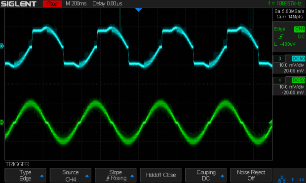
Note that “rising” means the current increases with either polarity from 0 A at the midline. The DRV8825 uses a MOSFET H-bridge to drive winding current in either direction from the +24 V motor supply voltage.
Both traces show motor winding current at 1 A/div, with the XY axes creeping along at 10 mm/min (thus, 7.1 mm/min each). The upper trace is the X axis, with a stock DRV8825 module in mixed decay mode. The lower trace is the Y axis, with its DRV8825 hacked into fast decay mode.
The basic problem, about which more later, comes from the current rising too fast during each PWM cycle:
V = L di/dt
di/dt = 24 V / 3 mH = 8 kA/s
The first 1:32 microstep away from 0 calls for 5% of max current = 50 mA at a 1 A peak. The DRV8825 datasheet says the PWM typically runs at 30 kHz = 33 µs/cycle, during which the current will change by 270 mA:
267 mA = 8 kA/s × 33.3 µs
Some preliminary measurements suggest these (probably counterfeit) DRV8825 chips actually run at 16 kHz = 66 µs/cycle:
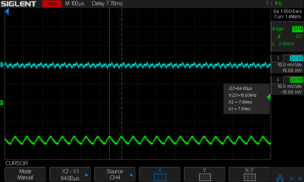
During those cycles the current can increase by more than 500 mA. The first scope picture shows an abrupt increase to maybe 700 mA, so, yeah, that’s about right.
Having the wrong current in one winding means the motor isn’t positioned correctly during those microsteps. The 3018-Pro runs at (an absurd) 1600 µstep/mm, so being off by even a full step isn’t big deal in terms of positioning.
The real problem comes from running nearly 1 A through both windings. Those little motors run really hot: they’re dissipating twice what they should be.
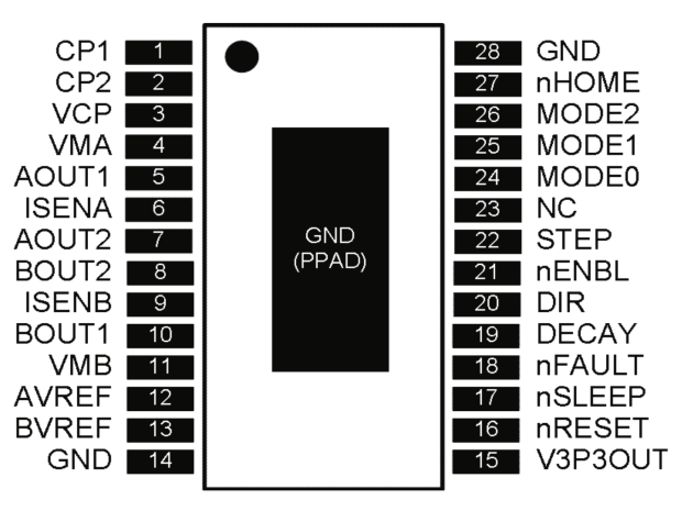
Anyhow, the pin layout shows the DRV8825 DECAY mode selection on pin 19:
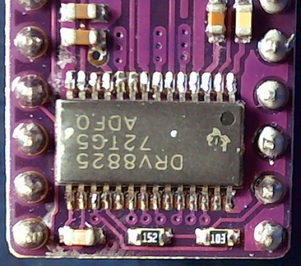
Which sits on an inconveniently skinny little PCB pad, fifth from the left on the bottom:
Memo to Self: Don’t make that mistake when you lay out a PCB. Always put a little pad or via on a disconnected pin, so as to have a hand-soldering target big enough to work with.
The objective is to pull the pin high:

Pin 15, in the lower left corner, provides the output of a 3.3 V linear regulator, with its PCB trace connected to the left side of the ceramic cap:
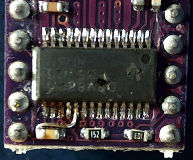
On the scale of TSSOP packages, even 30 AWG Wire-Wrap wire looks like a bus bar!
Those are two different PCBs. The crappy TI logos, not easily visible in those low-res pix, on both ICs suggest they’re by-now-typical counterfeits, so seeing a factor-of-two difference in PWM frequency isn’t surprising.

Comments
2 responses to “DRV8825 Stepper Driver: Forcing Fast Decay Mode in a (Likely) Counterfeit Chip”
[…] X axis driver is an unmodified DRV8825 PCB operating in default mixed-decay mode. The Y axis DRV8825 has its DECAY pin pulled high, thereby putting it in fast decay […]
[…] the CNC 3018-Pro steppers from 12 V would let the DRV8825 chips provide better current control in Fast Decay mode at reasonable speeds, I wondered what effect a 24 V supply would have at absurdly high speeds with […]