Adding a lock screw to the camera mount stabilized the camera-to-spindle offset enough to make calibration meaningful. Mark the spot directly under the camera:

Then mark the spot directly under the spindle, perhaps by poking a small cutter into the tape, measure the XY distances between the two center points, and use bCNC’s camera registration process to set the camera offset.
With those numbers in place, switching to the tool view (the green button with the end mill to the right in the ribbon bar) puts the camera at the spindle location:

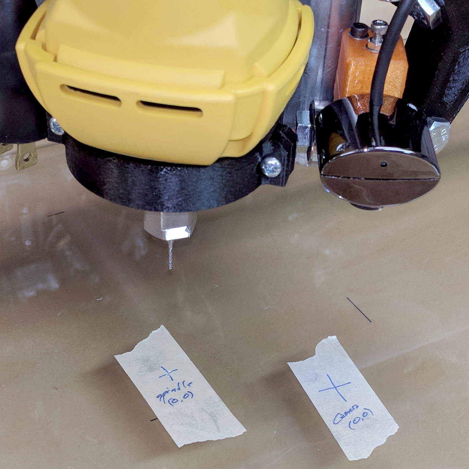
The view from outside shows the relation between those two pieces of tape:
Now I can align the camera view to a fixture position and be (reasonably) sure the spindle will automagically align to the same XY coordinate when I switch to the “tool” view. Seems to work well in preliminary tests, anyhow.

Comments
One response to “MPCNC: USB Camera Alignment”
[…] Realigning the camera and recalibrating its offset proceeded as before. […]