A closer look at the collector voltage and current for the brute-force ET227 NPN transistor motor drive:
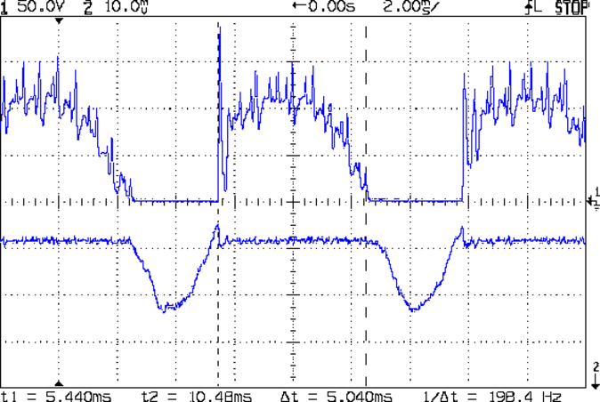
The motor current (200 mA/div) never goes to zero, but the ET227 collector voltage hits zero as the transistor saturates: the motor winding soaks up all the available line voltage and the transistor dissipation drops close to zero. The datasheet suggests VCE(sat) < 0.1 V for IC < 5 A, albeit with IB = 30 A (!).
The ET227 base drive was 77 mA, measured on a better meter than the low-resolution one in the power supply, and the transistor gain works out to 8 = 620 mA / 77 mA along those flat tops.
Eyeballometrically speaking, the dissipation averages 50 W = 90 V x 620 mA during those spiky sections where the transistor must absorb the difference between the line voltage and the motor voltage. The cursors say that takes 5 ms of the 8.3 ms period of the 120 Hz full wave rectified power, so the duty cycle is 42% and the average average dissipation works out to 20 W. That’s still enough to warm up that big heatsink; the motor driver will need a thermal sensor and a quiet fan.
That commutation noise looks pretty scary, doesn’t it?
The test setup:
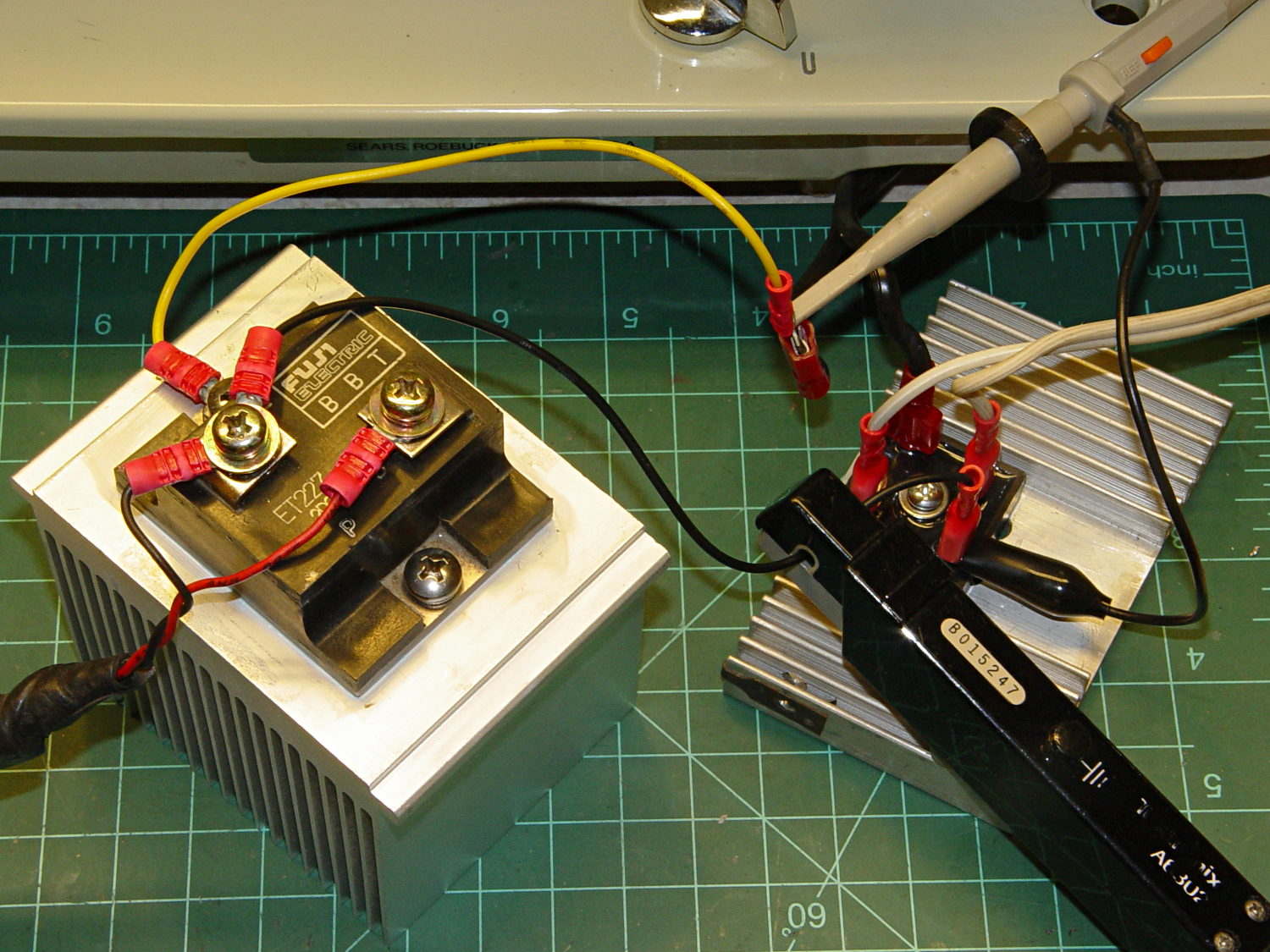
The bridge rectifier doesn’t really need a heatsink, but it looked better for a Circuit Cellar picture…

Comments
6 responses to “Kenmore 158: ET227 Transistor Drive Gain”
This used to be the one remaining place to use a germanium transistor (to get the low saturation) , but, the field is sparser than ever and may soon just be a memory.
There’s a drawer labeled “Ge xistors”, but they sure don’t have ratings like that monster! Did anybody make anything larger than small-signal germanium transistors?
There are some pretty good-sized TO-36 PNP germanium power transistors used for the 400volt inverter inside the 1970s-vintage Delta Mark 10B capacitive-discharge ignition systems. Perhaps 2N1523s or similar.
The Delta units later changed to TO-3 packaged germaniums. I have one of those units in one of the older cars around here — still works pretty well, though it did need an SCR transplant last year.
Doorknobs!
I know I’ve seen some of those in a drawer, too … hey, maybe they’re valuable antiques. [sigh]
I worked for a power supply company called Circuit Power and one of our big sellers was a 200 Amp 8.0 Volt output . early DTL, TTL , rack equipment. We used six transistors in parallel and crimped in different lengths of copper wire “resistors” to force equal current sharing.
Tune for best picture!
Back when I was the Newkid, one of the 3081 mainframe power supplies was something like -1.5 V at 1 kA. I never quite knew how they distributed that much juice among the circuitry without losing all the voltage, but it actually worked.