While setting up to drill holes in the aluminum base for the running light buck converter, I wondered if laser-marking the spots directly from the solid model would work better than my usual fumbling around.
The solid model:
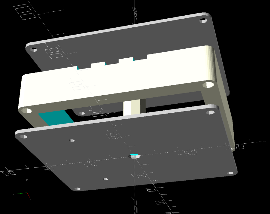
Export projections of the pieces from OpenSCAD as an SVG file:

Import into LightBurn, set up for a very fast, very light cut and Fire The Laser:

That’s in ordinary masking tape on a hard-anodized sheet of aluminum from the pile, which looked better than I expected.
The same aluminum covered with blue tape:
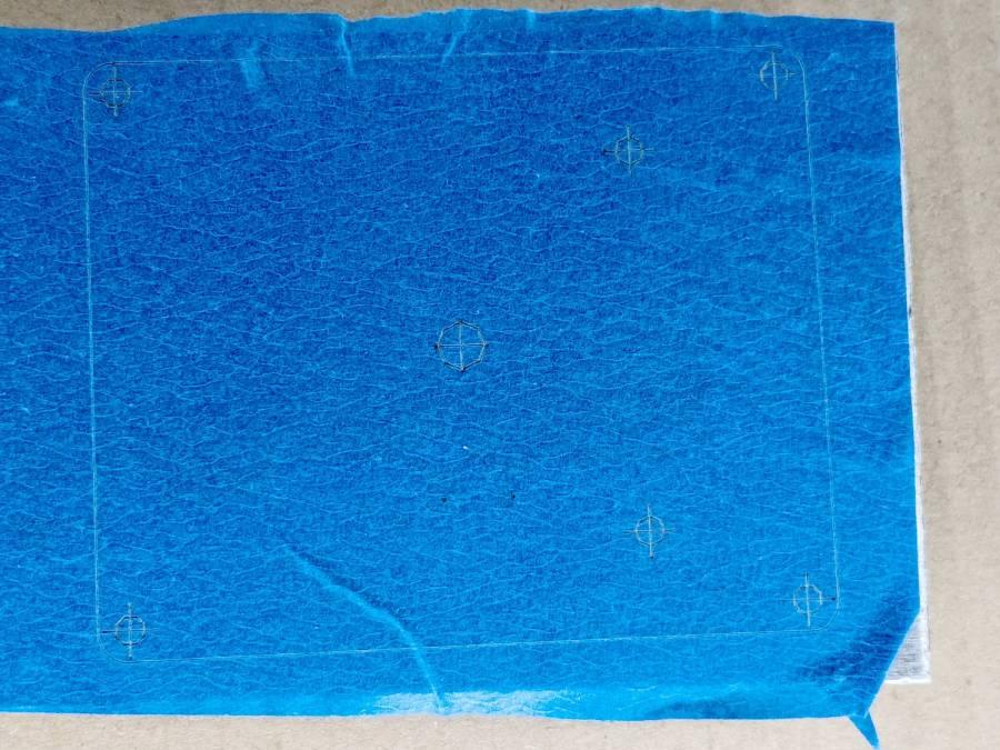
Which looks much better in person than it does in the photo.
On a soft aluminum sheet from the Basement Warehouse Zone:

The dark outline is a comfort mark hand-drawn around a chipboard test piece to verify the layout fit between random holes drilled in the sheet during its previous life.
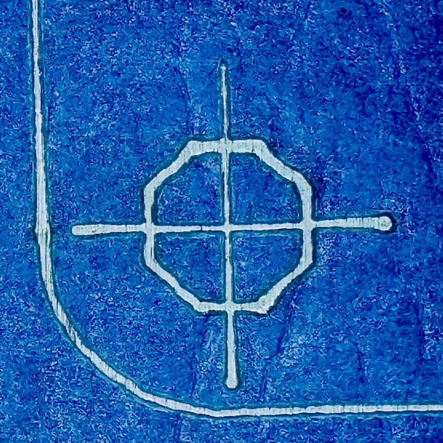
A closer look at a corner hole:
And the center hole:
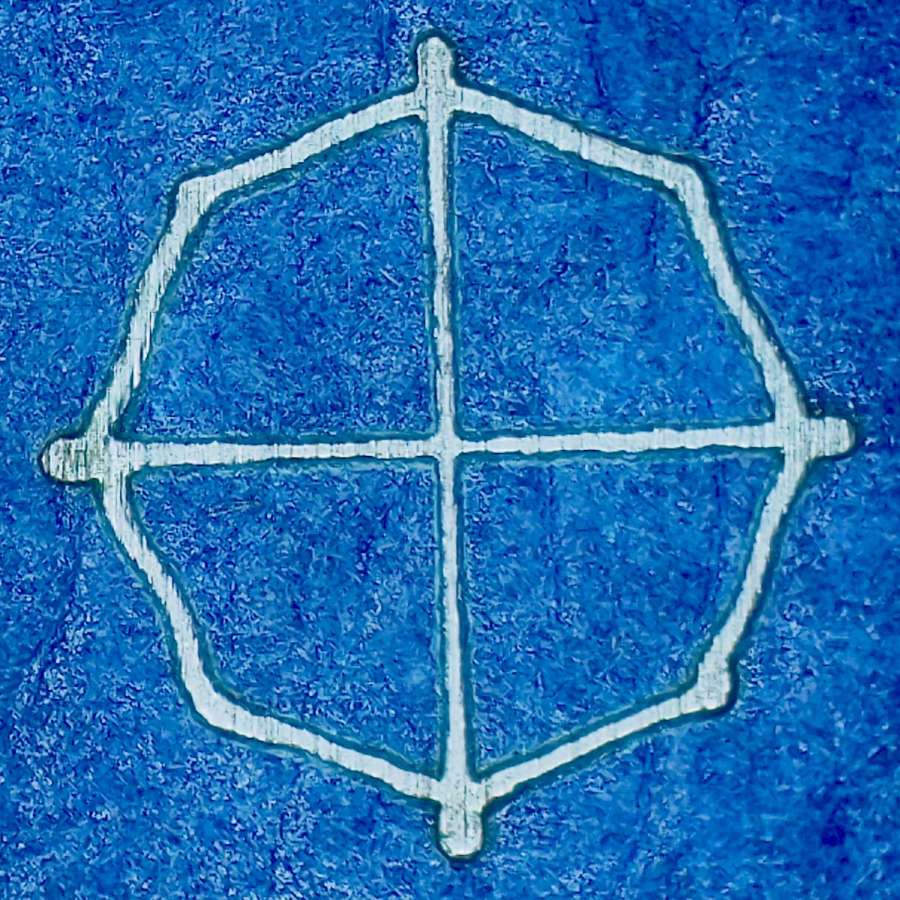
The holes appeared in the right places after center-punching by eye, but the fragility of those four little tape leaves around the center point must be experienced to be believed.
And, yes, those are deliberately low-polygon approximations to a circle, because I’m a low-poly kind of guy.
I really need an optical center punch if I do more such silliness. The box with those HP plotter digitizing sights recently came to hand, so I suppose I should make something.

Comments
6 responses to “Laser-marked Hole Drilling Spots”
Could you have the laser burn harder in the center spot in order to not have to center-punch? Maybe even burn a hole all the way through as a pilot hole?
Not on aluminum with a low-budget CO₂ laser. Metal-cutting CO₂ lasers run upwards of several hundred watts with high-pressure assist oxygen through the nozzle and specialized control firmware.
Thus far, I have fought the urge for a fiber laser to a standstill …
The new 40W diode lasers are strong enough to at least put a divot in the metal. Maybe one of those modules instead of a fiber laser.
I’ve had a vague notion to stick a diode laser module on the OMTech’s laser head carriage, but it’d smash into the rails unless I remove the CO₂ head or reduce the max travel distances by the size of the module.
Or, I suppose, fit an entire diode laser on the OMTech’s platform where it could use the exhaust airflow.
Not for a while, though … :grin:
How do you export a project as an SVG? I had a project a while back where I had to digest the 3D geometry mathematically to get a projection, it would be cool if there’s a less manual way to do it!
The projection() function apparently a recent thing:
https://en.m.wikibooks.org/wiki/OpenSCAD_User_Manual/3D_to_2D_Projection
After rendering the geometry, then there’s an SVG export for 2D objects:
https://en.m.wikibooks.org/wiki/OpenSCAD_User_Manual/Export
AFAICT there’s no automated way to render-and-export, so I included the projection() setup as one of the views, then manually render & export the result.
The crosshairs are a pair of lines in LightBurn, grouped together, snapped to the middle of a hole, and duplicated as needed. That dance is definitely a kludge, but adding them with OpenSCAD code seems even more awful.