Met this gadget outside a mall while my ladies were shopping for fabric. It’s certainly a distant relative of the snail I met near Adriance Library in Poughkeepsie some years ago with the same, then-new, camera.
It’s about a foot off the pavement on a brick wall. I fear it’s stuck, because the daytime temperatures are in the 50s and that’s pretty chilly for a cold-blooded critter.
But, on the whole, they’ve been around a lot longer than we have, so I left well enough alone.
The 6 mm stainless steel shaft I installed in late June, for reasons described there, has been working just fine.
Although the shaft has some discoloration, the idler bearing slides freely this way and that. No complaints about noises or bad shifting.
I spritzed some silicone lube on the shaft and it’s way slippery again. That’s better than petroleum lubes that tend to turn road dust into grinding compound.
The general idea is a simple light sensor that can cope with typical indoor illumination, brightening and dimming the digits on a clock so that it’s both visible in the daylight and doesn’t light up the room at night.
This circuit produces a voltage that varies more-or-less inversely with the photoresistance R. The “decade resistor” DR acts as a range selector: the output voltage will be 2.5 V when DR = R.
Yesterday I doodled about the voltage-vs-resistance curves and how DR works, showing the equations that spit out V when you know R, which is handy from a circuit-analysis standpoint (if you can say that with a straight face for a two-resistor circuit).
What you want is the equation that spits out R when you know V, because you can actually measure V. Rearranging the equation in the doodle above produces that equation
R = DR * (5 – V) / V
Actually, what you really want is log R, because your sensation of brightness varies logarithmically with the illumination intensity: each doubling of intensity makes the scenery twice as bright. So you could find R, apply a floating-point math package to it, and come up with log R.
There’s a better way.
CdS Resistance vs Voltage
Stand yesterday’s graph on its ear and flip it side-to-side to get this view of the same data points. It’s plotted with a log scale on the Y axis, because the resistance varies over such a huge range.
The dots represent the values of R produced by the equation above with DR = 1 kΩ. Those are the actual resistance values, at least according to the circuit model.
The midsection of those dots is pretty straight, so the diagonal line second from the bottom is a straight line “curve fit” with intercepts at
(0 V, log 10000)
and
(5 V, log 100)
The y = mx + b equation fitting that line is
log R = (-2/5) * V + 4
where the (-2/5) comes from the slope of the line:
(log 10000 – log 100) / (0 – 5)
and the (+ 4) comes from the intercept at (log 10000), as set by the value of DR. In fact, the intercept is 1+ (log DR), because it’s always a factor of 10 higher than the value of DR.
Now, what’s nice about that is the equation spits out log R directly, with just some multiply-divide-add action.
Changing DR by factors of 10 produces the other lines, so (as before) switching DR gives you a low-budget, wide-dynamic-range output.
DR need not be a power of 10, of course. The dashed line near the middle is DR = 3 kΩ, which puts the more-or-less linear region between about 20 kΩ (fairly dim) and 500 Ω (rather bright). That’s a useful range in my house and it might be close enough for my friend.
The dashed line approximating those points has an intercept at 1 + log 3000 = 4.5, so the overall equation is
log R = (-2/5) * V + 4.5
The approximation gets progressively worse below, say, V = 0.5 and above V = 4.5, so the outline of the algorithm is:
V < 0.5 = pretty dark: lowest digit intensity
V between 0.5 and 4.5: puzzle over log R
V > 4.5 = lots o’ light: max digit intensity
The Arduino ADC produces a 10-bit integer: 0 through 1023. Call that Vb (“V binary”), which you can scale to V like this
V = (5/1024) * Vb
Plugging that into the equation produces
log R = (-2/5) * (5/1024) * Vb + 4.5
log R = (-2/1024) * Vb + 4.5
The useful limits on Vb for the linear approximation are
V = 0.5 -> Vb = 1024 * 0.5/5 = 102
V = 4.5 -> Vb = 1024 * 4.5/5 = 922
Checking those limits against the actual formula for R
Vb = 102 -> log R = 4.3 (instead of 4.43)
Vb = 922 -> log R = 2.7 (instead of 2.52)
That’s about what you’d expect from the graph: the line is lower than the dots on the dim end (left) and higher on the bright end (right). On the other paw, getting log R without the floating-point math package makes up for that.
Now, given that you’re going to use a table lookup anyway, you don’t need any arithmetic on Vb at all. Shove all the stuff surrounding Vb to the other side of the equation
(log R – 4.5) * (-1024 / 2) = Vb
(4.5 – log R) * 512 = Vb
Precompute the left side for useful values of R, fill in the corresponding bit pattern to get the desired brightness, then index into the table with the measured Vb: shazam, log R -> brightness bits in one step!
If you’re exceedingly lucky, the brightness bits will be more-or-less in a binary sequence, in which case you can just right-shift Vb to get that number of bits and send ’em directly to the LED drivers. No table needed: one shift and you’re done!
So, for example, suppose you want eight brightness levels controlled by three Brightness Bits BB
BB = Vb >> 7
What’s not to like?
Maybe you already knew that and were wondering why it took me so long to get there…
A friend wants a digital clock that’s dim when the house lights are low; standard clocks aren’t nearly dim enough. I know how she feels, having added a primary-red filter in front of a blue vacuum-fluorescent clock display to get rid of those garish digits in the middle of the night.
This job calls for a photosensor of some kind, as you can’t figure it out by time alone.
After a brief struggle, the parts heap disgorged a 1-inch diameter CdS (cadmium sulfide) photoresistor with a dark resistance over 500 kΩ and a full-sunlight resistance around 50 Ω. Ordinary room light, at least around here, is in the 1-10 kΩ range, more or less, kinda sorta. Down the Basement Laboratory, it’s tens of kΩ.
Photoresistor circuit and equation
The canonical sensing circuit is a simple voltage divider, with the photoresistor either on the top or the bottom. Putting it on the top means the voltage increases as the light gets brighter, which has a lot to recommend it.
The resistance varies more or less linearly with the light intensity, to the extent that you can make a very nice linearly variable isolated resistor by bottling up an LED (which has linear intensity with current) with a CdS photoresistor in a light-tight enclosure.
Anyhow, although the resistance R varies linearly, having the R in the denominator means that the voltage V varies inversely. Worse, because the value of R spans about four decades, there’s a serious range & resolution problem.
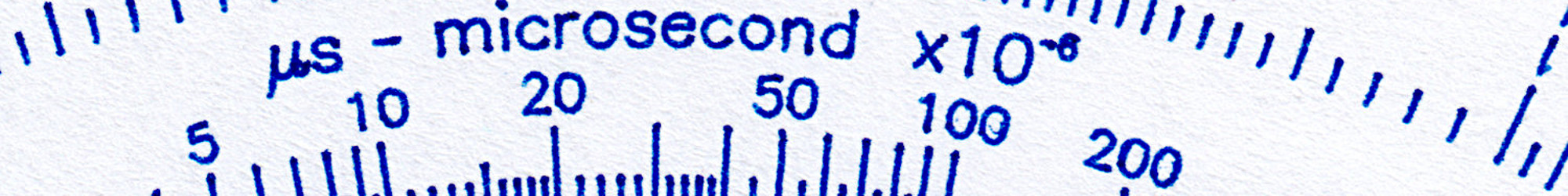
This graph of V against log R shows the situation.
Output voltage vs log resistance
The dots between R=10 Ω and R=1 kΩ are what the circuit spits out, with the “decade resistor” DR = 100 Ω and R values chosen for nice dot spacing. The long tail beyond 1 kΩ shows that for R greater than 1 kΩ, V doesn’t change by very much at all. Ditto for R less than 20 Ω or so, which is beyond the limit for this photocell.
The straight line through those points is an eyeballometric curve fit to the range from about 20 to 700 and (most crucially) passing through (10 Ω,5 V) and (1000 Ω,0 V). The equation for that line is the usual y = mx + b, albeit with (log R) where you’d expect x. The equation in the lower-left corner is pretty close to what you want, with D = log DR
V = (5/2) * ((1+D) – log R)
Running the photosensor circuit with DR = 1 kΩ would produce an identical series of dots snuggled up along the second line as R varies from 100 Ω to 10 kΩ. Each factor-of-10 change in DR handles another chunk of R’s range, with identical output voltages: when the voltage gets above about 4.5 or below 0.5, just switch to the next value of DR and continue merrily along.
So that’s a low-budget (if you have cheap relays, like MOSFET analog switches), high-dynamic-range (if you have a good buffer amplifier) light sensor.
More on how to turn this into a brightness control tomorrow…
Memo to Self: Can we correlate a digital camera’s exposure at a known ISO with the cell resistance, so I can get some remote light level values?
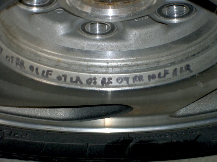
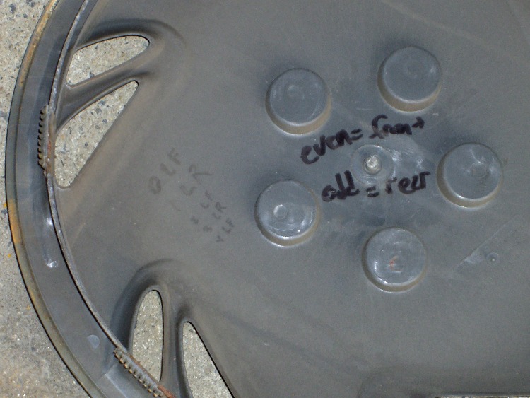
A discussion there reminded me to mention a good habit taught by my buddy Eks: when you must look something up, write the information where you’ll see it the next time you need it.
So, for example, each of the van wheels sports its own tire-rotation schedule inside the cover. When it’s time to swap tires in early spring and late autumn, I pry the cover off, read where the tire should go, and do the deed. I write ’em down four or five years at a time, so there’s not much thinking involved.
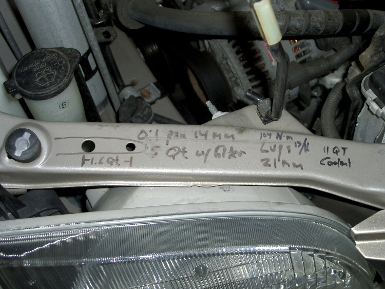
The engine compartment has all the most-often-used wrench sizes and capacities.
I write the oil change & inspection info in the maintenance schedule booklet that came with the van, although after a decade that’s pretty much full up.
Our daughter snagged some tchotchkes from a high-school career fair, including one that she instantly recognized as a flamethrower: Antibacterial Hand Sanitizer Spray, 62% Ethyl Alcohol plus some other junk, in a handy pump-spray container. Heck, it even says
Warnings Flammable. Keep away from open flame. Keep out of reach of children.
I was so proud of her…
Flare3.gif
After homework, she stuck a candle atop the garbage can by the garage and fired off a few shots while I ran the camera. Here’s the best one, converted to a low-speed animated GIF.
We’re pretty sure that’s Sweet Babby Jeebus™ in the next-to-last frame of the flare. Maybe Madonna. Could go either way.
Much as with the “movies” I made for trebuchets and tree frogs, I used ffmpeg to shred the camera’s mpg movie into separate jpg images, some bash to select the frames, then convert to stitch them back together into a gif.
The general outline:
mkdir Frames
ffmpeg -i mov04990.mpg -f image2 Frames/frame-%03d.jpg
cd Frames
mkdir flare3
for f in `seq 760 780` ; do cp frame-${f}.jpg flare3 ; done
cd flare3
convert -delay 50 frame-* Flare3.gif
If my bash-fu was stronger, I could feed the proper file names directly into convert without the copy step.
Now, kids, don’t try this at home. At least not without responsible adult supervision…
Problem: I needed a shielding plane under a sensitive gizmo that was separated from the ground plane covering the rest of the board. EAGLE poured the ground plane atop the smaller shield polygon, despite the two signals having different names.
Solution: set the ground plane’s Rank to 2, which means it’s less “important” than the smaller plane. Thus, the smaller plane gets drawn first and the ground plane surrounds it.