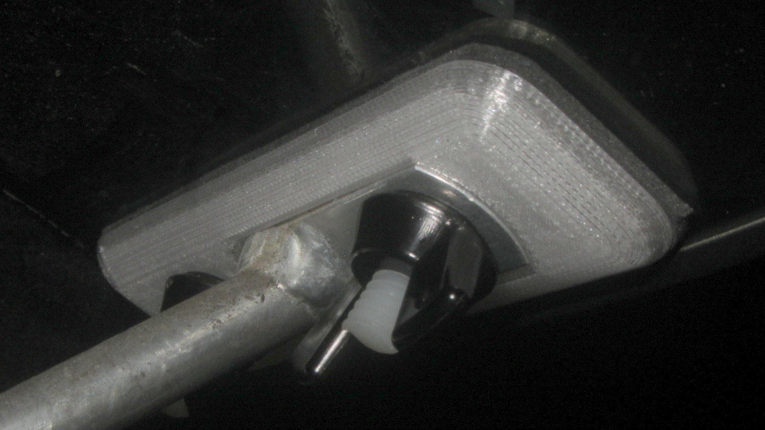
A flashlight used as a daytime running light must point generally forward and an actual bike headlight must light up the road, so it must sit on an az-el mount. My old bike helmet mirror mount had actual vertical and horizontal joints:

Every doodle along those lines seemed too big, too fragile, too fiddly, or all at once.
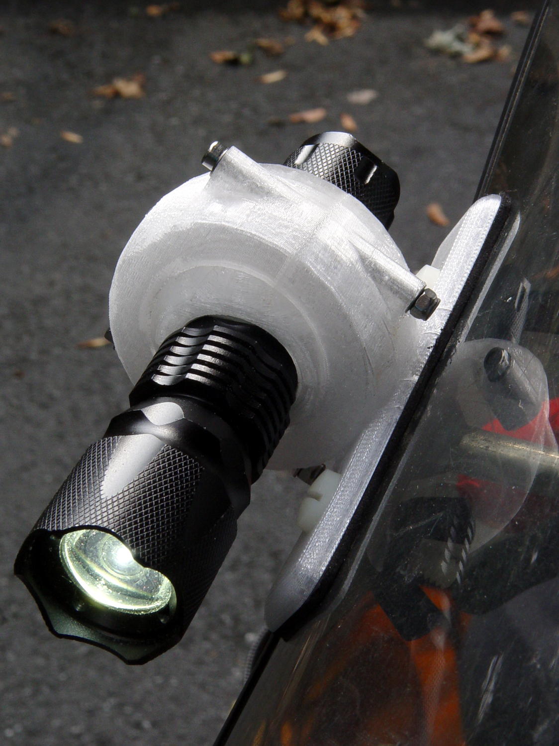
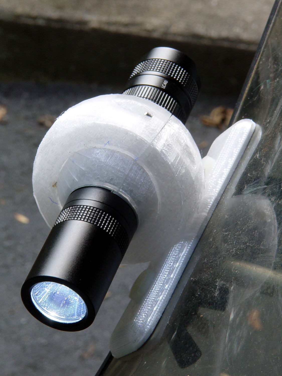
Living here in the future, though, we can produce (crude) ball joints to order:
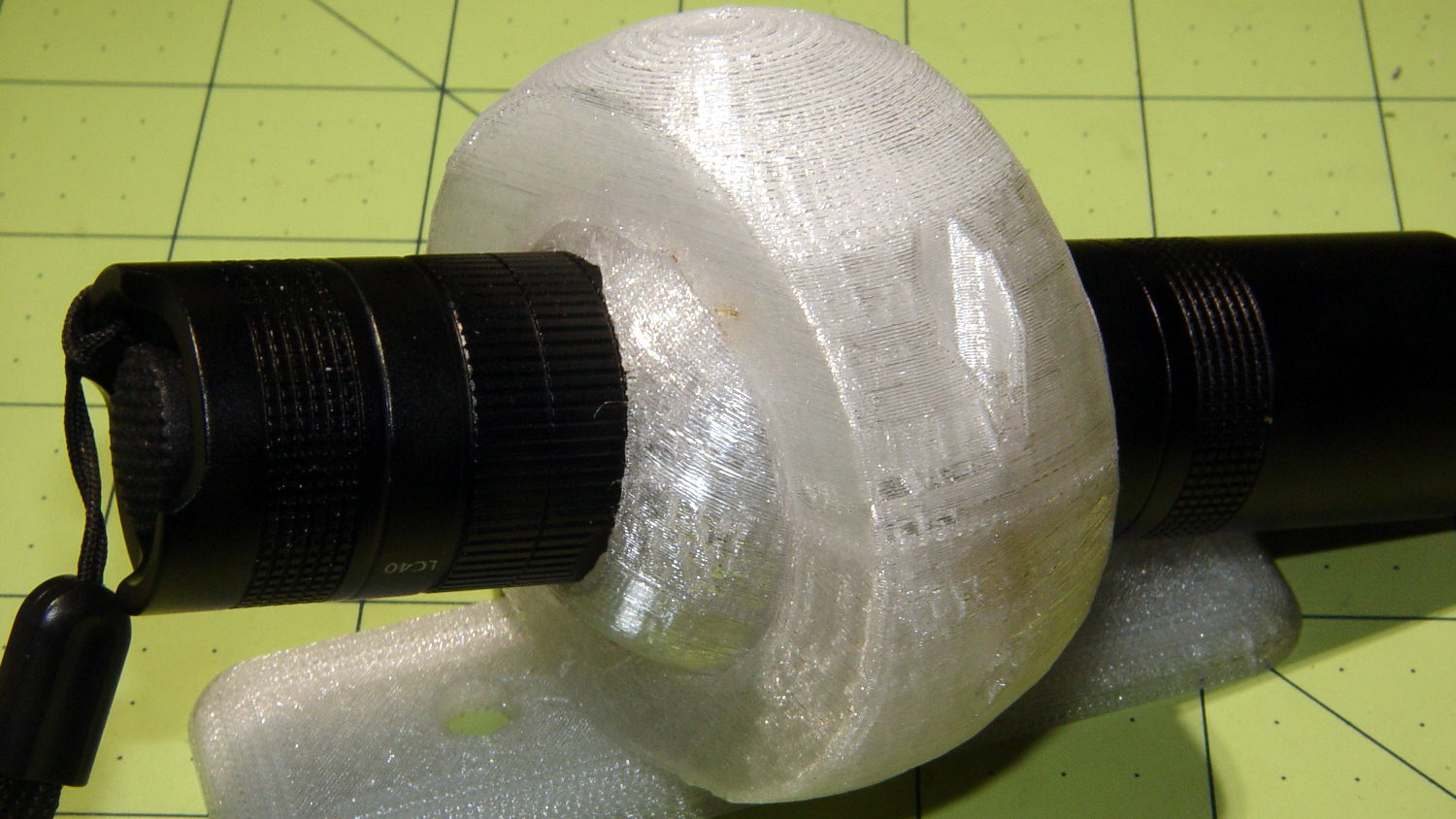
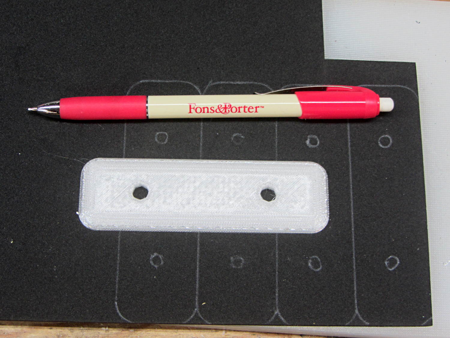
That’s an early version of the outer mount using threaded brass inserts.
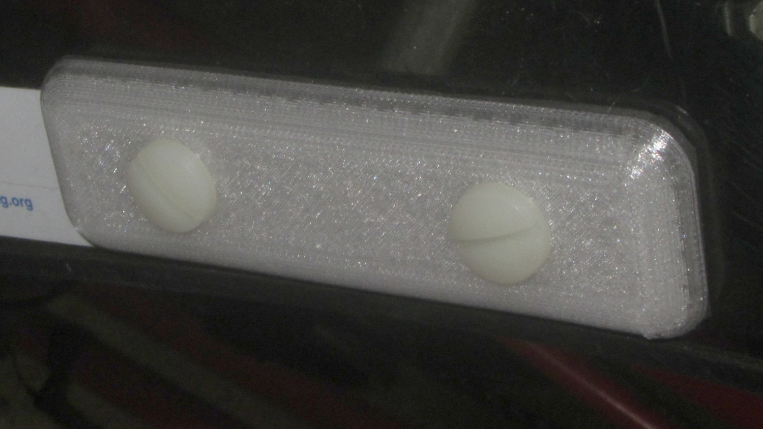
The ball around the flashlight separates along the obvious plane of symmetry, with a 2 mm socket-head cap screw and brass insert on each side. I tried printing the hemispheres convex-side-up with hand-hewn support structures inside:
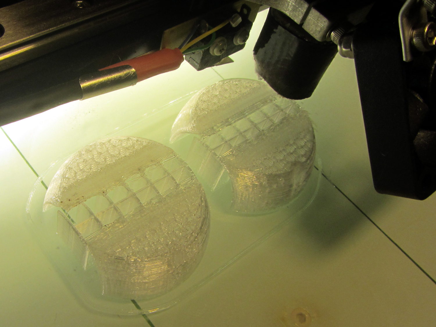
The huge overhanging sections parallel to the axis didn’t bond to the supports, curled upward, and began nudging the dangling Z-axis homing switch actuator. This wasn’t a completely wasted effort, though, as similar support structures came in handy for the outer clamp ring.
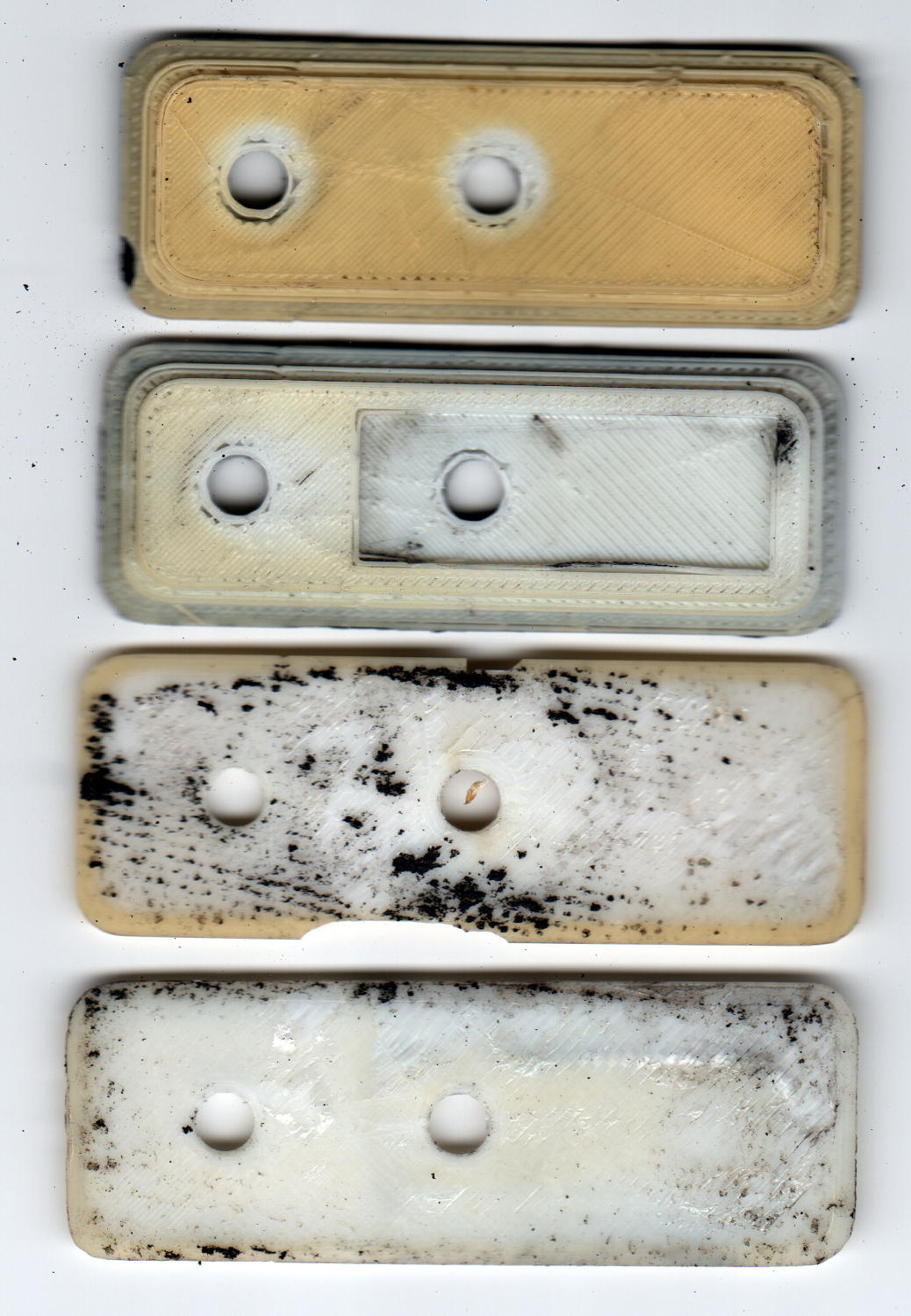
Flipping the hemispheres over so they printed U-channel upward didn’t work much better, even sitting on a flat section to eliminate the absurd part of the overhang. This view shows one hemisphere with the missing cap:
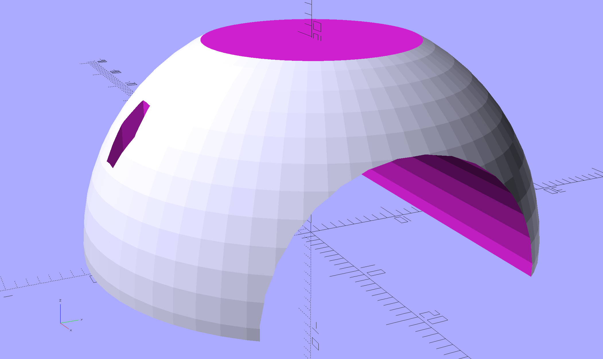
Flipped over, the flat surface bonded perfectly to the platform, but the overhang still warped as the upper layers cooled and pulled the perimeter upward:

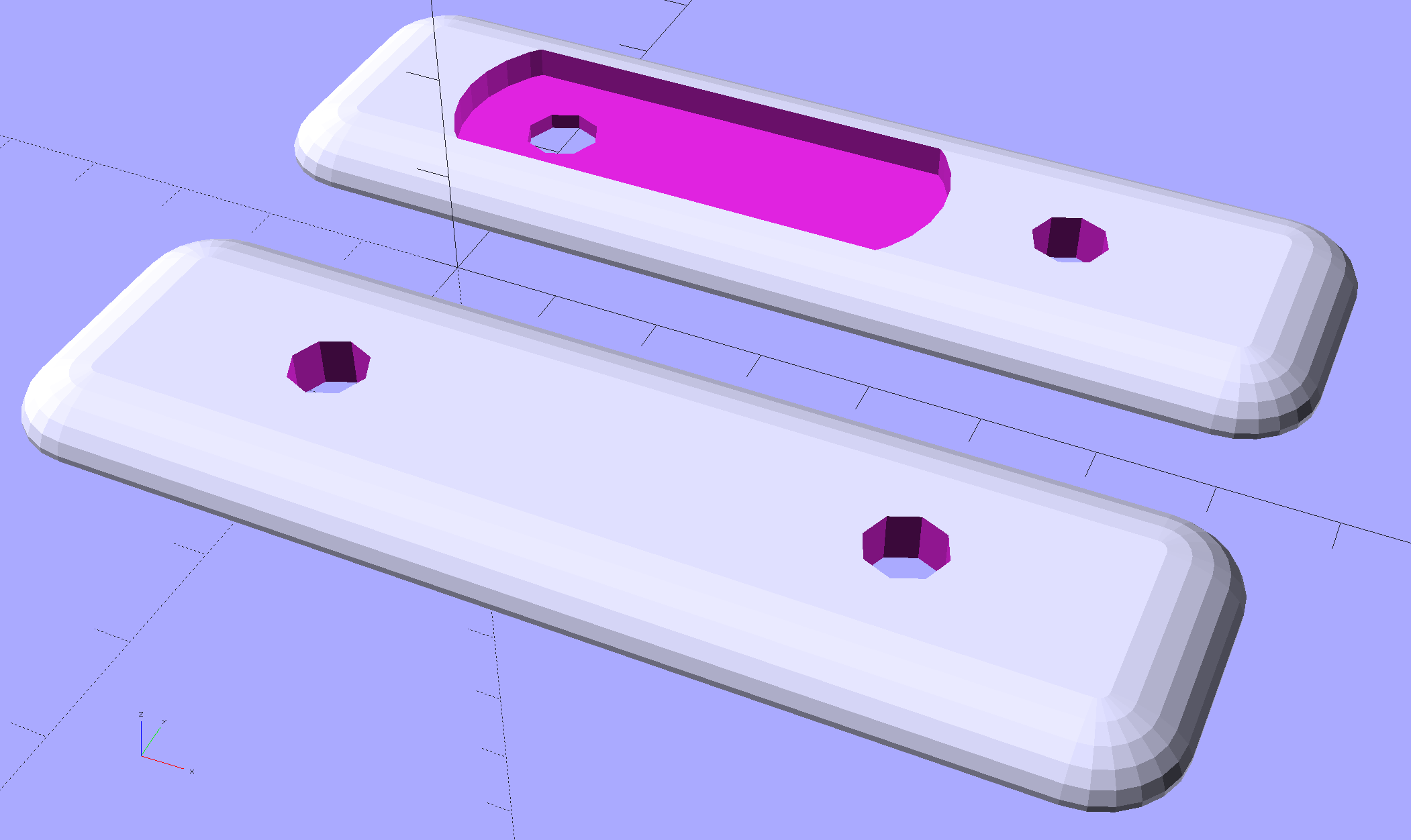
Because normal support structures don’t contact the outer surface, I added fins to the model to hold the perimeter (almost) flat until the outer walls became sufficiently vertical to stop warping:
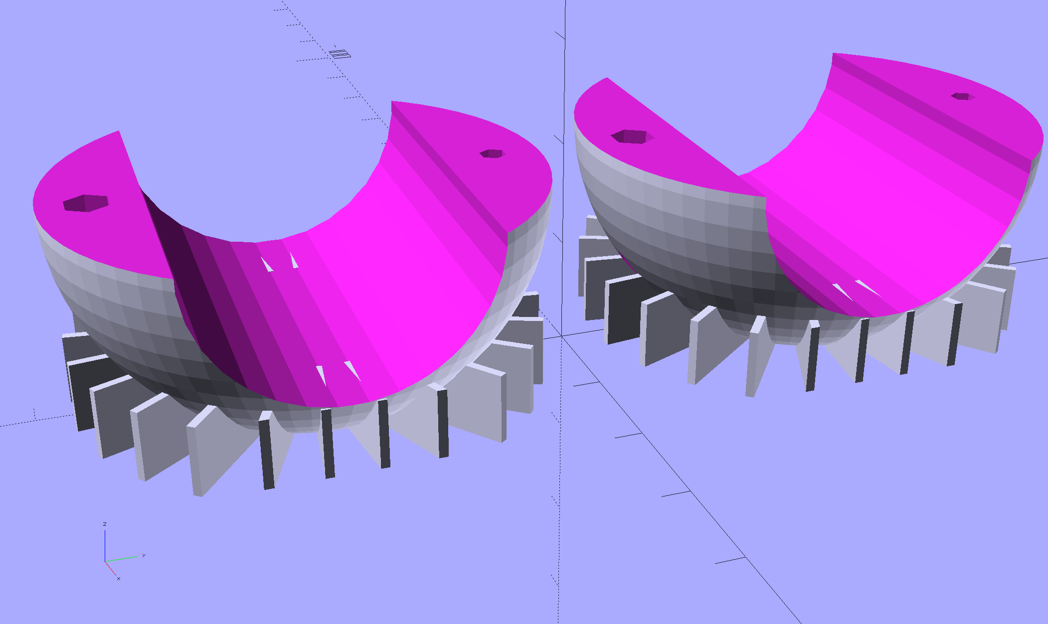
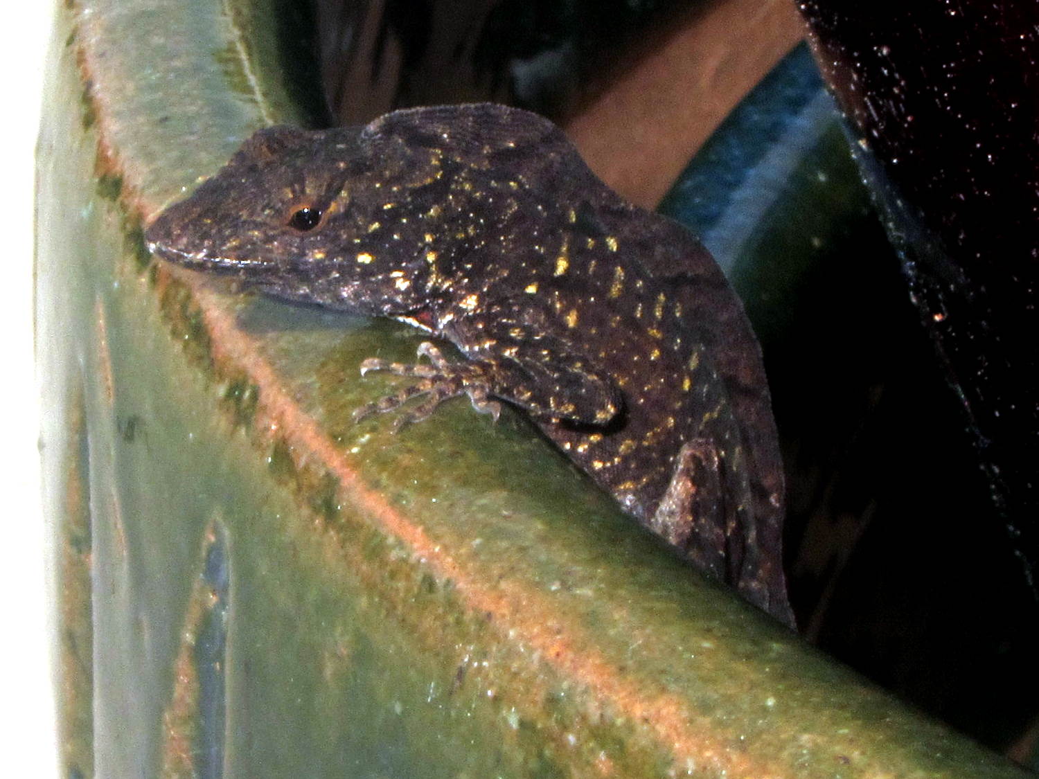
They’re fearsome hedgehogs in person:
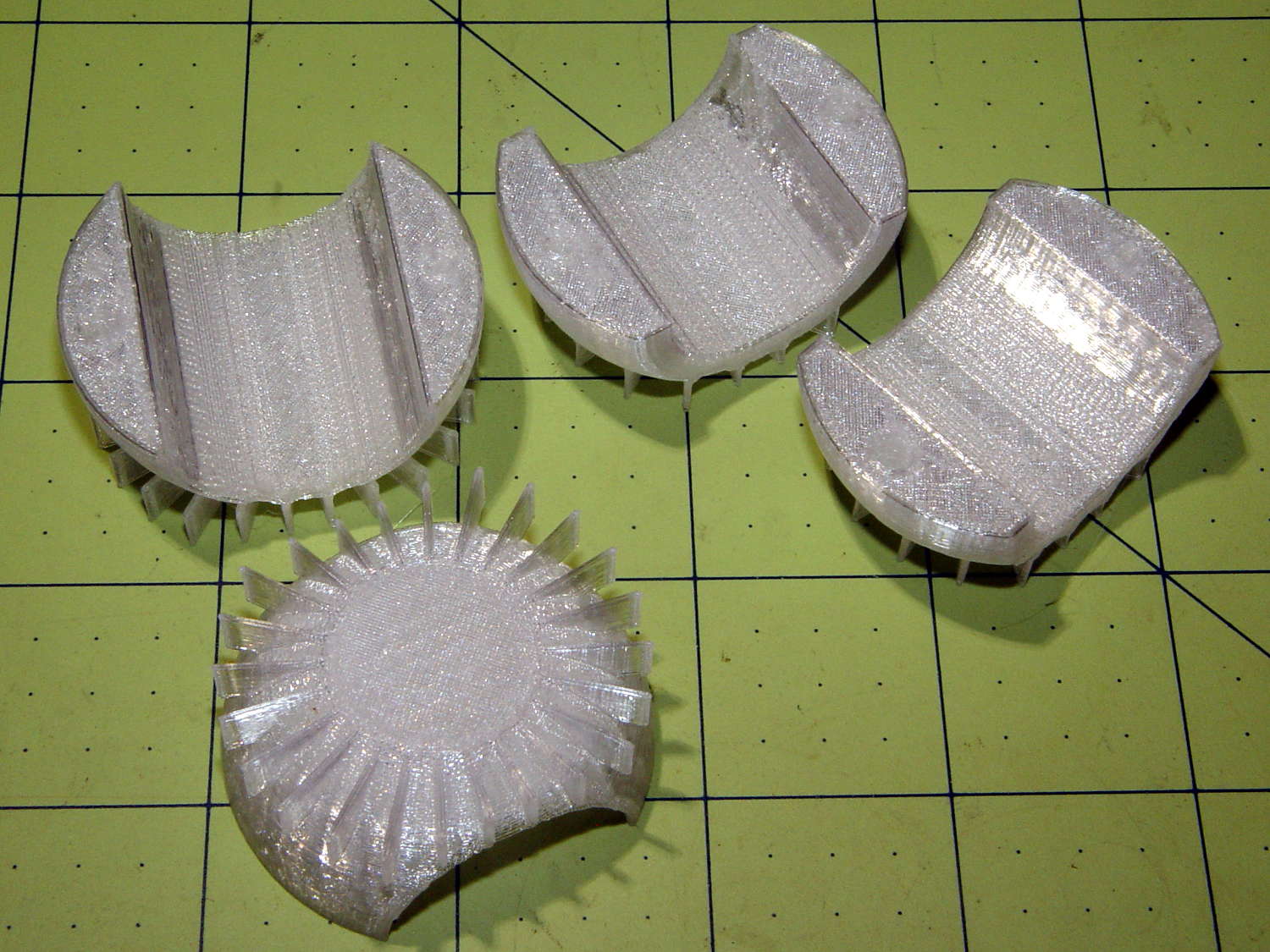
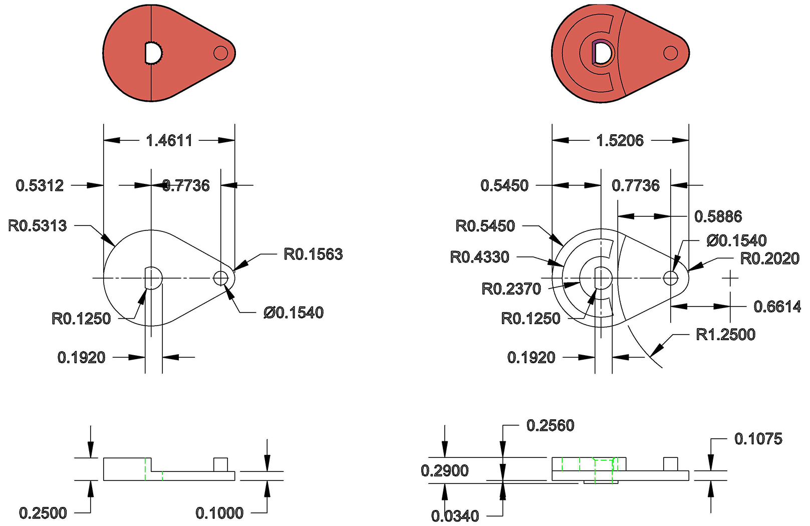
The grip diameter determines the sphere diameter, as the sphere must have enough meat next to the grip to hold the screws and inserts. Rather than have the diameter different for every flashlight, I set it to the maximum of 45 mm or the actual diameter, which means all the flashlights in my collection have a common ball size. The hemispheres on the right have flattened ends to accommodate flashlight grips shorter than the sphere’s final diameter, achieved with a pair of intersection() operations lopping off the protruding bits:
| //- Ball around flashlight | |
| // Must print two! | |
| module BodyBall() { | |
| difference() { | |
| intersection() { | |
| sphere(d=BallOD,$fn=2*NumSides); // basic ball | |
| cube([BallLength,2*BallOD,2*BallOD],center=true); // max of flashlight grip length | |
| } | |
| translate([-LightBodies[FlashIndex][F_GRIPOD],0,0]) | |
| rotate([0,90,0]) rotate(180/NumSides) | |
| PolyCyl(LightBodies[FlashIndex][F_GRIPOD],2*BallOD,NumSides); // flashlight body | |
| for (j=[-1,1]) | |
| translate([0,j*BallScrewOC/2,0]) // commmon screw offset | |
| translate([0,0,-BallOD]) | |
| PolyCyl(BallInsert[ID],2*BallOD,6); // punch screw shaft through everything | |
| translate([0,BallScrewOC/2,-Protrusion]) | |
| PolyCyl(BallInsert[OD],(BallInsert[LENGTH] + 3*ThreadThick + Protrusion),6); // threaded insert | |
| translate([0,-BallScrewOC/2,BallThick]) | |
| PolyCyl(BallScrew[OD],BallOD,6); // screw head clearance | |
| translate([0,0,-BallOD/2]) // remove bottom half | |
| cube(BallOD,center=true); | |
| translate([0,0,BallOD – BallThick/2]) // slice off top = bottom for E-Z build | |
| cube(BallOD,center=true); | |
| } | |
| if (Support) { | |
| NumRibs = 24; | |
| RibHeight = (BallOD – LightBodies[FlashIndex][F_GRIPOD]/cos(180/NumSides) – BallThick) / 2; | |
| ChordC = 2*sqrt(BallThick*BallOD/2 – pow(BallThick/2,2)); | |
| intersection() { | |
| cube([BallLength,2*BallOD,2*BallOD],center=true); // max of flashlight grip length | |
| translate([0,0,BallOD/2 – BallThick/2]) | |
| for (i=[0:NumRibs – 1]) | |
| rotate(i*360/NumRibs + 180/NumRibs) // avoid screw holes | |
| translate([ChordC/2 + BallOD/8,0,-RibHeight/2]) | |
| cube([BallOD/4,2*ThreadWidth,RibHeight],center=true); | |
| } | |
| } | |
| } |
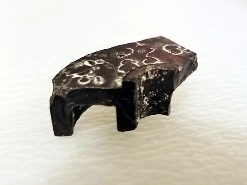
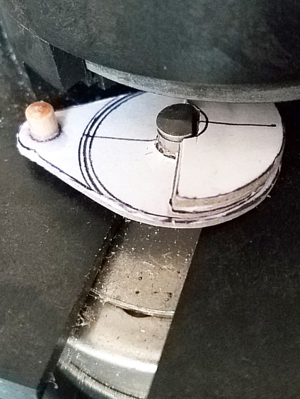
Because the fins extend from resolutely convex surfaces, I snipped them off with flush-cutting pliers, reamed out the holes, epoxied the inserts in place, assembled the ball, and introduced it to Mr Belt Sander.
Protip: don’t hold the ball with your finger through the hole. It will eventually fly off under the workbench and it’s better if it doesn’t break your finger in the process.
A somewhat rough outer surface turns out to be an advantage, not a liability, as the clamp ring around the ball must hold it against the normal (and unusually severe) vibrations found on a bike.
The inner cylindrical section is smooth enough to require a wrap of tape around the flashlight grip to anchor it in position. The tape adheres to the flashlight and squishes into the ball’s layer lines, even under mild pressure from the 2 mm screws. The outer clamp ring applies compression to the ball, so the tiny screws need not withstand much force at all, which is a good thing.